manuals.online logo
Brands
  1. Home
  2. •
  3. Brands
  4. •
  5. hepco & becker
  6. •
  7. Motorcycle Accessories
  8. •
  9. hepco & becker 5012538 00 01 User manual

hepco & becker 5012538 00 01 User manual

1
Motorschutzbügel/ Engine guard
KAWASAKI Z400
ab Baujahr 2019 / from date of manufacture 2019
Artikel Nr.: / Item-no.:
5012538 00 01 schwarz/black
170619
INHALT
CONTENT
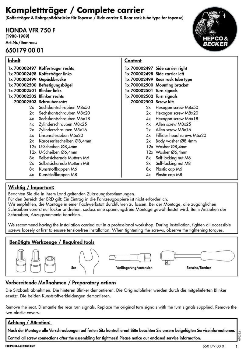
BENÖTIGTE WERKZEUGE
TOOLS REQUIRED
1x 700010430 Motorschutzbügel links
1x 700010431 Motorschutzbügel rechts
1x 700010432 Schraubensatz:
1x 700010430 Engine guard left
1x 700010431 Engine guard right
1x 700010432 Screw kit:
Zylinderschraube ISK M10x1,25x130 1x
Zylinderschraube ISK M10x1,25x90 1x
Zylinderschraube ISK M10x300 1x
U-Scheibe Ø10,5 4x
Stahldistanz schwarz Ø22xØ14x29 2x
Stahldistanz schwarz Ø22xØ14x81 1x
Stahldistanz schwarz Ø22xØ14x46 1x
Selbstsichernde Mutter M10 1x
Abdeckkappe M10 1x
Verbindungsstück Ø25 1x
Allen screw M10x1,25x130 1x
Allen screw M10x1,25x90 1x
Allen screw M10x300 1x
Washer Ø10,5 4x
Steel spacer black Ø22xØ14x29 2x
Steel spacer black Ø22xØ14x81 1x
Steel spacer black Ø22xØ14x46 1x
Self lock nut M10 1x
Plastic cap M10 1x
Connector Ø25 1x
Set Verlängerung/extension Ratsche/Ratchet
2
5012538 00 01
WICHTIG
IMPORTANT
Beachten Sie die in Ihrem Land geltenden Zulassungsbestimmungen.
Für den Bereich der BRD gilt: Ein Eintrag in die Fahrzeugpapiere ist nicht erforderlich.
Die Voraussetzung für die Montage ist natürlich eine gewisse technische Erfahrung. Wenn Sie sich nicht sicher sind,wie
man eine bestimmte Arbeit ausführt, sollten Sie diese Ihrer Fachwerkstatt überlassen.
Ziehen sie alle zugänglichen Schrauben zuerst nur locker an. Nachdem alles montiert ist, werden die Schrauben dann auf
das entsprechende Anzugsmoment festgezogen. Dadurch wird sichergestellt, dass das Produkt spannungsfrei angebaut ist.
Anzugsmomente beachten! Nach der Montage alle Verschraubungen auf festen Sitz kontrollieren!
Of course, the assembly requires a certain technical experience. If you are not sure how to execute a determined action,
you should ask your local distributor to do it. First, tighten all screws only loosely. After mounting all parts, the screws
should be tightened to the torque specified. This guarantees, that the product is mounted without tension. Observe
the tightening torques of the manufacturer! Control all screw connections after the assembling for tightness!
VORBEREITUNG
PREPARING
Die Verkleidung auf der linken Seite entfernen, hierfür die 3 Schrauben lösen. Die Schraube der vorderen
sowie die Durchgangsschraube der hinteren Rahmenbefestigung entfernen, alle Schrauben entfallen. Vorsicht,
beim Entfernen der vorderen Schraube kann die Distanzscheibe herunterfallen. Diese wird wiederverwendet!
Remove the left side fairing by loosening the 3 screws. Remove the screw of the front and the long continuous
screw of the rear frame fixing, all screws are omitted. Be careful, when removing the front screw - the spacer
may fall down. It will be reused!
ACHTUNG
CAUTION
Immer nur eine Seite nach der anderen montieren. Ansonsten besteht die Gefahr, dass sich der Motor absenkt.
Mit der linken Seite beginnen.
Mount one side after the other. Otherwise, there is the risk that the engine block change position.
Start with the left side.
MONTAGEANLEITUNG
MOUNTING INSTRUCTIONS
1
1x
1x
1x
Montage des Motorschutzbügel links vorne:
Mit der Zylinderschraube M10x1,25x130
sowie U-Scheibe Ø10,5.
Zuerst Stahldistanz Ø22xØ14x81in die nun
freie Gewindebohrung einfügen.
Fastening of the engine guard left front:
With the allen screw
M10x1,25x130
and
washer
Ø10,5.
First, insert steel spacer Ø22xØ14x81 into
the now free sleeve.
Fahrtrichtung/driving direction
3
5012538 00 01
2
3
1x
1x
1x
1x
1x
1x
1x
Montage des Motorschutzbügel links hinten:
Die Montage erfolgt in der nun freien Bohrung
mit der Zylinderschraube M10x300 sowie
U- Scheibe Ø10,5. Zwischen Lasche und
Rahmen die Stahldistanz Ø22xØ14x29 fügen.
Montage des Motorschutzbügel rechts vorne:
Vorab die Schraube der Rahmenbefestigung
entfernen, diese entfällt. Die Montage erfolgt
in der nun freien Gewindebohrung mit der
Zylinderschraube M10x1,25x90 sowie
U- Scheibe Ø10,5. Zwischen Lasche und
Rahmen die Stahldistanz Ø22xØ14x46 fügen.
Vorne die beiden Bügelhälften zusammen-
stecken.
Fastening of the engine guard left rear:
At the now free thread with the allen screw
M10x300
and washer
Ø10,5.
Between the lug and the frame add the steel
spacer
Ø22xØ14x29
.
Fastening of the engine guard right front:
First remove the screw of the frame faste-
ning, screw is obsolet. To fix the guard in the
now free threaded hole use the allen screw
M10x1,25x90 and washer Ø10,5. Insert the
steel spacer Ø22xØ14x46 between the lug
and the frame. Connect the two crash bars
together at the front.
Fahrtrichtung/driving direction
Verbindungsstück Ø25 in das Rohrende des Motorschutzbügels fügen.
Insert the Ø25 connector into the tube end of the crash bar.
MONTAGEANLEITUNG
MOUNTING INSTRUCTIONS
Fahrtrichtung/driving direction
4
5012538 00 01
MONTAGEANLEITUNG
MOUNTING INSTRUCTIONS
Hepco & Becker GmbH
An der Steinmauer 6
D-66955 Pirmasens
Germany
Tel.: +49 (0)6331 - 1453 - 100
Fax: +49 (0)6331 - 1453 - 120
eMail: vertrieb@hepco-becker.de
www.hepco-becker.de
Als weiteres Zubehör lieferbar:/ Also available:
Weiteres Zubehör auf unsere Homepage. More accessories: see our homepage.
5032538 00 01 Frontschutzbügel / Front guard
5062538 00 09 Tankring
6302538 00 01 C- Bow
6702538 00 01 Sportrack
42112538 00 91 Seitenständerplatte / Side stand enlargement
ACHTUNG
CAUTION
Nach der Montage alle Verschraubungen auf festen Sitz kontrollieren ! Abgebaute Teile wieder montieren.
Bitte beachten Sie unsere beigefügten Serviceinformationen.
Control all screw connections after the assembling for tightness! Reassemble the dismanteled parts.
Please notice our enclosed service information.
4
1x 1x 1x
Montage des Motorschutzbügel rechts hinten:
Die Montage erfolgt am überstehenden Ge-
winde der bereits gefügten Schraube mit der
selbstsichernden Mutter M10 sowie U-Scheibe
Ø10,5. Zwischen Lasche und Rahmen die
Stahldistanz Ø22xØ14x29 fügen.
Die Abdeckkappe M10 auf die Mutter fügen.
Fastening of the engine guard right rear:
On the protruding thread of the already
joined screw with the self-lock nut M10
and washer Ø10,5. Insert the steel spacer
Ø22xØ14x29 between the lug and the
frame. Fit the cover cap M10 onto the nut.
Fahrtrichtung/driving direction

Other hepco & becker Motorcycle Accessories manuals
hepco & becker SPORTRACK 670.4543 User manual

hepco & becker

hepco & becker SPORTRACK 670.4543 User manual

hepco & becker LEGACY 636669 00 01L User manual

hepco & becker

hepco & becker LEGACY 636669 00 01L User manual

hepco & becker Sportrack 6707545 00 01 User manual

hepco & becker

hepco & becker Sportrack 6707545 00 01 User manual

hepco & becker Sportrack 6709509 00 01 User manual

hepco & becker

hepco & becker Sportrack 6709509 00 01 User manual

hepco & becker Easyrack 661755 01 01 User manual

hepco & becker

hepco & becker Easyrack 661755 01 01 User manual

hepco & becker 6303532 00 01 User manual

hepco & becker

hepco & becker 6303532 00 01 User manual

hepco & becker KR4999-111 User manual

hepco & becker

hepco & becker KR4999-111 User manual

hepco & becker 8007581 00 01 User manual

hepco & becker

hepco & becker 8007581 00 01 User manual

hepco & becker Lock it 506017-4 User manual

hepco & becker

hepco & becker Lock it 506017-4 User manual

hepco & becker 42127531 00 01 User manual

hepco & becker

hepco & becker 42127531 00 01 User manual

hepco & becker 630724 00 01 User manual

hepco & becker

hepco & becker 630724 00 01 User manual

hepco & becker 6004519 00 02 User manual

hepco & becker

hepco & becker 6004519 00 02 User manual

hepco & becker Easyrack 6614526 01 01 User manual

hepco & becker

hepco & becker Easyrack 6614526 01 01 User manual

hepco & becker 501984 00 01 User manual

hepco & becker

hepco & becker 501984 00 01 User manual

hepco & becker 740003 User manual

hepco & becker

hepco & becker 740003 User manual

hepco & becker 42106514 00 01 User manual

hepco & becker

hepco & becker 42106514 00 01 User manual

hepco & becker 6506525 00 01 Quick start guide

hepco & becker

hepco & becker 6506525 00 01 Quick start guide

hepco & becker 630676 00 01 User manual

hepco & becker

hepco & becker 630676 00 01 User manual

hepco & becker 6613518 01 01 User manual

hepco & becker

hepco & becker 6613518 01 01 User manual

hepco & becker 630989 00 02 User manual

hepco & becker

hepco & becker 630989 00 02 User manual

hepco & becker 5039507 00 01 User manual

hepco & becker

hepco & becker 5039507 00 01 User manual

hepco & becker 8004559 00 01 User manual

hepco & becker

hepco & becker 8004559 00 01 User manual

hepco & becker Sportrack 6709524 00 01 User manual
hepco & becker

hepco & becker Sportrack 6709524 00 01 User manual

hepco & becker 6613529 01 01 User manual

hepco & becker

hepco & becker 6613529 01 01 User manual

Popular Motorcycle Accessories manuals by other brands

Mastech FREEDOM Series Assembly instructions

Mastech

Mastech FREEDOM Series Assembly instructions

DUCATI Performance 96981461AA quick start guide

DUCATI Performance

DUCATI Performance 96981461AA quick start guide

Chicago Electric 64527 owner's manual

Chicago Electric

Chicago Electric 64527 owner's manual

Saddlemen 882-09-all User's guide & installation instructions

Saddlemen

Saddlemen 882-09-all User's guide & installation instructions

SCHUBERTH SRC system 9049100303 quick start guide

SCHUBERTH

SCHUBERTH SRC system 9049100303 quick start guide

KLOCK WERKS Flare Installation instruction

KLOCK WERKS

KLOCK WERKS Flare Installation instruction

Alpinestars Tech-Air 10 System System Operation

Alpinestars

Alpinestars Tech-Air 10 System System Operation

Polaris 2869924 user manual

Polaris

Polaris 2869924 user manual

SCHUBERTH BER 80 manual

SCHUBERTH

SCHUBERTH BER 80 manual

rally rampage RNHC user manual

rally rampage

rally rampage RNHC user manual

Airoh WRAAP instructions

Airoh

Airoh WRAAP instructions

NZI Helmets Activy 3 owner's manual

NZI Helmets

NZI Helmets Activy 3 owner's manual

R&G SP0085BK Fitting instructions

R&G

R&G SP0085BK Fitting instructions

Cobra 602-2500 instruction manual

Cobra

Cobra 602-2500 instruction manual

LSL 150H131 FITTING INSTRUCTION

LSL

LSL 150H131 FITTING INSTRUCTION

J&M Corporation HCRK-7252GTM-XXR installation instructions

J&M Corporation

J&M Corporation HCRK-7252GTM-XXR installation instructions

Crivit 78791 Instructions for use

Crivit

Crivit 78791 Instructions for use

SHOEI HORNET ADV Instructions for use

SHOEI

SHOEI HORNET ADV Instructions for use

manuals.online logo
manuals.online logoBrands
  • About & Mission
  • Contact us
  • Privacy Policy
  • Terms and Conditions

Copyright 2025 Manuals.Online. All Rights Reserved.