manuals.online logo
Brands
  1. Home
  2. •
  3. Brands
  4. •
  5. hepco & becker
  6. •
  7. Motorcycle Accessories
  8. •
  9. hepco & becker SOLID 5089529 00 01 User manual

hepco & becker SOLID 5089529 00 01 User manual

This manual suits for next models

4

Other hepco & becker Motorcycle Accessories manuals
hepco & becker 810660 00 12 User manual

hepco & becker

hepco & becker 810660 00 12 User manual

hepco & becker 630732 00 01 User manual

hepco & becker

hepco & becker 630732 00 01 User manual

hepco & becker 6307507 00 02 Installation guide
hepco & becker

hepco & becker 6307507 00 02 Installation guide

hepco & becker LEGACY 6357530 00 01 User manual

hepco & becker

hepco & becker LEGACY 6357530 00 01 User manual

hepco & becker Minirack 6606513 01 01 User manual

hepco & becker

hepco & becker Minirack 6606513 01 01 User manual

hepco & becker 6304520 00 01 User manual

hepco & becker

hepco & becker 6304520 00 01 User manual

hepco & becker 5066502 00 09 User manual

hepco & becker

hepco & becker 5066502 00 09 User manual

hepco & becker 741665 00 01 User manual

hepco & becker

hepco & becker 741665 00 01 User manual

hepco & becker 5012524 00 01 User manual

hepco & becker

hepco & becker 5012524 00 01 User manual

hepco & becker 700315 User manual

hepco & becker

hepco & becker 700315 User manual

hepco & becker Easyrack 661671 01 01 User manual

hepco & becker

hepco & becker Easyrack 661671 01 01 User manual

hepco & becker 710634 00 01 User manual

hepco & becker

hepco & becker 710634 00 01 User manual

hepco & becker 5013530 00 01 User manual

hepco & becker

hepco & becker 5013530 00 01 User manual

hepco & becker 5019506 00 02 User manual

hepco & becker

hepco & becker 5019506 00 02 User manual

hepco & becker 650541 00 01 User manual

hepco & becker

hepco & becker 650541 00 01 User manual

hepco & becker Easyrack User manual

hepco & becker

hepco & becker Easyrack User manual
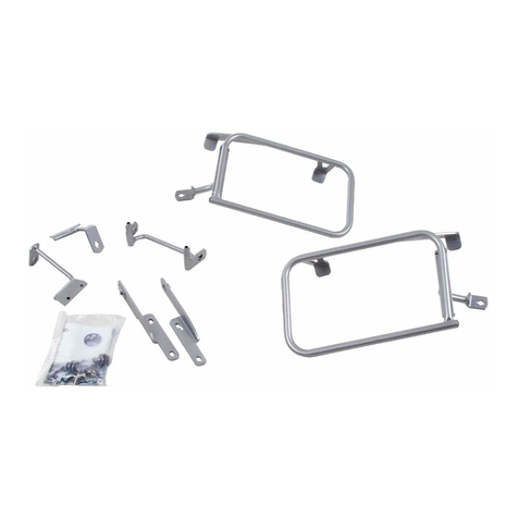
hepco & becker 650793 01 02 User manual

hepco & becker

hepco & becker 650793 01 02 User manual

hepco & becker 6307623 00 01 User manual

hepco & becker

hepco & becker 6307623 00 01 User manual

hepco & becker 5032545 00 01 User manual

hepco & becker

hepco & becker 5032545 00 01 User manual

hepco & becker 5014559 00 05 User manual

hepco & becker

hepco & becker 5014559 00 05 User manual

hepco & becker 650.961 00 01 User manual

hepco & becker

hepco & becker 650.961 00 01 User manual

hepco & becker 5027552 00 22 User manual

hepco & becker

hepco & becker 5027552 00 22 User manual

hepco & becker 6547593 00 01 User manual

hepco & becker

hepco & becker 6547593 00 01 User manual

hepco & becker Easyrack User manual

hepco & becker

hepco & becker Easyrack User manual

Popular Motorcycle Accessories manuals by other brands

SRC H-ADV150-04-01AL quick start guide

SRC

SRC H-ADV150-04-01AL quick start guide

DMD P1 owner's manual

DMD

DMD P1 owner's manual

GIVI Airflow AF1110 manual

GIVI

GIVI Airflow AF1110 manual

Suzuki 99143-00A1 000 Series installation instructions

Suzuki

Suzuki 99143-00A1 000 Series installation instructions

Cardo Systems FREECOM 4+ Pocket guide

Cardo Systems

Cardo Systems FREECOM 4+ Pocket guide

Shark S 700 user manual

Shark

Shark S 700 user manual

R&G CR0081 Fitting instructions

R&G

R&G CR0081 Fitting instructions

SRC B-TRK502-01-01-SL quick start guide

SRC

SRC B-TRK502-01-01-SL quick start guide

HOMCOM AA0-077 user manual

HOMCOM

HOMCOM AA0-077 user manual

SHOEI JO Instructions for use

SHOEI

SHOEI JO Instructions for use

Wunderkind Custom 106503-F15 Installation and safety

Wunderkind Custom

Wunderkind Custom 106503-F15 Installation and safety

Suzuki 57100-05881 installation instructions

Suzuki

Suzuki 57100-05881 installation instructions

SIKH HELMETS Y-61 quick start guide

SIKH HELMETS

SIKH HELMETS Y-61 quick start guide

Dräger HPS 3500 Instructions for use

Dräger

Dräger HPS 3500 Instructions for use

M-WAVE SKI manual

M-WAVE

M-WAVE SKI manual

Kuryakyn 6212 installation instructions

Kuryakyn

Kuryakyn 6212 installation instructions

Tool it PROMAX LCD 9.13G manual

Tool it

Tool it PROMAX LCD 9.13G manual

Custom Dynamics TruWrapz installation instructions

Custom Dynamics

Custom Dynamics TruWrapz installation instructions

manuals.online logo
manuals.online logoBrands
  • About & Mission
  • Contact us
  • Privacy Policy
  • Terms and Conditions

Copyright 2025 Manuals.Online. All Rights Reserved.

1
HONDA CB 650 R
2021-
Artikel Nr.: / Item-no.:
5089529 00 01 schwarz/black
HONDA CB 650 R
2019-2020
Artikel Nr.: / Item-no.:
5089518 00 01 schwarz/black
Rechte Seite/Right side
020321/080621
INHALT
CONTENT
1x 700011485 Motorschutzbügel links
1x 700011486 Motorschutzbügel rechts
1x 700011487 Schraubensatz:
1x 700011485 Engine guard left
1x 700011486 Engine guard right
1x 700011487 Screw kit:
1 Zylinderschraube M12x260
2 Zylinderschraube M10x1,25x45
2 U-Scheibe Ø12,5
2 U-Scheibe Ø10,5
1 Hutmutter M12
1 Stahldistanz Ø25xØ13x60 schwarz
1 Stahldistanz Ø25xØ13x25 schwarz
2 Aludistanz Ø20xØ11x15
1 Sprengring Ø12,5
1 Allen screw M12x260
2 Allen screw M10x1,25x45
2 Washer Ø12,5
2 Washer Ø10,5
1 Cap nut M12
1 Steel spacer Ø25xØ13x60 black
1 Steel spacer Ø25xØ13x25 black
2 Alu spacer Ø20xØ11x15
1 Snap ring Ø12,5
1
2
3
Motorschutzbügel SOLID/ Engine guard SOLID
2
5089529 00 01 / 5089518 00 01
WICHTIG
IMPORTANT
Beachten Sie die in Ihrem Land geltenden Zulassungsbestimmungen.
Für den Bereich der BRD gilt: Ein Eintrag in die Fahrzeugpapiere ist nicht erforderlich.
Die Voraussetzung für die Montage ist natürlich eine gewisse technische Erfahrung. Wenn Sie sich nicht sicher sind,wie
man eine bestimmte Arbeit ausführt, sollten Sie diese Ihrer Fachwerkstatt überlassen.
Ziehen sie alle zugänglichen Schrauben zuerst nur locker an. Nachdem alles montiert ist, werden die Schrauben dann auf
das entsprechende Anzugsmoment festgezogen. Dadurch wird sichergestellt, dass das Produkt spannungsfrei angebaut ist.
Anzugsmomente beachten! Nach der Montage alle Verschraubungen auf festen Sitz kontrollieren!
Of course, the assembly requires a certain technical experience. If you are not sure how to execute a determined action,
you should ask your local distributor to do it. First, tighten all screws only loosely. After mounting all parts, the screws
should be tightened to the torque specified. This guarantees, that the product is mounted without tension. Observe
the tightening torques of the manufacturer! Control all screw connections after the assembling for tightness!
VORBEREITUNG
PREPARING
Die untere sowie jeweils die obere und die vordere Schraube der Rahmenbefestigung entfernen.
Die vorderen werden wiederverwendet, die restlichen entfallen.
Remove the lower screw and the upper and front screws of the frame fastening.
The front ones are reused, the rest are omitted.
BENÖTIGTE WERKZEUGE
TOOLS REQUIRED
Set Verlängerung/extension Ratsche/Ratchet
Linke Seite/Left side
4
5
6
3
MONTAGEANLEITUNG
MOUNTING INSTRUCTIONS
1
2
1x
1x
1x
1x
1x
1x
Montage Motorschutzbügel rechts unten:
Die Montage erfolgt mit der Zylinderschraube
M12x260 und U-Scheibe Ø12,5.
Zwischen Lasche und Rahmen die Stahldistanz
Ø25xØ13x60 fügen.
Montage Motorschutzbügel rechts oben:
Die Montage erfolgt am nun freien Gewinde
mit der Zylinderschraube M10x1,25x45 und
U-Scheibe Ø10,5.
Zwischen Lasche und Rahmen die Aludistanz
Ø20xØ11x15 fügen.
Fastening of the engine guard right bottom:
On the now free thread with the allen screw
M
12x260
and washer Ø12,5.
Between the lug and the frame add the steel-
spacer
Ø25xØ13x60
.
Fastening of the engine guard right top:
On the now free thread with the allen screw
M10x1,25x45
and washer Ø10,5.
Between the lug and the frame add the alu-
spacer
Ø20xØ11x15
.
Fahrtrichtung/driving direction
ACHTUNG
CAUTION
Eine Seite nach der anderen montieren, mit der rechten Seite beginnen.
Mount one side after the other, start on the right side.
5089529 00 01 / 5089518 00 01
4
MONTAGEANLEITUNG
MOUNTING INSTRUCTIONS
3
Montage Motorschutzbügel rechts vorne:
Die Montage erfolgt mit der Originalschraube.
Fastening of the engine guard right front:
With the original screw.
4
5
1x
1x
1x
1x
1x
1x
1x
Montage Motorschutzbügel links unten:
Die Montage erfolgt an der bereits montierten
Zylinderschraube M12x260 mit U-Scheibe
Ø12,5, Sprengring Ø12,5 und Hutmutter
M12. Zwischen Lasche und Rahmen die Stahl-
distanz Ø25xØ13x25 fügen.
Montage Motorschutzbügel links oben:
Die Montage erfolgt am nun freien Gewinde
mit der Zylinderschraube M10x1,25x45 und
U-Scheibe Ø10,5. Zwischen Lasche und Rah-
men die Aludistanz Ø20xØ11x15 fügen.
Fastening of the engine guard left bottom:
On the already mounted allen screw
M
12x260
with washer Ø12,5, snap ring
Ø12,5
and cap nut M12. Between the lug
and the frame add the steelspacer
Ø25xØ13x25
.
Fastening of the engine guard left top:
On the now free thread with the allen screw
M10x1,25x45
and washer Ø10,5.
Between the lug and the frame add the alu-
spacer
Ø20xØ11x15
.
Fahrtrichtung/driving direction
Fahrtrichtung/driving directionBlick von unten/View from the bottom
Fahrtrichtung/driving direction
5089529 00 01 / 5089518 00 01
5
MONTAGEANLEITUNG
MOUNTING INSTRUCTIONS
Hepco & Becker GmbH
An der Steinmauer 6
D-66955 Pirmasens
Germany
Tel.: +49 (0)6331 - 1453 - 100
Fax: +49 (0)6331 - 1453 - 120
eMail: vertrieb@hepco-becker.de
www.hepco-becker.de
Als weiteres Zubehör lieferbar:/ Also available:
Weiteres Zubehör auf unserer Homepage. More accessories: see our homepage.
C-Bow Halter/C-Bow holder
Minirack
Alurack
Easyrack
Frontschutzbügel/Front guard
Heckschutzbügel/Rear guard
Tankring
Seitenständerplatte / Side stand enlargement
Sportrack
ACHTUNG
CAUTION
Nach der Montage alle Verschraubungen auf festen Sitz kontrollieren! Abgebaute Teile wieder montieren.
Bitte beachten Sie unsere beigefügten Serviceinformationen.
Control all screw connections after the assembling for tightness! Reassemble the dismantled parts.
Please notice our enclosed service information.
6
Montage Motorschutzbügel links vorne:
Die Montage erfolgt mit der Originalschraube.
Fastening of the engine guard left front:
With the original screw.
5089529 00 01 / 5089518 00 01