2ENGLISH
Instructions to User
Dear users, thank you very much for purchasing the Pulse
Oximeter.
This Manual is written and compiled in accordance with the
council directive MDD93/42/EEC for medical devices and
harmonized standards. In case of modications and soft-
ware upgrades, the information contained in this document
is subject to change without notice.
The Manual describes, in accordance with the Pulse Oxime-
ter’s features and requirements, main structure, functions,
specications, correct methods for transportation, installa-
tion, usage, operation, repair, maintenance and storage, etc.
as well as the safety procedures to protect both the user
and equipment. Refer to the respective chapters for details.
Please read the User Manual carefully before using this
product. The User Manual which describes the operating
procedures should be followed strictly. Failure to follow the
User Manual may cause measuring abnormality, equipment
damage and human injury. The manufacturer is NOT re-
sponsible for the safety, reliability and performance issues
and any monitoring abnormality, human injury and equip-
ment damage due to users’ negligence of the operation
instructions.
The manufacturer’s warranty service does not cover such
faults.
Owing to the forthcoming renovation, the specic products
you received may not be totally in accordance with the de-
scription of this User Manual. We would sincerely regret
for that. This product is medical device, which can be used
repeatedly.
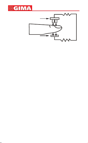
WARNING:
Uncomfortable or painful feeling may appear if using
the device ceaselessly, especially for the microcircula-
tion barrier patients. It is recommended that the sensor
should not be applied to the same nger for over 2 hours.
For the special patients, there should be a more prudent