SKF SGA-011 User manual

Assembly Instructions
SGA AND SG
DOSER GROUP
Date:
Document No.:
17.3.2023
SGA_SG_DOSERS_EN
Version: 5C
Read this manual before in-
stalling or commissioning the
product and keep it at hand for
later reference.

SKF DUOFLEX
DOSER GROUPS
DOSER GROUPS
(Original Operating and Service Manual according to EU Directive 2006/42/EC)
TABLE OF CONTENTS
1GENERAL ..................................................................................................................... 1
2MAINTENANCE .............................................................................................................. 1
3 SKF SAFETY INSTRUCTIONS .......................................................................................... 2
3.1 Safety instructions for the operator .................................................................................. 2
3.2 Safety instructions for maintenance, inspection and installation ................................................ 2
3.3 Warranty and liability ................................................................................................... 3
4 GENERAL DESCRIPTION ................................................................................................ 4
5DESIGN, SG DOSERS...................................................................................................... 4
6 OPERATION ................................................................................................................. 6
6.1 Dosers with two outlets ................................................................................................ 6
6.2 Dosers with one outlet ................................................................................................. 6
6.3 Unfastening and fastening dosers ................................................................................... 6
7ADJUSTMENTS.............................................................................................................. 7
7.1 General................................................................................................................... 7
8 TECHNICAL SPECIFICATIONS ....................................................................................... 10
8.1 Technical data......................................................................................................... 10
8.2 Connections.......................................................................................................... 10
8.3 Legend ................................................................................................................. 10
8.4 Base plate dimensioning and codes ......................................................................... 12
9 REMOVING FROM SERVICE .......................................................................................... 15
9.1 Temporary removing from service ................................................................................. 15
9.2 Final removing from service......................................................................................... 15
10 STORAGE ................................................................................................................. 15
11 SPARE PARTS ........................................................................................................... 15
11.1 Seal kits .............................................................................................................. 15
11.2 Repair kits............................................................................................................ 16
11.3 Other spare parts and dimensional drawings................................................................... 16
12 CONTACT INFORMATION............................................................................................. 16
APPENDICES 22 pcs.

1 (16)
DOSER GROUPS
1 GENERAL
The installation, operating and maintenance instructions in this manual conform to the EU Directive
2006/42/EC on machinery. The Operating and Service Manual is an integral part of operating the unit. Store it
for subsequent use.
This manual is copyright protected. Copying or distributing the document or parts of it with IT or data transfer
equipment or to networks without Oy SKF AB Muurame’s express permission is prohibited.
Oy SKF Ab Muurame reserves the right to make changes to the content and technical specifications in this
manual.
2 MAINTENANCE
If you have any technical questions, please do not hesitate to contact us:
Oy SKF Ab
P.O. Box 80, FI-40951 Muurame, FINLAND
Tel. +358 (0) 207 400 800
www.skf.com

2 (16)
3 SKF SAFETY INSTRUCTIONS
This operating and service manual contains basic information which must be observed when installing, operat-
ing and maintaining the unit. It is necessary for the installer and operator to read these instructions before in-
stallation and commissioning. Ensure that these instructions are always accessible to operating personnel.
In addition to these general safety instructions, the special safety instructions provided in other sections of this
document must be followed.
Safety signs
Symbol
Meaning
General risk of injury and damage
Voltage
Hot surface
Risk of slipping
Warnings and their meanings
WARNING
Meaning
DANGER!
Indicates risk of injury to people
WARNING!
Indicates danger to buildings, machines or environment
NOTE!
Indicates additional information
3.1 Safety instructions for the operator
Electricity-related risks must be prevented by following the current electrical safety regulations.
3.2 Safety instructions for maintenance, inspection and installation
The operator must ensure that all maintenance, inspection and installation work is carried out by authorized
and qualified specialists. This operating and service manual must be available to these staff members.

3 (16)
DANGER! Electrical connections must only be made by qualified electricians. Operating
voltage must be shut off before touching any parts with power supply. Operating voltage must
be shut off before opening any parts of the unit.
DANGER! Ensure that power to the unit is switched off during maintenance. Smoking and
producing open flames and sparks while working on or in the vicinity of hydraulic systems is
forbidden.
DANGER! Ensure that the unit is not pressurized during maintenance.
WARNING! Oils and water-polluting fluids must not be allowed to enter the soil, water cours-
es or sewer systems. Ensure that oils are disposed of safely and without harming the envi-
ronment. The relevant regulations in the country must be observed with regard to water pollu-
tion and oil disposal.
3.3 Warranty and liability
Oy SKF Ab Muurame will not assume any liability, nor will the warranty provided for the product cover any loss
in the following cases:
•The unit has not been used for its intended purpose.
•The unit has not been appropriately installed, de-commissioned or operated.
•The unit has been operated using impure lubricants or materials that have not been approved.
•The unit has been maintained or repaired incorrectly.
•Parts other than Oy SKF Ab's original spare parts have been used in the unit.
•The unit has been altered in ways that Oy SKF AB Muurame has not approved.
•Instructions for transportation and storage have not been followed.

4 (16)
4 GENERAL DESCRIPTION
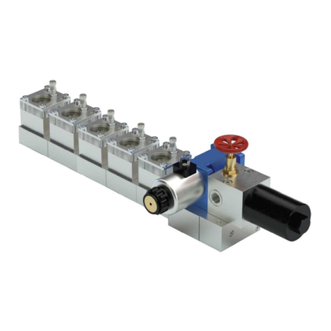
A doser group consist of a base plate (pos. 1) and one or more dosers attached to it (pos. 2). The base plate
divides the lubricant to the dosers, which feed the preset amount of lubricant to the lubrication points.
5 DESIGN, SG DOSERS
The man components of the doser are the body (2), double-seal piston (3), pilot valve (5), adjustment screw
(6) and indicator (7). Piston movement is controlled with the adjustment screw, and the indicator indicates
doser adjustment and functioning.
The lubrication outlet connections of the base plate are equipped with check valves (pos. 8). The design al-
lows dosing of small lubricant volumes from the doser because backflow is prevented.
461503

5 (16)
The indicator and adjustments in an SGA-xxx-WI -type doser are different from standard SG2 -type doser.
The indicator has no plastic cover and adjustments are made with adjusting plugs of varying sizes (pos. 9).
The indicator and adjustments in an SGA-xxx-NI -type doser are different from standard SG2 -type doser. The
indicator is replaced with a plug (pos. 10) and adjustments are made with adjusting plugs of varying sizes
(pos. 9).

6 (16)
6 OPERATION
6.1 Dosers with two outlets
Dosers with two outlets alternate dosing between opposite outlet connections between lubrication cycles.
The pressure in the line increases during pressurization and the doser pilot valve moves to its extreme posi-
tion, whereupon the lubricant moves the dosing piston. When the dosing piston moves, it pushes the lubricant
through the base plate check valve to the lubrication pipe or lubrication hose and further to the lubrication
point.
When the pumping starts again, the directional valve directs the lubricant to another main line whereupon the
doser pilot valve directs the lubricant to the opposite side of the dosing piston. When the dosing piston moves,
it pushes the lubricant through the base plate check valve and further to the lubrication point.
6.2 Dosers with one outlet
During normal sequential operation, dosers with one outlet always feed lubricant to the same outlet connec-
tion.
The design of the doser with one outlet is different from the doser with two outlets only by the design of the
pilot valve, which makes it possible to choose the outlet connection from the base plate. The opposite outlet
on the base plate must be plugged. The operation of the doser with one outlet is similar to the operation of
doser with two outlets.
6.3 Unfastening and fastening dosers
The dosers are removed from the base plate by loosening the two M6 hex head screws on top of the doser.
WARNING! When replacing dosers, make sure that there is no pressure in the system.
The dosers are fixed to the base plate with the M6 hex head screws delivered with the doser. Make sure that
the O rings between the doser and the base plate are in place before fixing the dosers.
WARNING! If the doser fastening screws are tightened too much, the operation of the doser
might be prevented. The maximum tightening torque is 8 Nm.

7 (16)
WARNING! When changing the doser, make sure that the type marking on the doser and the
number of outlets are identical. The last number on the doser type marking shows the number
of outlets.
7 ADJUSTMENTS
7.1 General
Lubricant dosage is adjusted by changing the piston’s range of movement from the adjustment screw or by
changing the dosing plug.
The SGA dosers are adjusted by twisting the adjustment screw with a hex key.
Adjust SG dosers by turning the hex screw under the metallic protective cap. The other end of the screw is
inside the doser cylinder and, when adjusted, it directly changes the piston’s range of movement.
The WI & NI doser’s lubricant dosage is adjusted by changing the movement of the piston using adjusting
plugs of varying lengths.
During both pressurizations of the lubrication cycle the doser with one outlet always feeds the lubricant to the
same lubrication point. The doser with two outlets feeds the lubricant to two different lubrication points. This
has been taken into account in the adjustment tables.
Table 1. Drawing numbers for adjustment values
Doser types (ZN, SS)
Drawing number
SGA-011, SGA-012
460120
SGA-11, SGA-12
460122
SGA-21, SGA-22
460123
SG-31, SG-32
460124
SG-41, SG-42
460126
SG-51, SG-52
460128

8 (16)
Adjustment of SGA dosers
1. Remove the protective plastic cap.
2. Make sure that the indicator is inside the doser body.
WARNING! The SGA doser is damaged if the adjustment screw is adjusted against the indi-
cator.
3. Twist the adjustment screw into the basic position where it touches the indicator lightly.
4. Check the adjustment value table for the correct number of adjustment screw turns for the required lubri-
cant dose.
5. Twist the screw as many times away from the doser body as specified in the table. The indicator body
has dosage grooves to facilitate adjustments.
6. Screw the protective cap back in its place.
Adjustment of SG dosers
1. Remove the protective metal cap from the top of the hex head screw.
2. Twist the hex head screw into the basic position at the level of the front surface of the thread on the body.
3. Check the adjustment value table for the correct amount of turns for the required lubricant dose.
4. Twist the hex head screw as many times away from the doser body as specified in the table. If the num-
ber is negative, the screw is twisted into the doser. The protective cap has dosage grooves to facilitate
adjustments.
5. Screw the protective cap back in its place.
Adjustment of WI and N dosers and dosages
1. Remove the doser’s end plug (pos. 9)
2. Place an end plug corresponding to the desired dosage on the doser and tighten it to 22.5 Nm.

9 (16)
Adjustment plugs SGA-01/1 Adjustment plugs SGA-2x
GREASE DENSITY 0.88 g/cm³
SGA 01/1 DOSER DOSAGE g/series ±5 %
NO.
NAME
SGA-012-ZN-WI
12387520
SGA-011-ZN-WI
12387470
SGA-12-ZN-WI
12387620
SGA-011-ZN-WI
12387570
4
PLUG SGA-01/1
0.8
1.6
1.41
2.82
1
ADJUSTMENT PLUG-3
SGA
0.6
1.2
1.06
2.12
2
ADJUSTMENT PLUG-2
SGA
0.4
0.8
0.7
1.4
3
ADJUSTMENT PLUG-1
SGA
0.2
0.4
0.35
0.7
SGA 2 DOSER DOSAGE g/series ±5 %
NO.
NAME
SGA-22-ZN-WI
12387720
SGA-21-ZN-WI
12387670
4
PLUG SGA-2
4.54
9.07
1
ADJUSTMENT PLUG-3
SGA 2
3.34
6.68
2
ADJUSTMENT PLUG-2
SGA 2
2.15
4.29
3
ADJUSTMENT PLUG-1
SGA 2
0.98
1.98

10 (16)
8 TECHNICAL SPECIFICATIONS
8.1 Technical data
Table 2. Technical specifications for doser group
Quantity
Value
Unit
Description
t
-25…+80
°C
Operating temperature range
pmax
250
300
bar
max. pressure, 01-dosers
max. pressure, other dosers
M
8
Nm
doser tightening torque to the base plate
8.2 Connections
Inlet and outlet connections are in the base plate.
Inputs
•lubricant (2 pcs), header piping inlets, female thread R 1/4” or NPT 1/4”
Outputs
•lubricant (2 pcs), header piping outlets, female thread R 1/4” or NPT 1/4”
•lubricant (2-12 pcs), lubrication piping outlets, female thread R 1/8” or NPT 1/8”
8.3 Legend
Table 3. Doser designation
SGA-xxy-zz-ww
Abbreviation
Description
SG:
SG
Lubrication system type: SKF DuoFlex
A:
A
small doser (sizes 01, 1 and 2)
no symbol
small doser (sizes 3, 4 and 5)
xx:
01
doser size 01
1
doser size 1
2
doser size 2
3
doser size 3
4
doser size 4
5
doser size 5
y:
1
one outlet
2
two outlets
zz:
ZN
doser material:
zinc-coated and yellow-passivated steel
SS
doser material:
acid-proof steel AISI-316
ww:
no symbol
standard doser
WI
doser with a steel indicator
NI
doser without indicator

11 (16)
Example:
SGA-012-SS
Small doser
Doser size: size 01
Outlet number: 2 outlets
Doser material: acid-proof steel AISI 316
Lubrication system type: SKF DuoFlex
Table 4. Symbols of base plates
BPSG-xx-yy-U
Abbreviation
Description
BP:
BP
Base Plate
SG:
SG
Lubrication system type: SKF DuoFlex
xx:
01
1-place base plate
02
2-place base plate
03
3-place base plate
04
4-place base plate
05
5-place base plate
06
6-place base plate
yy:
AL
Base plate material,
anodized aluminium
SS
Base plate material,
acid-proof steel, AISI-316
U:
no symbol
connections, BSP G threads
U
Connections, NPT threads
Example:
BPSG-03-AL
Base Plate
Lubrication system type, SKF Dual line
Base plate size, 3 doser slots
Base plate material, aluminium
Connections: BSP G threads

12 (16)
8.4 Base plate dimensioning and codes
Table 5. Base plate dimensioning
Model
A
B
Number
BPSG-01-AL
46
60
12383250
BPSG-02-AL
78
92
12383300
BPSG-03-AL
110
124
12383350
BPSG-04-AL
142
156
12383400
BPSG-05-AL
174
188
12383450
BPSG-06-AL
206
220
12383500
BPSG-01-SS
46
60
12384300
BPSG-02-SS
78
92
12384350
BPSG-03-SS
110
124
12384400
BPSG-04-SS
142
156
12384450
BPSG-05-SS
174
188
12384500
BPSG-06-SS
206
220
12384550

13 (16)
Table 7. U model dimensions
Model
A
B
Number
BPSG-01-AL-U
46 (1 13/16")
60 (2 23/64")
12384000
BPSG-02-AL-U
78 (3 5/64")
92 (3 5/8")
12384050
BPSG-03-AL-U
110 (4 21/64")
124 (4 7/8")
12384100
BPSG-04-AL-U
142(5 19/32")
156 (6 9/64")
12384150
BPSG-05-AL-U
174 (6 27/32")
188 (7 13/32")
12384200
BPSG-06-AL-U
206 (8 7/64")
220 (8 21/32")
12384250
BPSG-01-SS-U
46 (1 13/16")
60 (2 23/64")
12384600
BPSG-02-SS-U
78 (3 5/64")
92 (3 5/8")
12384650
BPSG-03-SS-U
110 (4 21/64")
124 (4 7/8")
12384700
BPSG-04-SS-U
142(5 19/32")
156 (6 9/64")
12384750
BPSG-05-SS-U
174 (6 27/32")
188 (7 13/32")
12384800
BPSG-06-SS-U
206 (8 7/64")
220 (8 21/32")
12384850

14 (16)
Table 8. B model dimensioning
Model
A
B
Number
BPSG-01-AL-B
46
60
12383550
BPSG-02-AL-B
78
92
12383560
BPSG-03-AL-B
110
124
12383570
BPSG-04-AL-B
142
156
12383580
BPSG-05-AL-B
174
188
12383590
BPSG-06-AL-B
206
220
12383600

15 (16)
9 REMOVING FROM SERVICE
9.1 Temporary removing from service
The system can be temporarily shut down by disconnecting it from electrical, pressurised air and hydraulic
outlets. For further information, see section “General description” of this manual. For temporary removal from
service, see also section ”Storage”. To restart the system, see the ”Operation” and “Technical specification”
sections.
9.2 Final removing from service
All relevant country-specific instructions and regulations regarding the decommissioning and disposal of
contaminated equipment must be followed when decommissioning the product.
WARNING! Lubricants can contain chemicals that can contaminate the soil and the water
system. Lubricants must be disposed of correctly. Follow the national instructions
and regulations for disposal and recycling.
Oy SKF AB will receive products it has delivered and take care of their appropriate disposal. Oy SKF AB has
the right to charge for expenses that are not related to disposal and recycling.
10 STORAGE
The products must be stored as follows:
•The storage space must be dry, dust-free and well ventilated
•The maximum storage time is 24 months
•The storage temperature must be 10–40°C
•Avoid exposure to direct sunlight and thermal radiation
•Store the products clear of the ground or floor
•Protect the products from mechanical shocks, corrosion and dust
11 SPARE PARTS
11.1 Seal kits
See SGA-01 doser seal kit (drawing 460670).
See SGA-1 doser seal kit (drawing 460671).
See SGA-2 doser seal kit (drawing 460672).
See LG-3-4-5 doser seal kit (drawing 360502).

16 (16)
11.2 Repair kits
See SGA-01-ZN doser repair kit (drawing 460508).
See SGA-01-SS doser repair kit (drawing 460509).
See SGA-1-ZN doser repair kit (drawing 460510).
See SGA-1-SS doser repair kit (drawing 460511).
See SGA-2-ZN doser repair kit (drawing 460512).
See SGA-2-SS doser repair kit (drawing 460513).
See SGA-3-4-5-ZN-SS doser repair kit (drawing 360739).
11.3 Other spare parts and dimensional drawings
See SGA and SG doser group spare parts (drawing 461505).
See WI dosers SGA-011, SGA-012, SGA-11 & SGA-12 dimensions and spare parts (drawing 361261)
See WI dosers SGA-2 dimensions and spare parts (drawing 361344)
See NI dosers SGA-011, SGA-012, SGA-11 & SGA-12 dimensions and spare parts (drawing 361463)
See WI dosers SGA-2 dimensions and spare parts (drawing 361462)
12 CONTACT INFORMATION
Oy SKF Ab
P.O. Box 80
40951 MUURAME
FINLAND
Tel.: +358 20 7400 800
Fax: +358 20 7400 899
www.skf.com

HeH
1/1
FINLAND
MUURAME
Oy SKF Ab
12387460
SGA-011-ZN
12387510
SGA-012-ZN
12386560
12386610
12388800
12388840
12388850
SGA-011-ZN,SGA-012-ZN
SGA-011-SS,SGA-012-SS
3.2.1998
LeL
WITH THE ADJ. SCREW IN THE COMPLETELY
IN POSITION TURNS COUNTERCLOCKWISE
WITH THE ADJ. SCREW IN THE COMPLETELY
IN POSITION TURNS COUNTERCLOCKWISE
CODE
TYPE
DESCRIPTION
DOSAGE RANGE
ONE LUBE POINT DOSER ZN
TWO LUBE POINT DOSER ZN
ONE LUBE POINT DOSER SS 316
TWO LUBE POINT DOSER SS 316
0.30-1.45 G/CYCLE
0.15-0.70 G/CYCLE
0.30-1.45 G/CYCLE
0.15-0.70 G/CYCLE
SAFE-R SEAL KIT
REPAIR KIT FOR ZN DOSERS
REPAIR KIT FOR SS 316 DOSERS
DOSERS INCLUDE ALL NECESSARY FASTENING SCREWS AND PLUGS
DOSAGE: G/LUBRICATION CYCLE ±5%
GROOVE 0
GROOVE 1
GROOVE 2
GROOVE 3
GROOVE 4
ADJUSTMENT GRAPH FOR SGA-011 DOSER ADJUSTMENT GRAPH FOR SGA-012 DOSER
DOSAGE: G/LUBRICATION CYCLE ±10%
SGA-011-SS
SGA-012-SS
SGA-01-KIT1
SGA-01-ZN-KIT2
SGA-01-SS-KIT2
4
0
0.0
0.1
0.2
0.3
0.4
0.5
0.6
0.7
0.8
0.9
1.0
1.1
1.2
1.3
1.4
1.5
2
4
6
8
10
12
14
16
18
20
22
24
26
0
0.0
0.05
0.1
0.15
0.2
0.25
0.3
0.35
0.4
0.45
0.5
0.55
0.6
0.65
0.7
0.75
2
4
6
8
10
12
14
16
18
20
22
24
26
DOSER
GROOVE 4
GROOVE 3
GROOVE 2
GROOVE 1
GREASE DENSITY 0.88g/cm3
HEX KEY
REQUIRED
GROOVE 4
GROOVE 3
GROOVE 2
GROOVE 1
460120 B

26
24
22
20
18
16
14
12
10
8
6
4
2
0
0.0
0.2
0.4
0.6
0.8
1.0
1.2
1.4
1.6
1.8
2.0
2.2
2.4
2.6
1.3
1.2
1.1
1.0
0.9
0.8
0.7
0.6
0.5
0.4
0.3
0.2
0.1
0.0
0
2
4
6
8
10
12
14
16
18
20
22
24
26
WITH THE ADJ. SCREW IN THE COMPLETELY
IN POSITION TURNS COUNTERCLOCKWISE
WITH THE ADJ. SCREW IN THE COMPLETELY
IN POSITION TURNS COUNTERCLOCKWISE
CODE
TYPE
DESCRIPTION
DOSAGE RANGE
ONE LUBE POINT DOSER ZN
TWO LUBE POINT DOSER ZN
ONE LUBE POINT DOSER SS 316
TWO LUBE POINT DOSER SS 316
SAFE-R SEAL KIT
REPAIR KIT FOR ZN DOSERS
REPAIR KIT FOR SS 316 DOSERS
DOSERS INCLUDE ALL NECESSARY FASTENING SCREWS AND PLUGS
GREASE DENSITY 0.88g/cm3
DOSAGE: G/LUBRICATION CYCLE – 5%
4
12387560
SGA-11-ZN
12387610
SGA-12-ZN
12386660
SGA-11-SS
SGA-12-SS
12386710
12388810
SGA-1-KIT1
SGA-1-ZN-KIT2
12388860
12388870
SGA-1-SS-KIT2
3.2.1998
LeL
128
GROOVE 1
GROOVE 2
GROOVE 0
GROOVE 3
GROOVE 3
GROOVE 2
GROOVE 1
GROOVE 1
GROOVE 2
GROOVE 3
0.25-1.25g/ CYCLE
0.50-2.55g/ CYCLE
0.25-1.25g/ CYCLE
0.50-2.55g/ CYCLE
REQUIRED HEX. KEY
ADJUSTMENT GRAPH FOR SGA-11 DOSER
ADJUSTMENT GRAPH FOR SGA-12 DOSER
DOSAGE: G/LUBRICATION CYCLE – 5%
SGA-11-ZN, SGA-12-ZN
SGA-11-SS, SGA-12-SS
DOSER
460122 A
DESIGNED
ITEM
DESCRIPTION
DETAIL DRAW
MATERIAL
DIM,PATT
QTY
MATERIAL DESCRIPTION
(WEIGHT KG)
SPECIFICATION OF PART
PREVIOUS DRG
FUTURE DRG
DATE
SCALE
DRAWING NUMBER
DRAWN
CODE / QTY / PART
Oy SKF Ab
MUURAME
FINLAND
SHEET/SHEETS
This manual suits for next models
11
Table of contents
Other SKF Control Unit manuals

SKF
SKF DCV5-4+924 Manual

SKF
SKF BCU User manual

SKF
SKF SCU 1 User manual

SKF
SKF MAXILUBE MAX 230-IF105 Series User manual

SKF
SKF LC502 User manual

SKF
SKF Lincoln 758 Product manual

SKF
SKF SMBM-X Series User manual

SKF
SKF BPSG2-PTA-MOD-EX-SS Manual

SKF
SKF Lincoln 85307 User manual

SKF
SKF Lincoln 85307 User manual