1. GENERAL
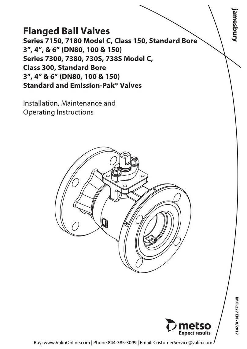
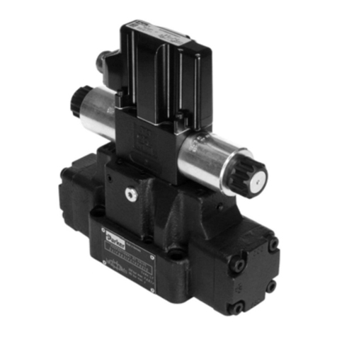
This instruction manual contains important information
regarding the installation, maintenance, and troubleshooting
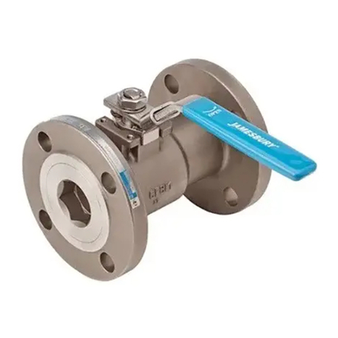
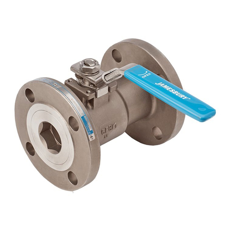
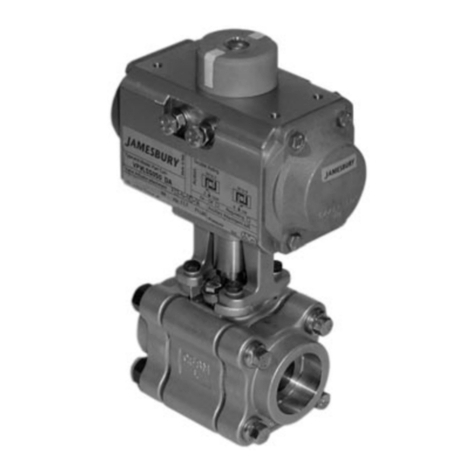
of Jamesbury® Standard Bore Series 7150, 730S, and 7300
Flanged Ball Valves equipped with Kerotest Handles. Please
read the instructions carefully and save them for future
reference.
WARNING
FOR YOUR SAFETY, IT IS IMPORTANT THAT THE FOLLOWING
PRECAUTIONS BE TAKEN PRIOR TO REMOVAL OF THE VALVE FROM
THE LINE OR BEFORE ANY DISASSEMBLY.
1. WEAR ANY PROTECTIVE CLOTHING OR EQUIPMENT
NORMALLY REQUIRED WHEN WORKING WITH THE FLUID
INVOLVED.
2. DEPRESSURIZE THE LINE AND CYCLE THE VALVE AS FOLLOWS:
A. PLACE THE VALVE IN THE OPEN POSITION AND DRAIN THE
LINE.
B. CYCLE THE VALVE TO RELIEVE RESIDUAL PRESSURE IN THE
BODY CAVITY BEFORE REMOVAL FROM THE LINE.
C. AFTER REMOVAL AND BEFORE ANY DISASSEMBLY,CYCLE
THE VALVE AGAIN SEVERAL TIMES.
3. SEAT AND BODY RATINGS THE PRACTICAL AND SAFE USE
OF THIS PRODUCT IS DETERMINED BY BOTH THE SEAT AND
BODY RATINGS.READ THE NAME TAG AND TRY TO CHECK
BOTH RATINGS. THIS PRODUCT IS AVAILABLE WITH A VARIETY
OF SEAT MATERIALS. SOME OF THE SEAT MATERIALS HAVE
PRESSURE RATINGS THAT ARE LESS THAN THE BODY RATINGS.
ALL OF THE BODY AND SEAT RATINGS ARE DEPENDENT ON
VALVE TYPE AND SIZE, SEAT MATERIAL, AND TEMPERATURE.
DO NOT EXCEED THESE RATINGS.
1.1 Installation
Flow through this Jamesbury valve can be in either
direction. It is recommended, however, that the valve be
installed with the insert facing upstream.
IMPORTANT: The valve should be tightened between
anges using appropriate gaskets and fasteners for the
service, in compliance with applicable piping codes and
standards.
2. MAINTENANCE
Although Metso’s Jamesbury valves are designed to work
under severe conditions, proper preventative maintenance
can signicantly help to prevent unplanned downtime and
in real terms reduce the total cost of ownership. Metso
recommends inspecting valves at least every ve (5) years.
The inspection and maintenance frequency depends on
the actual application and process condition.
2.1 Kerotest Handle Disassembly
NOTE: If complete disassembly becomes necessary,
replacement of all seats and seals is recommended.
1. When performing any work on this valve, use normal
safety precautions to protect yourself against residual
uid or trapped pressure in the line.
2. Depressurize and drain the line. CYCLE THE VALVE
SEVERAL TIMES BEFORE DOING ANY WORK. This will
relieve any pressure still inside the valve.
3. Remove the valve from the line and cycle the valve
several times again leaving in the closed position.
4. Place the valve in the open position.
5. Disassembly of Kerotest Handle.
A. Remove set screw (28) loosen handle (11). DO NOT
REMOVE.
B. Loosen four cover fasteners (22). DO NOT REMOVE.
C. Remove handle (11) from the housing (9).
D. Remove bearing (25) from housing and remove
gasket (27) from the handle.
E. Remove four fasteners (22). NOTE: With weld-on
bonnets remove the four nuts (23) as well.
F. Slip cover (8) over housing (9) and remove.
G. Remove housing (9) from bellows (7).Remember
that the I.D. of the housing mates with O-ring (16)
of the bonnet to provide an O-ring seal.
H. Remove bearing (18) from cover (8).
I. Remove bellows screws (21).
J. Remove bellows (7). Take care not to scratch or
kink bellows.
K. Remove bearing (26) from end of handle stem (4).
L. Remove handle stem (4).
M. Remove housing seal O-ring (16) from bonnet hub.
N. Remove bearing (18) from bonnet.
O. Remove bellows seal O-ring (15) from bonnet face.
P. Remove handle bearing (14) from bonnet bore.
Q. NOTE: With bolt-on bonnet extensions, remove
the four bonnet screws (20),the bonnet extension
(10) and the bonnet seal (17).
2.2 Disassembly of Valve.
Tools needed to disassemble Jamesbury valves such as
the “insert eld wrench”mentioned in step B and shown
in (Figure 6), may be ordered as (kit #40-044-0154-00)
for 3” & 4” (DN 80 & 100)Series 7000, and (kit #40-060-
9022-00) for 6” (DN 150) Series 7000 from your local Metso
Automation distributor.
NOTE: If complete disassembly becomes necessary,
replacement of all seats and seals is recommended. Refer to
the Repair Kit chart (See Table 1 in IMO-299).
1. Follow the steps in the WARNING Section before
performing any work on the valve.
IMO 11/17
IMO-261 EN 3


