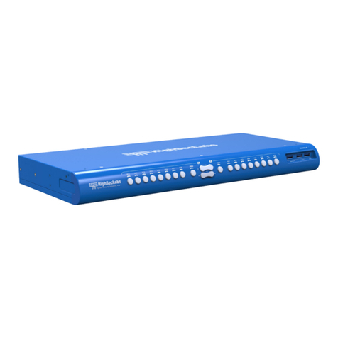
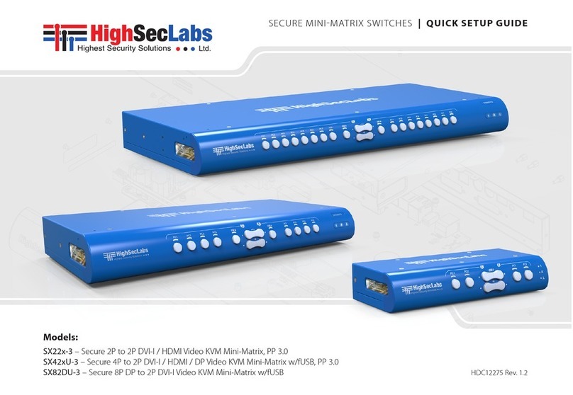
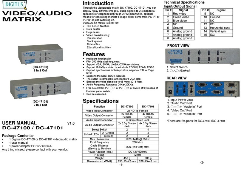
High Sec Labs Mini-Matrix SX42PH-4 User manual

Models:
SX42PH/PHU-4 – Secure 4P to 2P DP/HDMI Video KVM Mini-Matrix w/fUSB, PP 4.0
SX82PH/PHU-4 – Secure 8P to 2P DP/HDMI Video KVM Mini-Matrix w/fUSB, PP 4.0
SX82PHU-4T – Secure 8P to 2P DP/HDMI Video KVM Mini-Matrix w/fUSB, PP 4.0 Tempest HLT31845 Rev. 1.2
SECURE MINIMATRIX SWITCHES | USER MANUAL

1
HSL Secure Mini-Matrix User Manual
TABLE OF CONTENTS
SECTIONS
Table of Contents 123
Introduction .......................................................... 2
HSL Secure Mini-Matrix........................................................2
Package Contents ............................................................3
Before Installation .............................................................3
Tamper-Evident Labels ........................................................4
Active Anti-Tampering System ................................................4
Mini-Matrix Specifications.....................................................5
Installation............................................................ 6
Installing the Mini-Matrix......................................................6
Operation............................................................. 9
Operating the Mini-Matrix ....................................................9
4-Port Presets . . . . . . . . . . . . . . . . . . . . . . . . . . . . . . . . . . . . . . . . . . . . . . . . . . . . . . . . . . . . . . . .12
8-Port Presets ............................................................... 22
Advanced Presets ........................................................... 29
Keyboard shortcut options...................................................31

2
HSL Secure Mini-Matrix User Manual
INTRODUCTION
SECTIONS
Table of Contents 2 3
1
HSL Secure Mini-Matrix
Optimizes user experience when working with multiple computers.
Enables you to view and control two out of four computers, at the same
time, while securely sharing keyboard, video, mouse, audio, and USB
devices.
The Mini-Matrix KVM switch provides increased productivity in
challenging multi-computer environments, where users are required
to view and interact with several computers, while maintaining the
highest isolation between computers and peripherals.
Prevents the need for purchasing and installing dedicated, per
computer peripheral sets.
This guide refers to the following models:
SX42PH-4 - Secure 4P to 2P DP/HDMI Video KVM Mini-Matrix, PP 4.0
SX42PHU-4 - Secure 4P to 2P DP/HDMI Video KVM Mini-Matrix w/fUSB, PP 4.0
SX82PH-4 - Secure 8P to 2P DP/HDMI Video KVM Mini-Matrix, PP 4.0
SX82PHU-4 - Secure 8P to 2P DP/HDMI Video KVM Mini-Matrix w/fUSB, PP 4.0
SX82PHU-4T - Secure 8P to 2P DP/HDMI Video KVM Mini-Matrix w/fUSB, PP 4.0,
Tempest

3
HSL Secure Mini-Matrix User Manual
INTRODUCTION
SECTIONS
Table of Contents 2 3
1
Package Contents
Inside the product packaging is the following:
Model Description Qty
SX42xU-4
Secure 4P to 2P DP/HDMI Video KVM Mini-
Matrix w/fUSB, PP 4.0 1
Power cable 1
SX82xU-4
Secure 8P to 2P DP/HDMI Video KVM Mini-
Matrix w/fUSB, PP 4.0 1
Rack mount kit 1
Power cable 1
Before Installation
Unpacking the Product
Before opening the product’s sealed packaging, inspect the seal’s
condition to assure that the product was not accessed or tampered
with during delivery. If the packaging seal looks suspicious contact the
HSL support team and do not use the product.
After seal removal, inspect the packaging content to verify that the
required components are included. See the packaging content list on
page 4 above.
After the Mini-Matrix KVM Switch is removed from its packaging
materials, carefully inspect the tampering-evident label to assure that
product is properly sealed. If the label is damaged or missing, contact
HSL support and do not use the product.

4
HSL Secure Mini-Matrix User Manual
INTRODUCTION
SECTIONS
Table of Contents 2 3
1
Tamper-Evident Labels
•The Mini-Matrix KVM Switch uses a holographic tamper evident label
to provide visual indications in case of enclosure intrusion attempts.
These labels indicate white dots or the text “VOID”, once removed.
When opening the product’s packaging, inspect the tampering
evident label.
•If for any reason, one or more tamper-evident labels are missing,
appear disrupted, or look different than the example shown here,
please call HSL Technical Support and avoid using that product.
HSL Holographic Tamper-Evident Label
Active Anti-Tampering System
•The Mini-Matrix KVM Switch is equipped with an always-on active
anti-tampering system. If mechanical intrusion is detected by this
system, the switch is permanently disabled and the LED blinks
continuously.
•If the product indicates a tampered state (all LEDs blinking) - call HSL
Technical Support and avoid using the product.

5
HSL Secure Mini-Matrix User Manual
INTRODUCTION
SECTIONS
Table of Contents 2 3
1
Mini-Matrix Specifications
Part Number SX42PH/PHU-4 SX82PH/PHU-4 SX82PHU-4T
No. of Sources 488
Console Ports
Displays 2 x DP/HDMI 2 x DP/HDMI 2 x DP/HDMI
Max Output Resolution UHD 4K resolutions up to 3840x2160 @ 60 Hz UHD 4K resolutions up to 3840x2160 @ 60 Hz UHD 4K resolutions up to 3840x2160 @ 60 Hz
Mouse and Keyboard USB Type A USB Type A USB Type A
Audio Jack 3.5 mm Jack 3.5 mm Jack 3.5 mm Jack
fUSB Port USB Type A (U) USB Type A (U) USB Type A
Computer Ports
Display Type 4 x DP/HDMI 8 x DP/HDMI 8 x DP/HDMI
Max Resolution UHD 4K resolutions up to 3840x2160 @ 60 Hz UHD 4K resolutions up to 3840x2160 @ 60 Hz UHD 4K resolutions up to 3840x2160 @ 60 Hz
Mouse and Keyboard USB Type B USB Type B USB Type B
Audio Jack 3.5 mm Jack 3.5 mm Jack 3.5 mm Jack
fUSB Port USB Type B (U) USB Type B (U) USB Type B
Physical
Dimensions 342 x 148 x 42 mm / 13.4 x 5.8 x 1.6 inches 440 x 192 x 48 mm / 17.3 x 7.5 x 1.9 inches 440 x 192 x 48 mm / 17.3 x 7.5 x 1.9 inches
Weight 1.6 kg (3.5 lbs) 2.6 kg (5.7 lbs) 2.6 kg (5.7 lbs)
Power
Power Requirements 12V DC, 2.5A 35W Max 35W Max
AC Input 100 to 240V AC 100 to 240V AC 100 to 240V AC
Power Type External Internal Internal
Certification
Security Compliant with NIAP Common Criteria PP4.0 for
Peripheral Sharing Switch (PSS) devices
Compliant with NIAP Common Criteria PP4.0 for
Peripheral Sharing Switch (PSS) devices
Compliant with NIAP Common Criteria PP4.0 for
Peripheral Sharing Switch (PSS) devices, Tempest
Level B Compliant

6
HSL Secure Mini-Matrix User Manual
INSTALLATION
SECTIONS
Table of Contents 1 3
2
Installing the Mini-Matrix
Step 1 – Cable Installation
1. Connect the console port peripherals:
•Connect the video displays to the Mini-Matrix primary and
secondary display ports.
Note: It is highly recommended to use identical primary and secondary
display models. EDID information is taken from the primary console display
port (#1) and sent to all connected computers. When using non-identical
displays, connect the smaller display to the primary console display port.
•Connect keyboard, mouse, and audio peripherals to
the Mini-Matrix console ports. These are shared
securely between all sources.
•Connect a smartcard/biometric reader to the
Mini-Matrix’s console fUSB secure port, to
support user authentication across multiple
isolated sources.
2. Connect the computer/source channel ports:
For each source, connect the video, keyboard,
mouse, fUSB, and audio cables to the Mini-Matrix
source ports.
3. To receive dual-screen support:
Download and install HSL’s multi-display driver onsource computers
that have multiple screens (currently available only for Windows)
(https://highseclabs.com/downloads/km-multi-display-drivers/).
CONSOLE PORTS COMPUTER/SOURCE PORTS
Smart-Card
Reader Computers
fUSB Cable
Audio Cable
Mouse Cable
Display Cable
Keyboard Cable
Audio Keyboard Mouse
1 2 3 4
Right DisplayLeft Display

7
HSL Secure Mini-Matrix User Manual
INSTALLATION
SECTIONS
Table of Contents 1 3
2
Step 2 – Power ON the Mini-Matrix
1. Turn ON all the PCs.
2. Connect the power supply and power ON the
Mini-Matrix (approximate boot time is 10
seconds).
The Mini-Matrix boots into duplicate-mode,
where source number 1 is presented on
both displays.
Note: In case no picture is presented after powering ON, switch between the
primary and secondary displays, or connect an alternate display, or perform a
reset to factory default.
Move mouse to switch PCs
PC #4
Top Secret
PC #1
Internet Multiple Sources
Speakers
Single
Keyboard & Mouse
SECURE
MINI-MATRIX
SECURE
MINI-MATRIX
N
I
A
P
P
P
P
S
S
4
.
0
C
O
M
P
L
I
A
N
T
C
O
M
M
O
N
C
R
I
T
E
R
I
A

8
HSL Secure Mini-Matrix User Manual
INSTALLATION
SECTIONS
Table of Contents 1 3
2
Step 3 – Reset to Factory Defaults
Reset to factory defaults clears the device settings and restores the
device to its original configuration. You have the following options:
•System reset: Clears behavioral characteristics such as mouse
settings and display presets. Type the: { L Ctrl | L Ctrl | F11| r } key
combination.
•Complete reset: Clears all device settings and resets to factory
defaults. From the Terminal menu, select the “Reset to Factory
Defaults” option (refer to terminal mode guide).
Important Notes:
1. Always use the left control key (Ctrl) unless otherwise specified.
2. Keyboard shortcut keys are to be pressed sequentially
3. Do not use the numeric keypad for toggling shortcuts, unless
otherwise specified.
4. ALL KEYBOARD SHORTCUTS REFER TO QWERTY KEYBOARDS. For
non-qwerty keyboards, keep using the QWERTY layout.
`
~
1
!
2
@
3
#
4
$
5
%
6
^
7
&
8
*9
(
0
)
-
_
=
+
Tab Q W E R T Y U I O P [
{
]
}
Caps A S D F G H J K L :
;‘
“
Shift
CtrlCtrl Alt Alt
Delete
Enter
\
|
Shift
Ctrl
é
çêè 0
123
456
789-
+
Num
Lock
Enter
=/*
,
Insert
Delete
Home
End
Page
UP
Page
Down
Z X C V B N M ?
/
>
.
<
,

9
HSL Secure Mini-Matrix User Manual
OPERATION
SECTIONS
Table of Contents 123
Operating the Mini-Matrix
Step 1 – Display and Control Options
Display and control options define which source to display and control
on each screen. Source selection is done using the source selection
buttons on the front panel or via the DCU (dedicated control unit) port.
1234 5 6 7 8 9
1No. 1-4 Computer No. 1 display Push-Button
2Keyboard and Mouse toggle
3fUSB Freeze toggle
4Audio Freeze toggle
5Keyboard and Mouse toggle
6No. 1-4 Computer No. 2 display Push-Button
7Num Lock LED
8Caps Lock LED
9Scroll Lock LED
•Use the source selection panels to choose which source to display
on each screen.
•The left panel controls which source to display on the primary display,
while the right panel controls the secondary display. For example, as
seen in the illustration, when #1 is selected on the primary panel
and #3 is selected on the secondary panel, the selected sources are
presented accordingly.
•A source can be duplicated, by selecting its number on both panels.
•By default, mouse, keyboard, audio, and fUSB peripherals follow the
display association.
•Independently switch the video/usb /audio /keyboard and mouse
ports between computers.
•Use the front-panel push buttons to independently switch the video/
usb /audio/keyboard and mouse ports between the primary and
secondary computers. This is useful for various scenarios, for example:
•It is possible to switch every peripheral device group
independently between the two projected computers.
•Video, HID (keyboard and Mouse), audio, and fUSB can be
switched independently.
•When a user wants to listen to audio originating from one
computer while, working on another computer.
•Additional options are
described later under
the Advanced Presets
section.
Monitor 1 Monitor 2
Keyboard & Mouse
PC #1
PC #1 PC #2 PC #3 PC #4
PC #3
Screen Border
Mouse Cursor Path
Mouse Cable
Display Cable
Keyboard Cable
Controlled PC Screens

10
HSL Secure Mini-Matrix User Manual
OPERATION
SECTIONS
Table of Contents 123
Step 2 – Relative vs. Absolute Mouse
The Mini-Matrix is set up with the following mouse settings:
•Relative mouse (default) confines the mouse movement to the
screen of each selected computer. To switch the mouse between
sources, use the front panel push buttons.
•Absolute mouse (Virtual Display Technology - VDT) enables
switching the mouse between sources, by moving the mouse
cursor across display boarders.
Cursor Navigation (Virtual Display Technology - VDT):
•With cursor navigation, the user can move from one highly
isolated computer system to another, by simply moving the
mouse cursor across display borders.
•Once the cursor crosses the display border, the keyboard, mouse,
audio, and USB mapping switches to the computer that is
connected to that display.
•No need to push any buttons.
Note: It is possible to enable a safety trigger for more controlled
switching between channels. Using: L-Ctrl | L-Ctrl | F11 | L requires
pressing the left Ctrl button while dragging the mouse to switch
channels.
How to define the mouse state
•Use the key combination { L Ctrl | L Ctrl | F11 | c } to enable
absolute mouse (VDT).
•Use the key combination { L Ctrl | L Ctrl | F11 | b } to enable
relative mouse (this is the default mode).
PC #1 PC #2
Screen border
Mouse cursor movement path

11
HSL Secure Mini-Matrix User Manual
OPERATION
SECTIONS
Table of Contents 123
Step 3 – Predefined Display Layouts (Presets)
What are presets?
•Presets reflect the layout and boarders of computer displays to
the Mini-Matrix.
•The Mini-Matrix includes six predefined presets, described below.
What are presets for?
•Presets enable the Mini-Matrix to correctly associate the mouse
with each source, based on the physical display positioning and
the respective number of displays associated with each source.
•Presets enable cursor navigation switching that enables switching
control between PCs, by moving the mouse cursor across display
boarders.
How to switch between presets?
•Use the key combination { L Ctrl | L Ctrl | F11 | F1-to-F10 } to
toggle between presets.
To enable absolute-mouse prior to working with presets, type:
{ L Ctrl | L Ctrl | F11 | c }.
Note: Additional presets are possible using an external configuration
tool. For more information, contact HSL support.

12
HSL Secure Mini-Matrix User Manual
OPERATION 4PORT ADVANCED PRESETS
SECTIONS
Table of Contents 123
Preset #1 (default) { L Ctrl | L Ctrl | F11 | F1 }
(applicable for both 4P and 8P)
Setup:
•Connect PCs to the computer/source ports: Connect each
computer’s display, USB, and audio cables to the corresponding
computer port.
•Connect peripherals to the console ports: Connect two displays,
keyboard, mouse, and speaker/headphone to the console ports.
To use:
•Choose which computer to display on each screen, using the
source selection panels.
•The left panel controls which computer to display on the primary
display. The right panel controls the secondary display.
•Seamlessly switch between computers, by moving themouse
cursor across display boarders.
•Keyboard, audio, and USB peripherals follow the mouse
association.
Monitor 1 Monitor 2
Keyboard & Mouse
PC #1
PC #1 PC #2 PC #3 PC #4
PC #3
Screen Border
Mouse Cursor Path
Mouse Cable
Display Cable
Keyboard Cable
Controlled PC Screens

13
HSL Secure Mini-Matrix User Manual
OPERATION 4PORT ADVANCED PRESETS
SECTIONS
Table of Contents 123
Preset #2 { L Ctrl | L Ctrl | F11 | F2 }
(applicable for both 4P and 8P)
•Two displays/monitors (monitors 1 and 2) are connected to the
primary and secondary console ports.
•Four single-display sources (PCs 1-4) are connected to the Mini-
Matrix source ports 1-4.
•Display/monitors are aligned vertically so that the secondary
screen is on top of the primary screen.
•The VDT mouse cursor movement axis is vertical.
Highlights:
•Use the source selection panel to choose which sources to display.
•Switch between selected sources, by dragging the mouse cursor
vertically.
Monitor 1
Monitor 2
PC #1
PC #3
Keyboard & Mouse
PC #1 PC #2 PC #3 PC #4
Screen Border
Mouse Cursor Path
Mouse Cable
Display Cable
Keyboard Cable
Controlled PC Screens

14
HSL Secure Mini-Matrix User Manual
OPERATION 4PORT ADVANCED PRESETS
SECTIONS
Table of Contents 123
Preset #3 { L Ctrl | L Ctrl | F11 | F3 }
•Two displays/monitors (monitors 1 and 2) are connected to the
primary and secondary console ports.
•One display/monitor (monitor 3) is connected directly to the PC #1
primary-display adapter.
•The PC #1 secondary-display adapter is connected to the Mini-
Matrix source port 1.
•Three single-display sources (PC 2, 3, and 4) are connected to the
Mini-Matrix source ports 2, 3, and 4.
•All displays/monitors are aligned horizontally so that the primary
screen of PC#1 is on the left, the Mini-Matrix primary screen is in
the middle, and the Mini-Matrix Secondary screen is on the right.
•The VDT mouse cursor movement axis is horizontal.
Note: Any externally connected display should have the same native
resolution of the primary display connected directly to the matrix.
Download and install HSL’s Multi Display Driver on source computers
that have multiple screens (currently available for Windows only).
Direct Connection
Keyboard & Mouse
PC #1 PC #2 PC #3 PC #4
Screen Border
Mouse Cursor Path
Mouse Cable
Display Cable
Keyboard Cable
Controlled PC Screens
Monitor 3 Monitor 1
PC #1 Primary PC #1 Secondary
Monitor 2
PC #3

15
HSL Secure Mini-Matrix User Manual
OPERATION 4PORT ADVANCED PRESETS
SECTIONS
Table of Contents 123
Preset #4 { L Ctrl | L Ctrl | F11 | F4 }
•Same as Preset #3 when source #4 is directly connected to a primary
screen.
•Two display/monitors (monitors 1 and 2) are connected to the
primary and secondary console ports.
•One display/monitor (monitor 4) is connected directly to the PC #4
primary-display adapter.
•The PC #4 secondary-display is connected to the Mini-Matrix source
port 4.
•Three single-display sources (PC 1, 2, and 3) are connected to the
Mini-Matrix source ports 1, 2, and 3.
•All displays/monitors are aligned horizontally so that the Mini-Matrix
primary screen is on the left, the Mini-Matrix secondary screen is in
the middle, and the primary screen of PC#4 is on the right.
•The VDT mouse cursor movement axis is horizontal.
Note: Any externally connected displays should have the same
native resolution of the primary display connected directly to the
matrix.
Direct Connection
Keyboard & Mouse
PC #1 PC #2 PC #3 PC #4
Screen Border
Mouse Cursor Path
Mouse Cable
Display Cable
Keyboard Cable
Controlled PC Screens
Monitor 1 Monitor 2
PC #1 PC #4 Secondary
Monitor 4
PC #4 Primary

16
HSL Secure Mini-Matrix User Manual
OPERATION 4PORT ADVANCED PRESETS
SECTIONS
Table of Contents 123
Preset #5 { L Ctrl | L Ctrl | F11 | F5 }
•Combines preset #3 with preset #4, as follows:
•Two displays/monitors (monitor 1 and 2) are connected to the
primary and secondary console ports.
•Two displays/monitors (monitor 3 and 4) are connected directly as
primary displays to PCs #1 and #4, respectively.
•PCs #1 and #4 secondary-display adapters are connected to the Mini-
Matrix source ports 1 and 4.
•Two single-display sources (PC 2 and 3) are connected to the Mini-
Matrix source ports 2 and 3.
•All displays/monitors are aligned horizontally so that the primary
screen of PC#1 is on the left and the primary screen on PC#4, is on
the right. The Mini-Matrix primary and secondary screens are in the
middle.
•The VDT mouse cursor movement axis is horizontal.
Highlights:
•Displays and controls PC#1 and PC#4 dual displays.
•Controls PC#2 and PC#3 while displaying the primary screens of PCs
1 and 4.
Note: Any externally-connected display should have the same native
resolution of the primary display connected directly to the matrix.
Direct Connection Direct Connection
Keyboard & Mouse
PC #1 PC #2 PC #3 PC #4
Monitor 1 Monitor 2
PC #2 PC #3
Monitor 4
PC #4 Primary
Monitor 3
PC #1 Primary
Screen Border
Mouse Cursor Path
Mouse Cable
Display Cable
Keyboard Cable
Controlled PC Screens
Constant screen

17
HSL Secure Mini-Matrix User Manual
OPERATION 4PORT ADVANCED PRESETS
SECTIONS
Table of Contents 123
Preset #6 { L Ctrl | L Ctrl | F11 | F6 }
•Two displays/monitors (monitors 1 and 2) are connected to the
primary and secondary console ports.
•Two dual-display sources (PC 1 and 2) are connected to the Mini-
Matrix source ports 1-4.
•The displays/monitors are aligned vertically so that the secondary
screen is on top of the primary screen.
•The VDT mouse cursor movement axis is vertical.
Highlights:
•Use the source selection panel to choose which sources to display.
•View and control any monitor combination, such as:
•PC#1 primary and secondary screens
•PC#2 primary and secondary screens
•PC#1 and #2 primary screens
•PC#1 and #2 secondary screens
•PC#1 primary and PC#2 secondary
•PC#2 primary and PC#1 secondary
•Switch between selected sources by dragging the mouse cursor
vertically.
PC #1 PC #2
Monitor 1
Monitor 2
Keyboard & Mouse
PC #2
Connected
to video
Ports 3 & 4
Connected
to video
Ports 1 & 2
PC #1
Screen Border
Mouse Cursor Path
Mouse Cable
Display Cable
Keyboard Cable
Controlled PC Screens

18
HSL Secure Mini-Matrix User Manual
OPERATION 4PORT ADVANCED PRESETS
SECTIONS
Table of Contents 123
Preset #7 { L Ctrl | L Ctrl | F11 | F7 }
•Two displays/monitors (monitors 1 and 2) are connected to the
primary and secondary console ports.
•Two dual-display sources (PC 1 and 2) are connected to the Mini-
Matrix source ports 1-4.
•The displays/monitors are aligned horizontally so that the secondary
screen is on the right of the primary screen.
•The VDT mouse cursor movement axis is horizontal.
Highlights:
•Use the source selection panel to choose which sources to display.
•View and control any monitor combination, such as:
•PC#1 primary and secondary screens
•PC#2 primary and secondary screens
•PC#1 and #2 primary screens
•PC#1 and #2 secondary screens
•PC#1 primary and PC#2 secondary
•PC#2 primary and PC#1 secondary
•Switch between selected sources by dragging the mouse cursor
Horizontally.
PC #1 PC #2
Keyboard & Mouse
Connected
to video
Ports 3 & 4
Connected
to video
Ports 1 & 2
Screen Border
Mouse Cursor Path
Mouse Cable
Display Cable
Keyboard Cable
Controlled PC Screens
Monitor 1 Monitor 2
PC #1 PC #2

19
HSL Secure Mini-Matrix User Manual
OPERATION 4PORT ADVANCED PRESETS
SECTIONS
Table of Contents 123
Preset #8 { L Ctrl | L Ctrl | F11 | F8 }
•Two displays/monitors (monitors 1 and 2) are connected to the
primary and secondary console ports.
•Two single-display sources (PCs 1 and 2) and one dual-display source
(PC 3) are connected to the Mini-Matrix source ports 1-4.
•Displays/monitors are aligned horizontally so that the secondary
screen is on the right of the primary screen.
•The VDT mouse cursor movement axis is horizontal.
Highlights:
•Use the source selection panel to choose which sources to display.
•View and control any monitor combination, such as:
•PC#1 and #2 primary screens
•PC#1 and #2 secondary screens
•PC#1 primary and PC#2 secondary
•PC#2 primary and PC#1 secondary
•PC#3 primary and secondary screens
•PC#1 primary and PC#3 secondary
•Switch between selected sources by dragging the mouse cursor
horizontally.
Keyboard & Mouse
PC #2
Connected
to video
Port 2
PC #3
Connected
to video
Ports 3 & 4
PC #1
Connected
to video
Port 1
Screen Border
Mouse Cursor Path
Mouse Cable
Display Cable
Keyboard Cable
Controlled PC Screens
Monitor 1 Monitor 2
PC #3 PC #1
Other manuals for Mini-Matrix SX42PH-4
1
This manual suits for next models
4
Table of contents
Other High Sec Labs Matrix Switcher manuals
Popular Matrix Switcher manuals by other brands
Apantac
Apantac HDM2.0-4x4-UHD-II user manual
ATEN
ATEN VanCryst VP3520 user manual
Extron electronics
Extron electronics XTP II CrossPoint Series user guide

Converters.TV
Converters.TV 15204 Operation manual

Broadcast Tools
Broadcast Tools ACS 4.1 Installation and operation manual
Dynacord
Dynacord MXE Series installation manual
