manuals.online logo
Brands
  1. Home
  2. •
  3. Brands
  4. •
  5. HIK VISION
  6. •
  7. Security Sensor
  8. •
  9. HIK VISION DS-PD2-T10P-WEH1 User manual

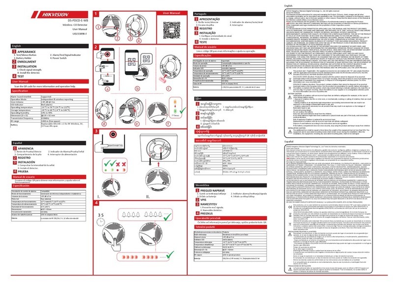
HIK VISION DS-PD2-T10P-WEH1 User manual

The baeries supplied have been chosen to provide long service life whilst,
for safety reasons, having limited output current.
The baery leads must be connected for operaon. When disposing of the
product, the baery must be removed and disposed of separately in
accordance with the local regulaons.
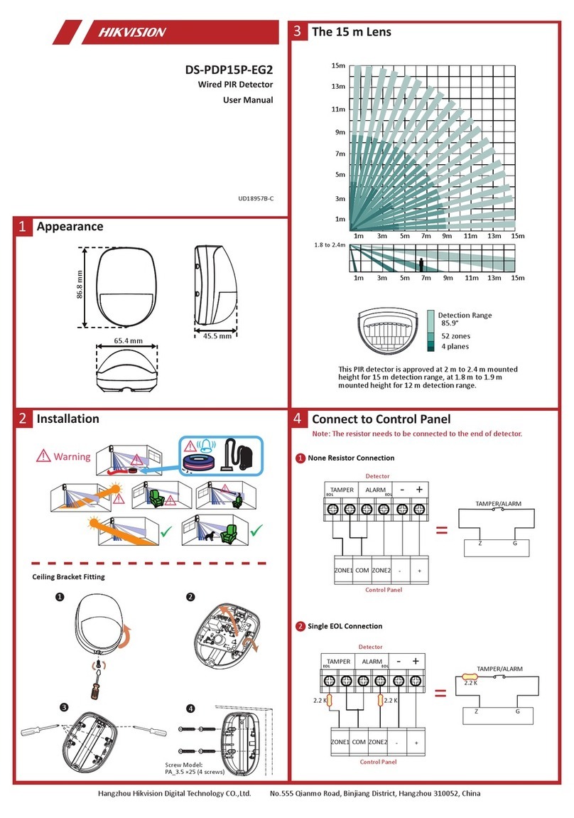
Detectors Technical Characteriscs
Detecon Range
Detecon Angle
Detecon Zones
Detecon Speed
Mounng Height
Two-way Wireless Technology
Blue Wave Technology
Dual Element Pyroelectric Sensor
Tamper Protecon
Intergrated Walk Test Buzzer
Separated LED Indicaon
Signal Strength Indicators (SSI)
3 Microwave Frequencies to Avoid Interference
Digital Independent Floang Threshold(IFT) Technology
Plasc Housing
Animal Immunity
Opcs
Adjustable Sensivity
Lens
Detecon Method
Sensor
Weatherproof
Cerfied Operang Temperature
Physical Dimensions(H x W x D)
Weight
Transmission Frequency
Range in Open Space
Baery Type
Rotatable Wall Mounted
Fixed Wall Mounted
Ceiling Mounted
Baery
10m
90°
78 zones and 5 planes
0.25–3m/s
1.8-2.4m
Yes
Yes
Yes
Front, rear, and bracket tamper signal input
Yes
Top: Microwave, PIR 1 and alarm
Boom: PIR 2
Yes
Yes
Yes
Polycarbonate
10kg
Sealed
High or low range
0.4mm HDPE in lens area
UV compensated
Tri-Signal Detecon Logic
2 low noise dual element passive infrared sensors and a microwave doppler unit
IP55 rated
-25℃~ +60℃(Cerfied)
180mm x 80mm x 105mm
500g
868MHz, FM transceiver
800m
2x3V Lithium baery (included)
Yes – addional wall and fixed brackets available separately
Addional Baery available separately
Electrical & baery
Accessories
EN50131-2-4:2008
EN50131-1:2006+A1:2009
Security Grade (SG)2
Environmental Class(EC)IV
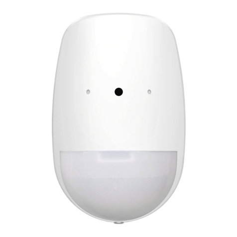
DS-PD2-T10P-WEH/WEH1
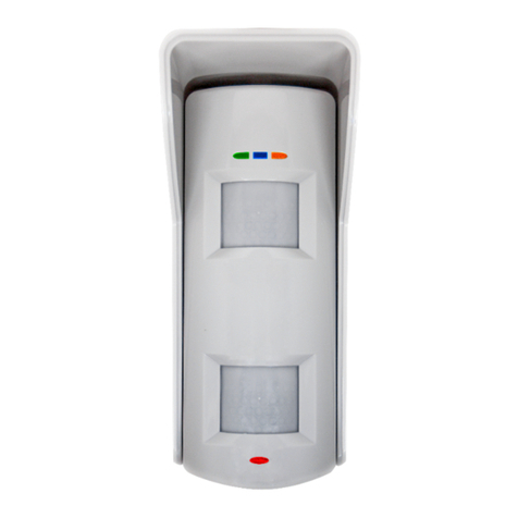
Wireless 10m Pet Immune PIR Detector
12
34
Diagram References
Technical Specification
Baery Informaon
PCB Overview
LED Indications
Microwave Adjustment:0m to 15m
Dip Switched 1-4
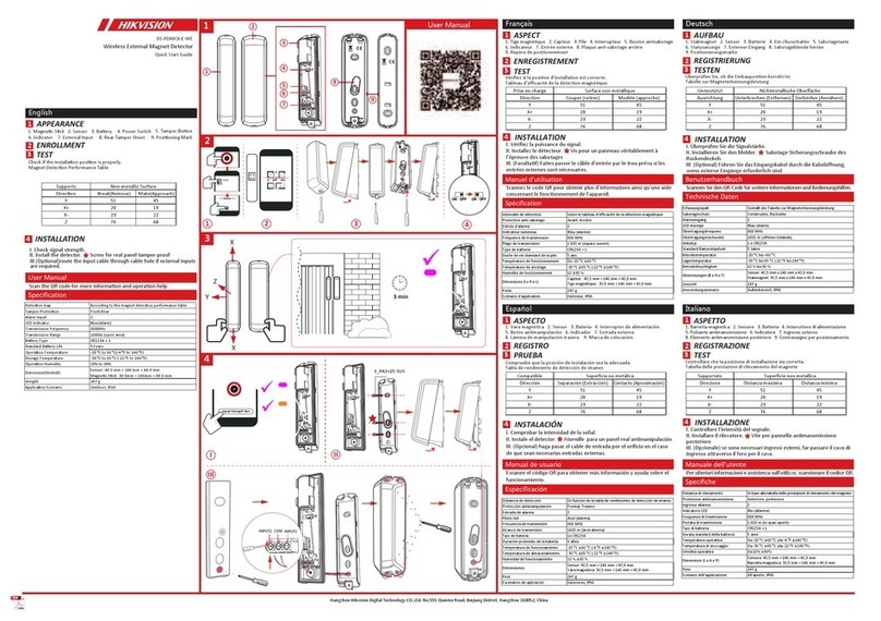
Registration
Please register the device within 90 seconds aer it being powered on.
Register Locally
1. Make the security control panel enter the registraon mode.
2. Register the detector: Hold the registraon key unl the three LEDs flash
alternately. The green LED will flash 8 mes if the registraon is finished.
3. Communicaon Test: Release the TEMPER spring to trigger the alarm.
Note: The distance between the security control panel and the detector
should be less than 50 cm.
Initialize the Detector
1. Remove the baery to power the detector off.
2. 5s later, hold the registraon key and reinstall the baery to power the
detector on at the same me to make the three LEDs start flashing alternately.
Release the registraon key while the three LEDs flash once together.
Signal Strength Test
Inserting the Fixed Mask or Flexible Mask
Flexible Mask Adjustment(1)
Flexible Mask Adjustment(2)
10m Lens Diagram
Wall Mounting Bracket &Adapter
Wall Mounting Bracket
Fixed Bracket
Guidelines
1
4
3
11 12
11 12
13
5
2
3
4
5
6
7
8
9
10
12
11
13
14
ENGLISH
Environmental and Operang Features
965
7
8
10
11
User Manual
COPYRIGHT © 2018 Hangzhou Hikvision Digital Technology Co., Ltd.
ALL RIGHTS RESERVED.
Any and all informaon, including, among others, wordings, pictures, graphs are the properes of
Hangzhou Hikvision Digital Technology Co., Ltd. or its subsidiaries (hereinaer referred to
be “Hikvision”).
This user manual (hereinaer referred to be “the Manual”) cannot be reproduced,changed,
translated, or distributed, parslly or wholly, by any means, without the prior wrien permission
of Hikvision.
Unless otherwise spulated, Hikvision does not make any warranes, guarantees or
representaons, express or implied, regarding to the Manual.
About this Manual
This manual is applicable to detector.
The Manual includes instrucons for using and managing the product. Pictures, charts, images
and all other informaon hereinaer are for descripon and explanaon only. The informaon
contained in the
Manual is subject to change, without noce, due to firmware updates or other reasons.
Please find the latest version in the company website (hp://overseas.hikvision.com/en/).
Please use this user manual under the guidance of professionals.
Trademarks Acknowledgement
and other Hikvision’s trademarks and logos are the properes of Hikvision in various
jurisdicons. Other trademarks and logos menoned below are the properes of their
respecve owners.
This product and - if applicable - the supplied accessories too are marked
with“CE”and comply therefore with the applicable harmonized European
standards listed under the RE Direcve 2014/53/EU, the RoHS Direcve
2011/65/EU.
For electrical products sold within the European Community. At the end
of the electrical products life,it should not be disposed of with household
waste. Please recycle where facilies exist. Check with your local Authority
or retailer for recycling advice in your country.
This product operates in a
European non-harmonised
frequency band
12 13
14
Product Information
FRANÇAIS
ESPAÑOL
P O RTUGUÊS
I T A L IANO
Références du schéma
Vue d'ensemble du PCB
LED indicatrices
Ajustement des micro-ondes: 0à15m
Microcommutateurs1-4
Inscription
Test de force du signal
Insérer un masque fixe ou flexible
Ajustement du masque flexible (1)
Ajustement du masque flexible (2)
Schéma de l'objectif 10m
Support de montage mural et adaptateur
Support de montage mural
Support fixe
Directives
1
2
33
34
35
1
2
3
4
5
3
6
38
39
3
314
6
7
8
9
10
11
13
314
14
314
12
Veuillez inscrire l’appareil dans un délai de 90 secondes
après sa mise en route.
Inscription locale
1. Accéder au mode inscripon sur le panneau de
commande de sécurité.
2. Inscripon du détecteur : Maintenez enfoncée la
touche d’inscripon jusqu’à ce que les trois voyants
clignotent en alternance. Le voyant vert clignotera 8
fois si l’inscripon est terminée.
3. Test de communicaon : Relâchez le ressort an-sabotage pour déclencher l’alarme.
Remarque : La distance entre le panneau de commande sécurité et le détecteur doit être inférieure à 50 cm.
Initialisation du détecteur
1. Rerez la baerie pour éteindre le détecteur.
2. 5 secondes plus tard, maintenez enfoncée la touche d’inscripon et réinstallez la baerie pour mere en route
le détecteur en même temps pour que les trois voyants commencent à clignoter en alternance. Relâchez la
touche d’inscripon pendant que les trois voyants clignotent une fois ensemble.
Français
4
DEL désacvé
Buzzer désacvé
PIR supérieur
BASSE
PIR inférieur
BASSE
Voyants allumés
Buzzer acvé
PIR supérieur
HAUTE
PIR inférieur
HAUTE
ACTIVERDÉSACTIVÉ
ACTIVER
Spécifications techniques
Caractérisques techniques du détecteur
Portée de détecon : 10 m
Angle de détecon : 90°
Zones de détecon : 78 zones et 5 plans
Vitesse de détecon : 0,25-3 m/s
Hauteur de fixaon : 1,8-2,4 m
Technologie bidireconnelle sans fil
Technologie Blue Wave
Capteur pyroélectrique à deux éléments
Protecon an-sabotage Entrée du signal ansabotage avant, arrière et support
Aversseur de test de fonconnement intégré
Indicaon lumineuse séparée Pare supérieure : Micro-ondes, PIR 1 et alarme | Pare inférieure : PIR 2
Indicateurs de puissance du signal (SSI)
3 fréquences micro-ondes pour éviter les interférences
Technologie à seuils floants indépendants numériques (IFT)
Boîer en plasque : Polycarbonate
Immunité aux animaux : 10 kg
Opques : Scellées
Sensibilité réglable : Plage élevée ou basse ; HDPE de 0,4 mm dans la zone de l’objecf
Lenlle : UV compensé
Méthode de détecon : Logique de détecon à trois signaux
Capteur : 2 capteurs infrarouges passifs à deux éléments faible bruit et 1 capteur Doppler à
micro-ondes
Caractérisques environnementales et de fonconnement
Résistant aux intempéries : Classé IP55
Température de fonconnement cerfiée : -25 °C à +60 °C (cerfiée)
Dimensions physiques (H x L x P) : 180 mm x 80 mm x 105 mm
Poids : 500 g
Caractérisques électriques et baerie
Fréquence de transmission : Émeeur-récepteur FM (868 MHz)
Portée en espace dégagé : 800 m
Type de baerie : 2 baeries au lithium de 3 V (incluses)
Accessoires
Supports fixes et muraux supplémentaires disponibles séparément
Piles : Baerie supplémentaire disponible séparément
PIR SUPÉRIEUR ALARME MICRO-ONDES
PIR INFÉRIEUR
Mise sous tension
Baerie faible
PIR supérieur acvé
Micro-ondes acvées
Alarme
PIR inférieur acvé
Referências do diagrama
Visão geral da PCB
Indicações dos LEDs
Ajuste do micro-ondas: 0 a 15 m
Chaves DIP Switch 1-4
Registro
Teste de intensidade do sinal
Inserir a máscara fixa ou a máscara flexível
Ajuste da máscara flexível (1)
Ajuste da máscara flexível (2)
Diagrama da lente de 10 m
Suporte e adaptador para montagem na parede
Suporte para montagem na parede
Suporte fixo
Instruções
1
2
33
34
35
1
2
3
4
5
3
6
38
39
3
314
6
7
8
9
10
11
13
314
14
314
12
Registre o disposivo dentro de 90 segundos depois de
ele ser ligado.
Registrar localmente
1. Coloque o painel de controle de segurança no modo
de registro.
2. Registre o detector: mantenha pressionada a tecla
de registro até que os três LEDs pisquem
alternadamente. O LED verde piscará 8 vezes quando
o registro for concluído.
3. Teste de comunicação: solte a mola de VIOLAÇÃO para acionar o alarme.
Observação: a distância entre o painel de controle de segurança e o detector deve ser menor do que 50 cm.
Inicializar o detector
1. Remova a bateria para desligar o detector.
2. Cinco segundos depois, mantenha pressionada a tecla de registro e, ao mesmo tempo, reinstale a bateria para
ligar o detector, o que fará com que os três LEDs comecem a piscar alternadamente. Solte a tecla de registro
quando os três LEDs piscarem juntos ao mesmo tempo.
Português
4
LEDs DESLIGADOS
Campainha DESLIGADA
PIR superior
BAIXO
PIR inferior
BAIXO
LEDs LIGADOS
Campainha LIGADA
PIR superior
ALTO
PIR inferior
ALTO
LIGADODESLIGADO
LIGADO
Especificação técnica
Caracteríscas técnicas do detector
Faixa de detecção: 10 m
Ângulo de detecção: 90°
Zonas de detecção: 78 zonas e 5 planos
Velocidade de detecção: 0,25 a 3 m/s
Altura de montagem: 1,8 a 2,4 m
Tecnologia bidirecional sem fio
Tecnologia Blue Wave
Sensor piroelétrico de elemento duplo
Proteção anviolação: entrada de sinal de violação frontal, traseira e do suporte
Campainha integrada de teste de caminhada
Indicações de LED separadas: superior: micro-ondas, PIR 1 e alarme; inferior: PIR 2
Indicadores de intensidade de sinal (SSI)
Três frequências de micro-ondas para evitar interferências
Tecnologia de limite flutuante independente (IFT) digital
Invólucro plásco: policarbonato
Imunidade a animais: 10 kg
Ópca: selado
Sensibilidade ajustável: faixa maior ou menor; HDPE de 0,4 mm na área da lente
Lente: compensação UV
Método de detecção: lógica de detecção de três sinais
Sensor: dois sensores infravermelhos passivos de duplo elemento e baixo ruído e uma unidade
doppler de micro-ondas
Caracteríscas ambientais e operacionais
Exposição ao tempo: classificação IP55
Temperatura cerficada de operação: -25 °C a +60 °C (cerficado)
Dimensões sicas (A x L x P): 180 mm x 80 mm x 105 mm
Peso: 500 g
Componentes elétricos e bateria
Frequência de transmissão: 868 MHz, transmissor de FM
Alcance em espaço aberto: 800 m
Tipo de bateria: 2 x baterias de 3 V de lío (incluídas)
Acessórios
Suportes adicionais de parede e fixo disponíveis separadamente
Bateria: bateria adicional disponível separadamente
PIR SUPERIOR ALARME MICRO-ONDAS
PIR INFERIOR
Ligando
Bateria fraca
PIR superior avado
Micro-ondas avado
Alarme
PIR inferior avado
Referencias del diagrama
Vista del PCB
Indicaciones led
Ajuste de microondas: 0 m a 15 m
Interruptor DIP 1-4
Registro
Prueba de intensidad de señal
Introducir la máscara fija o flexible
Ajustes de máscara flexible (1)
Ajustes de máscara flexible (2)
Diagrama de las lentes de 10 m
Soporte de montaje en pared y adaptador
Soporte de montaje en pared
Soporte fijado
Pautas
1
2
33
34
35
1
2
3
4
5
3
6
38
39
3
314
6
7
8
9
10
11
13
314
14
314
12
Registre el disposivo en un periodo de 90 segundos
después de encenderlo.
Registrar localmente
1. Asegúrese de que el panel de control de seguridad
acceda al modo de registro.
2. Registro del detector: Mantenga pulsado el botón de
registro hasta que los tres ledes parpadeen
alternavamente. El led verde parpadeará 8 veces
una vez finalizado el registro.
3. Prueba de comunicación: Suelte el muelle de MANIPULACIÓN para disparar la alarma.
Nota: La distancia entre el panel de control de seguridad y el detector debe ser menor de 50 cm.
Inicializar el detector
1. Rere la pila para apagar el detector.
2. 5 s después, mantenga pulsado el botón de registro y vuelva a insertar la pila para encender el detector al
mismo empo para que los tres ledes empiecen a parpadear alternavamente. Suelte el botón de registro
cuando los tres LED parpadeen a la vez.
Inglés
4
LEDES APAGADOS
Timbre APAGADO
PIR superior
BAJO
PIR inferior
BAJO
LEDES ENCENCIDOS
Timbre ENCENDIDO
PIR superior
ALTO
PIR inferior
ALTO
ENCENDIDODESACTIVADO
ENCENDIDO
Especificaciones técnicas
Caracteríscas técnicas de los detectores
Campo de detección: 10 m
Ángulo de detección: 90°
Zonas de detección: 78 zonas y 5 planos
Velocidad de detección: 0,25-3 m/s
Altura de montaje: 1,8-2,4 m
Tecnología inalámbrica bidireccional
Tecnología Blue Wave
Sensor piroeléctrico de elemento dual
Protección contra manipulación: Frontal, trasera y entrada de señal de manipulación de soporte
Timbre de prueba integrado
Indicación led separada: Superior: Microondas, PIR 1 y alarma; Inferior: PIR 2
Indicadores de fuerza de señal (SSI, de sus siglas en inglés)
3 frecuencias de microondas para evitar interferencias
Tecnología digital de límite flotante independiente (IFT)
Carcasa de plásco: Policarbonato
Inmunidad contra mascotas: 10 kg
Ópca: Sellada
Sensibilidad ajustable: Alcance alto o bajo; HDPE de 0,4 mm en el área de la lente
Lentes: Compensación UV
Método de detección: Lógica de detección de señal triple
Sensor: 2 sensores infrarrojos pasivos de doble elemento y bajo ruido y una unidad Doppler microondas
Caracteríscas ambientales y de funcionamiento
Impermeabilidad: Calificación IP55
Temperatura de funcionamiento cerficada: -25 °C a +60 °C (cerficado)
Dimensiones sicas (alto x ancho x profundidad): 180 mm × 80 mm × 105 mm
Peso: 500 g
Electricidad y pila
Frecuencia de transmisión: 868 MHz, transmisor FM
Alcance en espacios abiertos: 800 m
Tipo de batería: 2 pilas de lio de 3 V (incluidas):
Accesorios
Soportes de pared y fijos adicionales disponibles por separado
Batería: Pila adicional disponible por separado
PIR superior ALARMA MICROONDAS
PIR inferior
Encendido
Batería baja
PIR superior acvado
Microondas acvado
Alarma
PIR inferior acvado
Riferimento schemi
Panoramica PCB
LED
Regolazione microonde: da 0 a 15 m
Microinterruttori 1-4
Registrazione
Test di potenza del segnale
Inserimento della maschera fissa o flessibile
Regolamento della maschera flessibile (1)
Regolamento della maschera flessibile (2)
Diagramma obiettivo 10 m
Staffa di montaggio a parete e adattatore
Staffa di montaggio a parete
Staffa fissa
Linee guida
1
2
33
34
35
1
2
3
4
5
3
6
38
39
3
314
6
7
8
9
10
11
13
314
14
314
12
Registrare il disposivo entro 90 secondi dopo
l'accensione.
Registrazione locale
1. Entrare in modalità di registrazione del pannello di
controllo di sicurezza.
2. Registrazione del rilevatore: tenere premuto il tasto
di registrazione fino a che i tre LED non lampeggiano
alternavamente. Il LED verde lampeggia 8 volte al
termine della registrazione.
3. Test di comunicazione: rilasciare la molla MANOMISSIONE per avare l'allarme.
Nota: la distanza tra il pannello di controllo di sicurezza e il rilevatore deve essere meno di 50 cm.
Inizializzazione del rilevatore
1. Rimuovere la baeria per spegnere il rilevatore.
2. Dopo 5 secondi, premere il tasto di registrazione e reinstallare la baeria allo stesso tempo per accendere il
rilevatore e far lampeggiare alternavamente i tre LED. Rilasciare il tasto di registrazione mentre i tre LED
lampeggiano insieme una volta.
Italiano
4
LED DISATTIVO
Cicalino DISATTIVO
PIR superiore
BASSO
PIR inferiore
BASSO
LED ATTIVO
Cicalino ATTIVO
PIR superiore
ALTO
PIR inferiore
ALTO
ATTIVODISATTIVO
ATTIVO
Specifiche tecniche
Caraerische tecniche del rilevatore
Area di copertura: 10 m
Angolo di rilevamento: 90°
Zone di rilevamento: 78 zone e 5 piani
Velocità di rilevamento: 0,25-3 m/s
Altezza di montaggio: 1,8-2,4 m
Tecnologia wireless bidirezionale
Tecnologia Blue Wave
Sensore piroelerico a due elemen
Protezione da manomissioni: ingresso segnale di manomissione anteriore, posteriore e staffa
Suoneria di walk test integrata
Indicatori LED disn: Parte superiore: microonde, PIR 1 e allarme; inferiore: PIR 2
Indicatore potenza segnale (SSI)
3 frequenze a microonde per evitare interferenze
Tecnologia IFT (Soglia variabile digitale indipendente)
Custodia di plasca: policarbonato
Immunità agli animali: 10 kg
Componen oci: sigilla
Sensibilità regolabile: Intervalli eleva o bassi: 0,4 mm HDPE nell'area dell'obievo
Obievo: con compensazione UV
Metodo di rilevazione: logica di rilevamento a tre segnali
Sensore: 2 sensori agli infrarossi passivi a doppio elemento e basso rumore e un'unità doppler a
microonde
Funzionalità operave e ambientali
Resistenza agen atmosferici: cerficato livello IP55
Temperatura di esercizio cerficata: da -25 °C a +60 °C (cerficata)
Dimensioni fisiche (A x L x P): 180 mm x 80 mm x 105 mm
Peso: 500 g
Elericità e baeria
Frequenza di trasmissione: 868 MHz, ricetrasmetore FM
Portata in spazi aper: 800 m
Tipo di baeria: 2 baerie al lio da 3 V (incluse)
Accessori
Staffe da parete o fisse supplementari disponibili a parte
Baeria: baeria supplementare disponibile a parte
PIR SUPERIORE ALLARME MICROONDE
PIR INFERIORE
Accensione
Baeria scarica
PIR superiore avato
Microonde avato
Allarme
PIR inferiore avato
Р У ССКИЙ
Ссылки на рисунки
Обзор печатной платы
Светодиодная индикация
Регулировка микроволнового датчика: от 0 до 15м
DIP-переключатель: 1-4
Регистрация
Проверка уровня сигнала
Вставка фиксированной или гибкой маски
Регулировка гибкой маски (1)
Регулировка гибкой маски (2)
Схема объективов, диапазон 10м
Кронштейн для настенного монтажа и адаптер
Кронштейн для настенного монтажа
Фиксированный кронштейн
Рекомендации
1
2
33
34
35
1
2
3
4
5
3
6
38
39
3
314
6
7
8
9
10
11
13
314
14
314
12
Зарегистрируйте устройство в течение 90 секунд после
включения питания.
Локальная регистрация
1. Включите режим регистрации на панели управления
системой безопасности.
2. Регистрация датчика: Нажмите и удерживайте
кнопку регистрации, пока три светодиода не начнут
мигать поочередно. Когда регистрация будет
выполнена, зеленый светодиод мигнет 8 раз.
3. Тестирование связи: Отпустите пружину датчика ВЗЛОМА для активации сигнала тревоги.
Примечание. Расстояние между панелью управления системой безопасности и датчиком должно быть
менее 50 см.
Инициализация датчика
1. Извлеките батарею для выключения датчика.
2. Через 5 секунд нажмите кнопку регистрации и, удерживая ее, вставьте снова батарею. После этого три
светодиода начнут мигать поочередно. Отпустите кнопку регистрации, когда все три светодиода мигнут
один раз одновременно.
Русский
4
Светодиодная индикация
ВЫКЛ.
Зуммер ВЫКЛ.
Верхний пассивный ИК-датчик
НИЗКАЯ
Нижний пассивный ИК-датчик
НИЗКАЯ
Светодиодная индикация
ВКЛ.
Зуммер ВКЛ.
Верхний пассивный ИК-датчик
ВЫСОКАЯ
Нижний пассивный ИК-датчик
ВЫСОКАЯ
ВКЛ.ВЫКЛ.
ВКЛ.
Технические характеристики
Технические характеристики датчиков
Диапазон обнаружения: 10 м
Угол обнаружения: 90°
Зоны обнаружения: 78 зон и 5 плоскостей
Скорость обнаружения: 0,25–3 м/с
Монтажная высота: 1,8–2,4 м
Двунаправленная беспроводная технология
Технология Blue Wave
Двойной элемент пироэлектрического датчика
Защита от взлома: вход сигнала датчиков взлома (переднего, заднего и кронштейна)
Встроенный зуммер теста ходьбой
Отдельные светодиоды: Верх: микроволновый датчик, пассивный ИК-датчик 1, сигнал тревоги;
низ: пассивный ИК-датчик 2
Индикаторы уровня сигнала (SSI)
3 частоты микроволнового излучения для предотвращения помех
Технология цифровых независимых плавающих порогов
Пластиковый корпус: поликарбонат
Отсутствие ложных срабатываний при обнаружении домашних животных: 10 кг
Оптика: герметичная
Регулируемая чувствительность: Высокий/низкий диапазон; 0,4 мм HDPE в области объектива
Линза: компенсация ультрафиолетового излучения
Способ обнаружения: логика распознавания тройным сигналом
Датчик: 2 малошумных пассивных инфракрасных датчика с двойным элементом и
микроволновый доплеровский датчик
Эксплуатационные характеристики и характеристики среды
Защита от погодных условий: уровень защиты IP55
Сертифицированная рабочая температура: от -25 до +60 °C (сертифицировано)
Физические размеры (В x Ш x Г): 180 мм x 80 мм x 105 мм
Масса: 500 г
Электропитание и батарея
Частота передачи: 868 МГц, FM
Дальность действия на открытом пространстве: 800 м
Тип батареи: 2 литиевые батареи, 3 В (прилагаются)
Вспомогательное оборудование
Дополнительные настенные и фиксированные кронштейны поставляются отдельно
Батарея: Дополнительную батарею можно приобрести отдельно
ВЕРХНИЙ ПАССИВНЫЙ
ИК-ДАТЧИК
ТРЕВОГА МИКРОВОЛНОВЫЙ
ДАТЧИК
НИЖНИЙ ПАССИВНЫЙ
ИК-ДАТЧИК
Включение питания
Батарея разряжена
Активирован верхний
пассивный ИК-датчик
Активирован
микроволновый датчик
Сигнал тревоги
Активирован нижний
пассивный ИК-датчик
Deutsch
Schaubilder
PCB-Überblick
LED-Anzeigen
Mikrowelleneinstellung: 0 m bis 15 m
DIP-Schalter 1 – 4
Registrierung
Signalstärketest
Starre oder flexible Maske einsetzen
Flexible Maske einstellen (1)
Flexible Maske einstellen (2)
10 m Objektivdiagramm
Wandhalterung und Netzteil
Wandhalterung
Starre Halterung
Hinweise
1
2
33
34
35
1
2
3
4
5
3
6
38
39
3
314
6
7
8
9
10
11
13
314
14
314
12
Registrieren Sie den Melder innerhalb von 90 Sekunden
nach dem Einschalten.
Lokale Registrierung
1. Rufen Sie an der Alarmzentrale den Registriermodus
auf.
2. Den Melder registrieren: Halten Sie die
Registrierungstaste gedrückt, bis die drei LEDs
abwechselnd blinken. Die grüne LED blinkt 8-mal,
wenn die Registrierung abgeschlossen ist.
3. Kommunikaonstest: Lassen Sie den SABOTAGE-Kontakt los, um den Alarm auszulösen.
Hinweis: Der Abstand zwischen Alarmzentrale und Melder sollte unter 50 cm liegen.
Melder initialisieren
1. Nehmen Sie die Baerie heraus, um den Melder abzuschalten.
2. Halten Sie nach 5 Sekunden die Registrierungstaste gedrückt und setzen Sie die Baerie wieder ein. Damit
wird der Melder gleichzeig wieder eingeschaltet und die drei LEDs blinken abwechselnd. Lassen Sie die
Registrierungstaste los, während die drei LEDs einmal gemeinsam aulinken.
Deutsch
4
LEDs AUS
Summer AUS
PIR oben
NIEDRIG
PIR unten
NIEDRIG
LEDs EIN
Summer EIN
PIR oben
HOCH
PIR unten
HOCH
EINAUS
Technische Daten
Melder technische Daten
Erkennungsbereich: 10 m
Erkennungswinkel: 90°
Erkennungsbereiche: 78 Zonen and 5 Ebenen
Erfassungsgeschwindigkeit: 0,25 – 3 m/s
Befesgungshöhe: 1,8 – 2,4 m
Zweiwege-Drahtlostechnologie
Blue-Wave-Technik
Pyroelektrischer Dual-Element-Sensor
Sabotageschutz: Eingang für das Sabotagesignal vorne, hinten und an der Halterung
Integrierter Gehtest-Summer
Getrennte LED-Anzeige: Oben: Mikrowelle, PIR 1 und Alarm; unten: PIR 2
Signalstärkeanzeigen (SSI)
3 Mikrowellenfrequenzen zur Vermeidung von Störungen
Digitale unabhängige Fließende-Schwellen-Technologie („Floang Threshold“, IFT)
Kunststoffgehäuse: Polycarbonat
Unempfindlichkeit gegen Tiere: 10 kg
Opk: Versiegelt
Einstellbare Empfindlichkeit: Hoher oder niedriger Bereich; 0,4 mm HDPE-Objekvbereich
Objekv: UV-kompensiert
Erkennungsmethode: Drei-Signal-Erkennungslogik
Sensor: 2 rauscharme Dual-Element-Passiv-Infrarot-Melder und eine Mikrowellen-Doppler-Einheit
Umwelt- und Betriebsmerkmale
Weerfest: Schutzart IP55
Zerfizierte Betriebstemperatur: -25 °C bis +60 °C (zerfiziert)
Abmessungen (H x B x T): 180 mm x 80 mm x 105 mm
Gewicht: 500 g
Elektrische Spezifikaonen und Baerie
Übertragungsfrequenz: 868 MHz, UKW-Transceiver
Reichweite im freien Gelände: 800 m
Baerietyp: 2 x 3-V-Lithium-Baerie (mitgeliefert)
Zubehör
Zusätzliche Wand- und starre Halterungen separat erhältlich
Baerie: Zusätzliche Baerie separat erhältlich
PIR OBEN ALARM MIKROWELLE
PIR UNTEN
Hochfahren
Baerie schwach
PIR oben akviert
Mikrowelle akviert
Alarm/Alarme
PIR unten akviert
Polski
Opis diagramu
Wygląd PCB
Wskaźniki LED
Regulacja mikrofal: 0 m do 15 m
Przełącznik DIP 1-4
Rejestracja
Test siły sygnału
Ustawienie sztywnej lub elastycznej wartości maski
Regulacja elastycznej wartości maski (1)
Regulacja elastycznej wartości maski (2)
Ilustracja przedstawiająca obiektyw 10 m
Zaczep do montażu na ścianie i zasilacz
Zaczep do montażu na ścianie
Stały zaczep
Wskazówki
1
2
33
34
35
1
2
3
4
5
3
6
38
39
3
314
6
7
8
9
10
11
13
314
14
314
12
Zarejestruj urządzenie do 90 sekund od jego włączenia.
Rejestrowanie lokalnie
1. Przełącz centralę alarmową do trybu rejestracji.
2. Zarejestruj detektor: Naciśnij i przytrzymaj przycisk
rejestracji do chwili, gdy trzy wskaźniki zaczną migać
na przemian. Zielony wskaźnik zamiga 8 razy po
zakończeniu rejestracji.
3. Test komunikacji: Zwolnij sprężynę TAMPER, aby
aktywować alarm.
Uwaga: Odległość centrali alarmowej od detektora powinna być mniejsza niż 50 cm.
Inicjowanie detektora
1. Wyjmij baterię, aby wyłączyć zasilanie detektora.
2. Po upływie 5 sekund naciśnij i przytrzymaj przycisk rejestracji, ponownie zainstaluj baterię, aby włączyć
zasilanie detektora, i upewnij się, że trzy wskaźniki zaczną migać na przemian. Zwolnij przycisk rejestracji, gdy
trzy wskaźniki migną równocześnie.
Polski
4
WYŁ. LED-y
WYŁ. brzęczyk
GÓRNY CZUJNIK
PIR NISK.
Dolny czujnik
PIR NISK.
WŁ. LED-y
WŁ. brzęczyk
GÓRNY CZUJNIK
PIR WYS.
Dolny czujnik
PIR WYS.
WŁ.WYŁ.
Specyfikacje techniczne
Specyfikacja techniczna czujników
Zasięg detekcji: 10 m
Kąt detekcji: 90°
Strefy detekcji: 78 stref i 5 płaszczyzn
Szybkość detekcji: 0,25–3 m/s
Wysokość montażu: 1,8–2,4 m
Dwukierunkowa komunikacja bezprzewodowa
Technologia Blue Wave
Dwuczęściowy czujnik pyroelektryczny
Zabezpieczenie antysabotażowe: Sygnał wejściowy sabotażu panelu przedniego i tylnego oraz
uchwytu
Zintegrowany brzęczyk testu
Wskaźniki LED: Górny: Mikrofale, PIR 1 i alarm, Dolny: PIR 2
Wskaźniki siły sygnału (SSI)
3 częstotliwości mikrofalowe dla uniknięcia zakłóceń
Technologia Digital Independent Floang Threshold (IFT)
Plaskowa obudowa: Poliwęglan
Niereagowanie na zwierzęta domowe: 10kg
Układ optyczny: Hermetyczny
Regulacja czułości: Mniejszy lub większy zasięg; 0,4 mm HDPE w obszarze pokrytym przez obiektyw
Obiektyw: Kompensacja UV
Metoda detekcji: Algorytm detekcji Tri-Signal
Czujnik: Dwa niskoszumowe dwuelementowe pasywne czujniki podczerwieni i mikrofalowy czujnik
Dopplera
Informacje środowiskowe i działania
Odporność na warunki atmosferyczne: Stopień ochrony IP55
Certyfikowany zakres temperatur działania: -25°C ~ +60°C (certyfikacja)
Wymiary (W x S x G): 180 mm x 80 mm x 105 mm
Waga: 500g
Zasilanie elektryczne i baterie
Częstotliwość transmisji: 868 MHz, nadajnik-odbiornik FM
Zasięg na otwartej przestrzeni: 800 m
Typ baterii: 2x3V baterie litowe (w zestawie)
Akcesoria
Dodatkowe zaczepy do montażu na ścianie i stałe dostępne oddzielnie
Bateria: Dodatkowe baterie dostępne oddzielnie
GÓRNY CZUJNIK PIR ALARM MIKROFALE
DOLNY CZUJNIK PIR
Włączanie zasilania
Niski poziom baterii
Aktywowano górny czujnik PIR
Aktywowane mikrofalami
Alarm/Allarme
WŁĄCZONO DOLNY CZUJNIK PIR

This manual suits for next models

1

Other HIK VISION Security Sensor manuals

HIK VISION DS-PDP18-HM-WE User manual

HIK VISION

HIK VISION DS-PDP18-HM-WE User manual

HIK VISION DS-PDD12P-EG2-WB User manual

HIK VISION

HIK VISION DS-PDD12P-EG2-WB User manual

HIK VISION DS-PDMCK-EG2-WB User manual

HIK VISION

HIK VISION DS-PDMCK-EG2-WB User manual

HIK VISION DS-PDBG8-EG2-WB User manual

HIK VISION

HIK VISION DS-PDBG8-EG2-WB User manual

HIK VISION DS-PDPG12P-EG2-WE User manual

HIK VISION

HIK VISION DS-PDPG12P-EG2-WE User manual

HIK VISION DS-PDMCX-E-WE User manual

HIK VISION

HIK VISION DS-PDMCX-E-WE User manual

HIK VISION Door Station User manual

HIK VISION

HIK VISION Door Station User manual

HIK VISION DS-PDBG8-EG2 User manual

HIK VISION

HIK VISION DS-PDBG8-EG2 User manual

HIK VISION DS-PDC10AM-EG2-WB User manual

HIK VISION

HIK VISION DS-PDC10AM-EG2-WB User manual

HIK VISION DS-PDPC12P-EG2-WE User manual

HIK VISION

HIK VISION DS-PDPC12P-EG2-WE User manual

HIK VISION DS-TDSB00-EKT/POE/4M User manual

HIK VISION

HIK VISION DS-TDSB00-EKT/POE/4M User manual

HIK VISION DS-PDP18-EG2 User manual

HIK VISION

HIK VISION DS-PDP18-EG2 User manual

HIK VISION DS-PDPG8P-EG2-WE User manual

HIK VISION

HIK VISION DS-PDPG8P-EG2-WE User manual

HIK VISION TurboHD DS-2CE11D8T-PERL User manual

HIK VISION

HIK VISION TurboHD DS-2CE11D8T-PERL User manual

HIK VISION AX PRO DS-PDPC12P-EG2-WE User manual

HIK VISION

HIK VISION AX PRO DS-PDPC12P-EG2-WE User manual

HIK VISION DS-PD2-T10P-WEH User manual

HIK VISION

HIK VISION DS-PD2-T10P-WEH User manual

HIK VISION DS-PDC10AM-EG2-WE User manual

HIK VISION

HIK VISION DS-PDC10AM-EG2-WE User manual

HIK VISION DS-PDC10DM-EG2-WE User manual

HIK VISION

HIK VISION DS-PDC10DM-EG2-WE User manual

HIK VISION DS-PD2-P15C-W User manual

HIK VISION

HIK VISION DS-PD2-P15C-W User manual

HIK VISION DS-PDP15P-EG2-WE User manual

HIK VISION

HIK VISION DS-PDP15P-EG2-WE User manual

HIK VISION DS-PDC10DM-EG2-WB User manual

HIK VISION

HIK VISION DS-PDC10DM-EG2-WB User manual

HIK VISION Pyronix KX15DQ User manual

HIK VISION

HIK VISION Pyronix KX15DQ User manual

HIK VISION DS-PDWL-E-WB User manual

HIK VISION

HIK VISION DS-PDWL-E-WB User manual

HIK VISION DS-PDC15-EG2-WE User manual

HIK VISION

HIK VISION DS-PDC15-EG2-WE User manual

Popular Security Sensor manuals by other brands

Lince ZENITH GOLD 869 Series Installation, operation and maintenance manual

Lince

Lince ZENITH GOLD 869 Series Installation, operation and maintenance manual

ITE ITE-XTRA manual

ITE

ITE ITE-XTRA manual

pdlux PD-PIR101-Z instruction manual

pdlux

pdlux PD-PIR101-Z instruction manual

Artika Sentinel instruction manual

Artika

Artika Sentinel instruction manual

ADEMCO 5850 installation instructions

ADEMCO

ADEMCO 5850 installation instructions

Mini Gadgets CDB200 user manual

Mini Gadgets

Mini Gadgets CDB200 user manual

klemko IB-06L Installation and operating instructions

klemko

klemko IB-06L Installation and operating instructions

Mobeye CM4300 user manual

Mobeye

Mobeye CM4300 user manual

Leuze MLD 300 operating instructions

Leuze

Leuze MLD 300 operating instructions

AVIRE MEMCO Pana40 Plus installation guide

AVIRE

AVIRE MEMCO Pana40 Plus installation guide

DSC PG9975 installation instructions

DSC

DSC PG9975 installation instructions

Nivel System CLS-1 operating instructions

Nivel System

Nivel System CLS-1 operating instructions

Zennio WinDoor RF Technical documentation

Zennio

Zennio WinDoor RF Technical documentation

Omron G9SX Series Brochure & specs

Omron

Omron G9SX Series Brochure & specs

Vaisala PWD22/52 user guide

Vaisala

Vaisala PWD22/52 user guide

Center 380 instruction manual

Center

Center 380 instruction manual

Balluff BTL7-A/C/E/G5 M HB/WB-KA K Series user guide

Balluff

Balluff BTL7-A/C/E/G5 M HB/WB-KA K Series user guide

Philips Dynalite DUS704W installation manual

Philips

Philips Dynalite DUS704W installation manual

manuals.online logo
manuals.online logoBrands
  • About & Mission
  • Contact us
  • Privacy Policy
  • Terms and Conditions

Copyright 2025 Manuals.Online. All Rights Reserved.