Hilti PR 15 User manual

PR 15
Mode d’emploi 2-43
Operating instructions 44-85
Manual de Instrucciones 86-127

44
PR 15 operating instructions
Symbols used
The symbols used in these operating instructions
have the following meanings:
WARNING
Usage risk or improper use which can cause severe
personal injury or a fatal accident.
Usage information which helps the user to employ
the instrument efficiently and in a technically correct
manner.
Besides the instructions for use, these operating
instructions also contain important safety notes
(see «Safety instructions» section)
Please read through these operating instructions
carefully before using the tool.
Contents

45
Contents
1. Product information . . . . . . . . . . . . . . . . . . . . . . . . . . . . . . . 46
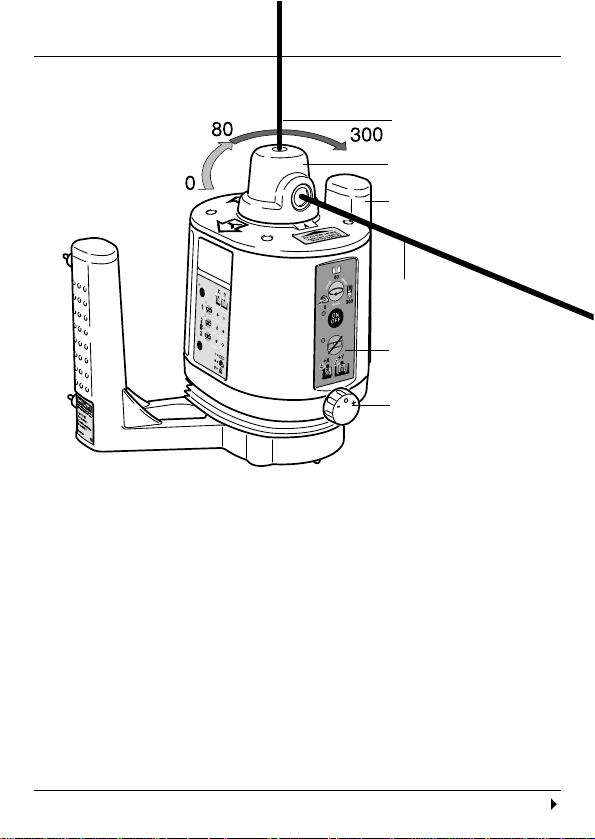
Functional description . . . . . . . . . . . . . . . . . . . . . . .46
Operating controls and indicators . . . . . . . . . . . . . .49
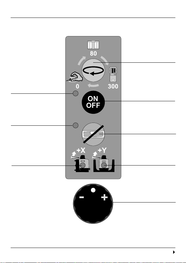
Control panel . . . . . . . . . . . . . . . . . . . . . . . . . . . . .50
Quick-start instructions . . . . . . . . . . . . . . . . . . . . . .53
Technical data . . . . . . . . . . . . . . . . . . . . . . . . . . . . .54
Items supplied . . . . . . . . . . . . . . . . . . . . . . . . . . . .57
Beam catcher . . . . . . . . . . . . . . . . . . . . . . . . . . . . .58
2. Safety instructions . . . . . . . . . . . . . . . . . . . . . . . . . . . . . . . . 59
Please read this now! . . . . . . . . . . . . . . . . . . . . . . .59
Laser classification . . . . . . . . . . . . . . . . . . . . . . . . .59
Applications for which the tool is designed . . . . . . .60
Electromagnetic compatibility (EMC) . . . . . . . . . . .60
Usage and handling . . . . . . . . . . . . . . . . . . . . . . . .61
3. Initial operation and usage . . . . . . . . . . . . . . . . . . . . . . . . . 63
Inserting the batteries . . . . . . . . . . . . . . . . . . . . . . .63
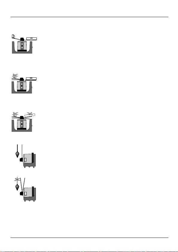
Horizontal mode . . . . . . . . . . . . . . . . . . . . . . . . . . .64
Vertical mode . . . . . . . . . . . . . . . . . . . . . . . . . . . . .65
Inclined plane mode . . . . . . . . . . . . . . . . . . . . . . . .66
Operation with the beam catcher (1-30 m) . . . . . . .67
Operation with the manual detector (1-100 m) . . . .68
4. Checks. . . . . . . . . . . . . . . . . . . . . . . . . . . . . . . . . . . . . . . . . . 69
Checking horizontal rotation . . . . . . . . . . . . . . . . . .69
Checking vertical rotation . . . . . . . . . . . . . . . . . . . .72
Making adjustments . . . . . . . . . . . . . . . . . . . . . . . .73
Checking the oblique error . . . . . . . . . . . . . . . . . . .78
5. Accessories. . . . . . . . . . . . . . . . . . . . . . . . . . . . . . . . . . . . . . 79
6. FCC statement (valid in USA) . . . . . . . . . . . . . . . . . . . . . . . 81
7. EU declaration of conformity. . . . . . . . . . . . . . . . . . . . . . . . 83
8. Warranty . . . . . . . . . . . . . . . . . . . . . . . . . . . . . . . . . . . . . . . . 83

46
fi
1. Product information
The Hilti PR 15 is a rotating laser level with a rotating
laser beam and a plumbline beam offset by 90°.
Features
- Rotational speeds of 0, 80 or 300 r.p.m.
(revolutions per minute) are possible.
- When rotation is switched off, the laser beam can
also be aligned manually.
- LEDs indicate the current operating status.
- Can be set up directly on the ground, on a tripod,
on a wall mounting or sight rail (batter board)
mounting (vertical mode).
Continued
Plumbline beam
(90° to plane of
rotation)
Rotating head
Control panel
Servo button (for
controlling the X/Y
servo motors in
inclined plane
mode)
Grip handles
Laser beam
(plane of rotation)
1. Product information
Functional description
PR 15 rotating laser – for quick and precise alignment

47
1. Product information
Levelled plane (automatic alignment)
Alignment takes place automatically after switching
on the tool, via 2 built-in servo motors for the X and Y
directions. The beam only switches on when the
specified accuracy has been reached.
Plane inclined in the X direction (defined incline
direction)
Inclination in the X direction can be set using the
servo button. The Y direction is held horizontal by the
servo system.
Plane at any desired inclination (free alignment)
The inclination can be matched, through (alternate)
operation of the X and Y motors in accordance with
given markers or contours.
Vertical plane (automatic alignment)
Alignment according to the plumbline (X direction)
takes place automatically. With the servo button, the
vertical plane can be manually aligned (rotated).
Inclined plane vertical (manual alignment)
In the inclined plane mode, the tool can be manually
aligned using the servo buttons that control the servo
motors.
Functional description, continued

48
Automatic cut-out
In the case of automatic levelling of one or both
directions, the servo system monitors adherence to
the specified accuracy. Cut-out takes place:
- if levelling is not achieved (levelling range
exceeded or mechanical blockage)
- if the tool is put out of plumb (shock/jolt).
After switch-off has taken place, the rotation switches
off, the laser beam flashes, the Operation LED
flashes red, alternating with the Incline LED.
Increased visibility of the laser beam
Laser beam visibility varies depending on the
working distance and ambient brightness. With the
aid of a special reflective plate (beam catcher), the
beam can be “caught” and held at a specific point.
The laser beam oscillates automatically at the
desired point within a range of approx. ± 200 to 500
mm. This arc therefore appears considerably
brighter.
The beam catcher is used at distances
of 1 – 30 m.
For distances of 1 – 100 m, the manual
detector (optional) is used.
Continued
1. Product information
Functional description, continued

49
1. Product information
Operating controls and indicators
Item Name
1Rotating head
2Laser exit apertures
3Baseplate with grip handles
4Servo button for X/Y incline
5Foot screw for vertical mode
6Control panel
7Brief instructions
2
6
7
4
5
3
1

50
1. Product information
Control panel
ON/OFF button
Operation LED/
battery voltage
Incline LED
X-incline LED
Incline button
(X/Y)
Y-incline LED
Speed button
(rotating head)
Servo button for
X/Y incline
Continued

51
1. Product information
Control panel, continued
ON/OFF button
For switching the tool on and off. After the tool has
been switched on, the laser beams start blinking.
Operation / battery voltage LED
green Tool is switched on
flashing red Low battery voltage
continuous red Battery discharged
(➞
insert batteries
)
Operation LED (red) and Incline LED (orange) flashing
- Following a jolt to the tool
Speed button
Select desired operating mode (0 - 80 - 300) using
the Speed button . The selected mode remains
set even after the tool has been switched off.
0Stopped: Laser rotating head does not turn –
laser beam is switched on permanently.
For manual alignment of the laser beam.
80 Laser rotating head turns at 80 rpm.
For beam catcher operating mode, for laser
beam radius 1 – 30 m.
300 Laser rotating head turns at 300 rpm.
For operating mode with manual detector,
for laser beam radius 1 – 100 m.
Continued

52
1. Product information
Control panel, continued
Incline button
For manual setting of the X and Y incline.
Press the Incline button a first time:
Align X incline using servo button .
X LED lights up red. Y LED lights up green.
Y direction is levelled automatically.
Press the Incline button a second time:
Align Y incline using servo button .
X LED off. Y LED lights up red.
X direction remains inclined as before.
If the previous job was carried out using the
manual incline setting, then the Incline button
must be pressed within 3 seconds after switching
on. In this way, one can continue to work using the
previous incline setting.
If no button is pressed within 3 seconds after
switching on the tool, automatic levelling (X and
Y) or a reset takes place.
The X and Y LEDs light up green:

53
Quick-start instructions
1. Product information
Horizontal mode
Switch on using ON/OFF button . Operation LED
lights up green. Alignment takes place automatically
(within 30 s). X and Y LEDs on the control panel light
up green.
LED Axis (X/Y)
green levelled
red inclined
off fixed
Inclined plane mode
Press Incline button . Incline LED lights up orange.
1Set X direction using servo button .
Y direction is automatically (servo) levelled.
2Set Y direction using servo button .
X direction remains inclined as before.
3Adjust X incline using servo button if necessary.
Y direction remains inclined as before.
Repeat steps 2 and 3 as often as required until
desired incline (X/Y) is achieved.

54
1. Product information
Technical data
Measurement range
1 – 30 m [100 ft] (radius) with beam catcher
1 – 100 m [330 ft] with manual detector
Accuracy ± 1.5 mm @ 10 m (horizontal and vertical modes)
[± 0.06’’ @ 33 ft]
Beam diameter
< 10 mm @ 30 m, < 20 mm @ 60 m, < 33 mm
@ 100 m
[< 0.4’’ @ 100 ft, < 0.8’’ @ 200 ft, < 1.3’’ @ 330 ft]
Speed of rotation [r.p.m.]
0 Stopped mode
80 Beam catcher operating mode
300 Operating mode with manual detector
Plumbline beam
Continuously perpendicular to plane of rotation
Laser Visible, 635 nm, laser class 2 (IEC825-1),
Class II (FDA 21 CFR); output power: < 1 mW
Levelling of tool
Self-levelling ± 5°, LED display
Operating status indicators
- On/Off LED
- Battery condition LED
- “Inclined plane” operating mode On/Off LED
- Levelling indicators
Continued

55
1. Product information
Technical data, continued
Automatic cut-out
If, when in the operating mode “levelled plane”,
“vertical plane” or “inclined plane”, the tool is jolted
± 60 arc seconds [± 3 mm @ 10 m] out of levelling,
- rotation stops
- the laser flashes
- LEDs flash alternately (Operation red, Incline orange)
Power supply
Three size D alkaline batteries, or three size D NiCd
batteries
Battery life at 25 C [+ 77 F]
Alkaline: ≥30 h NiCd: ≥10 h
Tripod thread
5/8 ’’ x 11
Operating temperature
- 20° to + 50° C [- 4° C to + 122° F]
Storage temperature
- 30° to + 60° C dry [- 22° C to + 140° F]
Protection category
IP 42 M (IEC 529)
Protection against dripping water up to 15° incline
Weight 1.8 kg (3.97 lbs) including three batteries
Continued

56
Technical data, continued
Dimensions176 (L) x 242.5 (W) x 200.5 (H) mm
[6.9 (L) x 9.5 (W) x 7.9 (H) inches]
1. Product information

57
1. Product information
Items supplied
Item Number Name
11 PR 15 rotating laser
21 PA330/340 beam catcher
31 Operating instructions
41 Carrying case
- 3 Batteries
- 1 Cleaning cloth
- 1 Desiccant
4
fi
1 2 3 4 5
2
1
3

58
1
1
2
1. Product information
Beam catcher
Item Name
1Marking notches
2Magnetic holder
3Reflective surfaces
4Hole for mounting on PA950/960
telescopic rod
PA 330, scale in [cm]
PA 340, scale in [cm, inches]
34

59
2. Safety instructions
The operating instructions and safety precautions
must be read in full and strictly observed. Only then
can the tool be operated safely.
This Laser Product complies with 21 CFR 1040 as applicable
The PR 15 rotating laser corresponds to laser safety
class 2, based on the standards IEC825-1 /
EN60825, and class II based on FDA 21 CFR. The
eyelid closure reflex protects the eyes should anyone
happen to look briefly into the laser beam. However,
this eyelid closure reflex can be impaired by
medicines, alcohol or drugs. These devices may be
used without further protective measures.
Nevertheless, as with the sun, care should be taken
to avoid looking directly into the light source. Do not
direct the laser beam at people.
Laser warnings based on IEC825 / EN60825
Laser warnings for the USA based on FDA 21 CFR
Laser classification
Please read this now!

60
2. Safety instructions
The tool is designed to be used for determining and
checking horizontal height progressions, inclined
planes, vertical lines, alignment lines, plumbline
points, partition walls (perpendicular and at right
angles to a reference line), such as e.g.:
- transferring metre marks and height marks
- marking out a partition wall (at right angles and
perpendicular)
- aligning equipment and elements in three axes.
Applications for which the tool is designed
Although the Hilti PR 15 fulfils the strict requirements
of the applicable directives, Hilti cannot completely
exclude the following possibilities:
- The PR 15 may cause interference which affects
other equipment (e.g. aircraft navigation systems),
or
- High levels of radiation may cause interference to
the PR 15, possibly leading to incorrect operation.
In these cases, or in other cases of uncertainty,
measurements should be taken to check for correct
operation.
Electromagnetic compatibility (EMC)

61
2. Safety instructions
Continued
- Keep the tool out of reach of children. Laser
instruments do not belong in children’s hands.
- Check the tool for possible damage before use. If
the tool is damaged, have it repaired by a Hilti
service centre.
- If the tool has been dropped or subjected to other
mechanical forces, its accuracy should be
checked. For safety’s sake, check the accuracy
before each use.
- Avoid unusual body positions when carrying out
alignment work from ladders. Make sure that your
stance is secure, and always stay in balance.
- When using adaptors, always ensure that the tool
is screwed on securely.
- When brought from a very low temperature into a
warmer environment, or vice versa, the tool should
be allowed to become acclimatised to the ambient
temperature before it is operated.
- Measurements taken through panes of glass or
other objects may be inaccurate.
- To avoid inaccurate measurements, always keep
the laser beam exit windows clean.
- Although the tool is designed for use on the
construction site, like any other item of optical
equipment (e.g. binoculars, spectacles) it should
be handled with care.
Usage and handling

62
- Although the tool is moisture resistant, it should be
wiped dry before being put away in its carrying
case.
- The tool should be repaired only by Hilti service
centres. Radiation in excess of class 2 may be
emitted if the correct procedures are not observed
when the casing is opened.
- The batteries must be insulated or removed if the
tool is shipped.
- When setting up the tool, make sure that the beam
is not directed at others or at yourself.
- To avoid damage to the environment, the tool and
the batteries must be disposed of in accordance
with the regulations applicable in the country
concerned, or seek advice from the manufacturer.
- The tool is not designed for use in any area which
is at risk of explosions.
- To clean the tool, use only clean, soft cloths. If
necessary, these may be moistened with pure
alcohol (do not use any other liquids, since these
can damage the plastic parts).
2. Safety instructions
Usage and handling, continued
Table of contents
Other Hilti Laser Level manuals

Hilti
Hilti PR 2-HS User manual

Hilti
Hilti PR 2-HS A12 User manual

Hilti
Hilti PR 2-HS A12 User manual

Hilti
Hilti PR 25 User manual

Hilti
Hilti PRA 20G User manual

Hilti
Hilti PR 30-HVS User manual

Hilti
Hilti PP10 User manual

Hilti
Hilti POT 10 User manual

Hilti
Hilti PD-S User manual

Hilti
Hilti PM 40-MG User manual

Hilti
Hilti PM 2-LG User manual

Hilti
Hilti PR 30-HVS A12 User manual

Hilti
Hilti Pra 90 User manual

Hilti
Hilti PRE 3 User manual

Hilti
Hilti PD 5 User manual

Hilti
Hilti PML 42 User manual

Hilti
Hilti PR 3-HVSG User manual

Hilti
Hilti PML 42 User manual

Hilti
Hilti PM 4-M User manual

Hilti
Hilti PR 30-HVS User manual