Hilti DSH 600-X User manual

1

2
3
4

5
6
7

8
9
10
11

12
13
14
15


*2275356* 2275356 English 1
Original operating instructions
1 Information about the documentation
1.1 About this documentation
• Read this documentation before initial operation or use. This is a prerequisite for safe, trouble-free
handling and use of the product.
• Observe the safety instructions and warnings in this documentation and on the product.
• Always keep the operating instructions with the product and make sure that the operating instructions
are with the product when it is given to other persons.
1.2 Explanation of symbols used
1.2.1 Warnings
Warnings alert persons to hazards that occur when handling or using the product. The following signal words
are used:
DANGER
DANGER !
▶Draws attention to imminent danger that will lead to serious personal injury or fatality.
WARNING
WARNING !
▶Draws attention to a potential threat of danger that can lead to serious injury or fatality.
CAUTION
CAUTION !
▶Draws attention to a potentially dangerous situation that could lead to personal injury or damage to the
equipment or other property.
1.2.2 Symbols in the documentation
The following symbols are used in this document:
Read the operating instructions before use.
Instructions for use and other useful information
Dealing with recyclable materials
Do not dispose of electric equipment and batteries as household waste
1.2.3 Symbols in the illustrations
The following symbols are used in illustrations:
These numbers refer to the corresponding illustrations found at the beginning of these operating
instructions
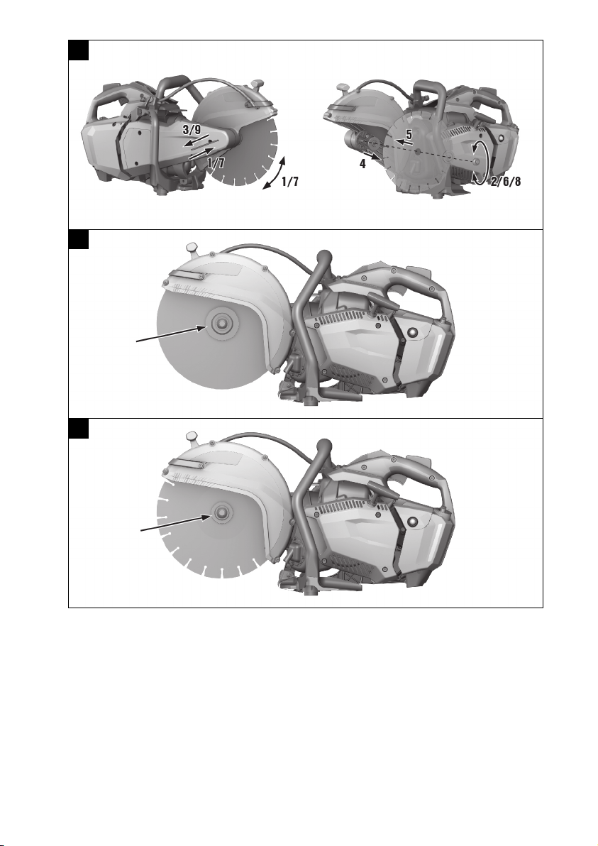
The numbering reflects the sequence of operations shown in the illustrations and may deviate
from the steps described in the text
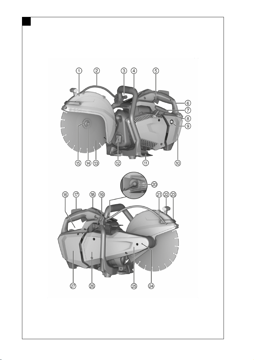
Item reference numbers are used in the overview illustrations and refer to the numbers used in
the product overview section
This symbol is intended to draw special attention to certain points when handling the product.

2 English 2275356 *2275356*
1.3 Product-dependent symbols
1.3.1 Symbols on the product
The following symbols are used on the product:
Direction-of-rotation arrow on the guard
Engine stop position
Engine run position
Primer bulb
Full-throttle jet adjusting screw
Idling jet adjusting screw
Idling adjusting screw
Fuel mixture
Fuel-tank cap opening direction
Speed
Revolutions per minute
Diameter
Wear ear protection, eye protection, respiratory protection and a hard hat.
Wear protective gloves
Wear protective footwear
Wireless data transfer
1.4 Adhesive labels on the machine
Warning signs
General hazard
Warning: Risk of fire due to flying sparks
Warning: Risk of kickback
Warning: Do not inhale toxic vapors or exhaust fumes
Maximum spindle speed
Warning: Hot surface
Prohibition symbols
Do not use toothed cutting discs
Do not use damaged cutting discs

*2275356* 2275356 English 3
No smoking, no naked flame
1.5 Product information
products are designed for professional users and only trained, authorized personnel are
permitted to operate, service and maintain the products. This personnel must be specifically informed about
the possible hazards. The product and its ancillary equipment can present hazards if used incorrectly by
untrained personnel or if used not in accordance with the intended use.
The type designation and serial number are printed on the rating plate.
▶Write down the serial number in the table below. You will be required to state the product details when
contacting Hilti Service or your local Hilti organization to inquire about the product.
Product information
Cut-off saw DSH 600-X
Generation 01
Serial no.
1.6 Declaration of conformity
We declare, on our sole responsibility, that the product described here complies with the applicable directives
and standards. A copy of the declaration of conformity can be found at the end of this documentation.
The technical documentation is filed here:
Hilti Entwicklungsgesellschaft mbH | Tool Certification | Hiltistrasse 6 | 86916 Kaufering, Germany
2 Safety
2.1 General safety instructions
WARNING Study all safety instructions and other instructions, images and technical data with which
this product is provided. Failure to comply with the instructions below can result in serious injuries or death.
Keep all safety precautions and instructions for future reference.
2.2 Personal safety
▶Use the right tool for the job. Do not use the tool for purposes for which it was not intended. Use it only
as directed and when in technically faultless condition.
▶Never tamper with or modify the power tool in any way.
▶Only persons who are familiar with it, who have been trained on how to use it safely and who understand
the resulting hazards are permitted to use the product. The product is not intended for use by children.
▶Stay alert, watch what you are doing and use common sense when operating the product. Do not use
the product while you are tired or under the influence of drugs, alcohol or medication. A moment of
inattention while operating the product can result in serious personal injury.
▶Maintain a firm grip on the cut-off saw with both hands and position your body and arms to absorb
kickback forces. Always use the auxiliary handle, if provided, for maximum control over kickback
forces or torque reaction during start-up. By adopting suitable precautionary measures the operator
can control the kickback and reaction forces.
▶The use of cutting tools other than those described in this documentation is not permitted.
▶For wet cutting, do not use synthetically bonded abrasive discs unless the discs have been specified for
such use by the disc manufacturer.
▶The use of reducing sleeves and/or knot wheel brushes is not permitted.
▶The user and persons in the vicinity must wear suitable protective goggles, a hard hat, ear defenders,
protective gloves, protective footwear and light respiratory protection while the tool is in use.
▶Wear eye protection. Flying fragments present a risk of injury to the body and eyes.
▶Dust from materials such as paint containing lead, some types of wood, minerals and metal can be
harmful to health. Contact with or inhalation of the dust can cause allergic reactions and/or respiratory or
other diseases to the operator or bystanders. To reduce the amount of dust produced when cutting, we
recommend use of the wet cutting method. Make sure that the workplace is well ventilated. It is advisable
to wear a filter class P2 dust mask. Comply with national regulations applicable to the materials you will
be working with.

4 English 2275356 *2275356*
▶Always hold the tool firmly with both hands on the grips provided. Keep the grips clean, dry and free
from oil and grease.
▶If there is an unwanted increase in speed, set the run/stop switch to the "stop" position. Contact Hilti
Service.
▶Releasing the throttle safety grip when the tool is running at full speed causes the tool to tip forward
slightly due to the braking torque. Be prepared for this and grip the tool securely with both hands on the
grips provided.
▶Never use the tool without the guard (hood). Adjust the guard to the correct position. The guard must be
securely attached and positioned for maximum safety, so that the smallest possible part of the cutting
disc is exposed to the operator. Make sure that sparks created during use do not present a hazard. The
guard helps to protect the operator from broken disc fragments, inadvertent contact with the cutting disc
and uncontrolled flying sparks.
▶Do not touch rotating parts – risk of injury!
▶Maintain a firm footing and balance at all times. This will allow you to control the product better, even
in unexpected situations. Avoid unusual postures. When using the product, hold it in such a way that
dust, flying sparks and possible flying fragments of the accessory tool or workpiece cannot hit you. Do
not lean over the cutting disc.
▶Wear suitable work clothes. Do not wear jewelry or loose clothing. Keep your hair, clothing and gloves
away from moving parts. Loose clothes, jewelry or long hair can be snagged by moving parts.
▶If the product or the cutting disc has been dropped or has fallen, check the product and the cutting disc
for damage. Change the cutting disc if necessary.
▶Switch the product off before adjusting the guard or changing the cutting disc.
▶Wear protective gloves also when changing the cutting disc. Touching the cutting disc presents a risk of
injury (cuts or burns).
▶Avoid skin contact with the slurry created when using the wet cutting method.
▶Cutting material containing asbestos is not permissible.
▶Take breaks between working and do relaxation and finger exercises to improve the blood circulation in
your fingers. Exposure to vibration during long periods of work can lead to disorders of the blood vessels
and nervous system in the fingers, hands and wrists.
▶Consult the responsible structural engineer, architect or person in charge of the building project before
starting work. Slits cut into load-bearing walls or other structures can influence the statics of the structure,
especially when reinforcing bars or load-bearing components are cut.
▶If work involves break-through, always secure the area on the side opposite where the work is carried
out. Pieces of debris could drop out and/or fall down and injure other persons.
▶Never leave the product running while unattended.
▶Switch the engine off and wait until the cutting disc has come to a complete standstill before placing the
product on the ground, moving it to the next working position, or transporting it.
▶Make sure that the pump cover is installed if you operate the product without an external water pump.
▶Switch the product off after use.
▶Maintain the product carefully. Check whether parts are broken or damaged to the extent that the
product is not in full working order. Have damaged parts repaired before using the product.
▶To reduce the risk of injury, use only genuine Hilti tools and accessories.
▶Have the product repaired only by qualified specialists using only genuine Hilti spare parts. The safety of
the product can thus be maintained.
▶Comply with national health and safety requirements.
2.3 Electrical safety
▶Before beginning work, check the working area for concealed electric cables or gas and water pipes.
External metal parts of the machine may give you an electric shock if you damage an electric cable
accidentally.
▶Organize in advance the work to be performed, after examining the location. Check whether warning
signs have to be set up and a safe working distance from other persons defined.
2.4 Safety at the workplace
▶Ensure that the workplace is well lit.
▶Don’t work in closed rooms. Carbon monoxide, unburned hydrocarbons and benzene in the exhaust gas
may cause asphyxiation.

*2275356* 2275356 English 5
▶Keep the workplace tidy. Objects which could cause injury should be removed from the working area.
Untidiness at the workplace can lead to accidents.
▶Hot exhaust gases containing sparks or sparks generated by the cutting operation may cause fire or
explosion. Make sure that the sparks generated do not ignite flammable (gasoline, dry grass, etc.) or
explosive (gas, etc.) substances.
▶After installing the water pump, make sure that the screws are tightened to the recommended tightening
torque.
▶Before fitting the water pump, check to ensure that the maximum permitted water supply pressure of 6
bar is not exceeded.
2.5 Liquids (gasoline and oil) and vapors
▶The inhalation of gasoline vapors and skin contact with gasoline may be hazardous to the health.
▶Avoid direct skin contact with gasoline. Wear protective gloves.
▶If your clothing becomes soiled with gasoline, it is essential to change your clothing.
▶Ensure that the workplace is well ventilated in order to avoid breathing in gasoline fumes.
▶Use a fuel canister that complies with the applicable regulations.
▶Don’t refuel the product while the engine is running. Wait until the engine has cooled down.
▶Never smoke while refueling; there is a risk of fire and explosion.
▶Do not refuel the product in the area where you are working (move at least 3 meters/10 feet clear of the
workplace). When refueling, take care to avoid fuel spillage. Use a suitable funnel.
▶Avoid inhaling gasoline vapors and exhaust fumes. Take care to ensure adequate ventilation.
▶Don’t use the gasoline or other flammable liquids for cleaning.
2.6 Cutting work using cutting discs
▶Use only cutting discs with a rated maximum permissible speed at least as high as the maximum spindle
speed.
▶Check that the outside diameter and the thickness of the cutting disc comply with the capacity rating of
the product.
▶Never use cutting discs that are damaged, run untrue or vibrate.
▶Do not use damaged diamond cutting discs (cracks in the steel disc, broken or polished segments,
damaged arbor hole, bent or distorted steel disc, heavy discoloration due to overheating, steel disc worn
away beneath the segments, diamond segments with no lateral overhang, etc.).
▶Do not use toothed accessory cutting tools (e.g. toothed saw blades).
▶When fitting the cutting disc, always take care to ensure that the disc’s specified direction of rotation
corresponds to the direction of rotation of the spindle. Always install only one cutting disc.
▶The cutting disc and flange or any other accessory must fit the arbor of the product exactly. Cutting
discs with arbor holes that do not match the mounting hardware of the product will run out of balance,
vibrate excessively and can lead to loss of control and to breakage of the cutting disc.
▶Always use an undamaged clamping flange of the correct diameter which fits the cutting disc used.
The correctly fitting clamping flange supports the cutting disc and thus reduces the possibility of disc
breakage.
▶Guide the product smoothly and do not apply lateral pressure to the cutting disc. Always bring the cutting
disc into contact with the workpiece at right angles. Don’t attempt to alter the line of cut by applying
lateral pressure or by bending the cutting disc while cutting is in progress.
▶Abrasive cutting discs which are used for wet cutting must be used up the same day as long periods of
exposure to moisture have a negative effect on the strength of the disc.
▶Never install a saw blade for cutting wood.
▶Use only cutting discs that comply with the existing standards for cutting discs.
▶Prior to installation and before use, check the cutting disc for damage. Do not install a damaged cutting
disc. Comply with the requirements stated by the manufacturer of the cutting disc.
▶Observe the expiry date for resin-bonded cutting discs and don’t use the discs after this date.

6 English 2275356 *2275356*
3 Description
3.1 Product overview
3.1.1 Gasoline-powered cut-off saw 1
@Guard
;Water supply
=Water connection
%Front grip
&Throttle trigger
(Rear grip
)Recoil starter pull handle
+Fuel tank cap
§Primer bulb
/Fuel level indicator
:Footplate
∙Exhaust discharge with spark filter
$Cutting disc
£Clamping screw
|Clamping flange
¡Rating plate
QSafety grip with integrated brake actuation
WStart/stop switch with integrated half-throttle
lock
EWater cock
RSpark plug connector
TCleaning screw for water nozzle
ZGrip for guard adjustment
UCurved water distributor with integrated wa-
ter nozzles
IHole for locking pin for changing cutting
discs
OSaw arm
PPump cover
ÜAir filter cover
3.2 Intended use
The product described is a gasoline-powered cut-off saw for the wet or dry cutting of asphalt, mineral
construction materials or metals using diamond cutting discs or abrasive cutting discs.
The saw is not suitable for use in environments where there is risk of fire or explosion.
3.3 Possible misuse
▶“Shoveling” with the gasoline-powered saw is not permissible.
3.4 Instructions for use
• Use of the wet cutting method is preferable in order to reduce the amount of dust produced when cutting.
By using the self-priming water pump (accessory) you can work without need for a water supply hose.
The water can be drawn, for example, directly from a container.
• Do not cut right through the workpiece in one pass. Move the saw back and forward several times until
it gradually reaches the desired cutting depth.
• To avoid damaging the diamond cutting disc when dry cutting, lift the disc out of the cut for approx. 10
seconds every 30 to 60 seconds while the saw is still running.
• Resharpen a polished diamond disc (i.e. when no diamonds project from the segment matrix) by cutting
with the disc in a very abrasive material such as sandstone.

*2275356* 2275356 English 7
3.5 Cutting disc specifications
Diamond discs in accordance with EN 13236 are to be used with the product. Synthetic resin-bonded, fiber-
reinforced cutting discs in accordance with EN 12413 (straight, not dish-shaped, type 41) may also be used
with the product for working on metals.
The disc mounting instructions and instructions for use issued by the cutting disc manufacturer must be
observed.
3.6 Items supplied
DSH 600-X gasoline-powered saw, tools set, DSH 600-X wear parts and consumables set, operating
instructions.
Other system products approved for use with this product can be found at your local Hilti Store or at:
www.hilti.group
3.7 Saw blade brake
The product is equipped with an integrated saw blade brake to increase operator safety.
The saw blade is braked to a standstill in a maximum of 10 seconds after the throttle safety grip is released.
Releasing the throttle safety grip when the tool is running at full speed causes the tool to flick forward
slightly because of the braking torque. So hold the tool firmly with both hands on the grips provided.
3.8 Consumables and wearing parts
• Air filter
• Cord
• Starter
• Fuel filter
• Spark plug
• Tool set
• Cylinder set
• Mounting screw assy.
• Flange for abrasive cutting disc (with integral centering ring 20 mm/1")
• Flange for diamond cutting disc (with integrated centering ring 20 mm/1")
4 Technical data
4.1 Gasoline-powered cut-off saw DSH 600-X
Engine displacement 63.3 cm³
Weight with diamond disc flange, without cutting disc, tank
empty
9.85 kg
Rated power at 8500 rpm in accordance with ISO 7293 3.2 kW
Maximum spindle speed 5,080 /min
Max. rotational speed of the cutting disc 5,080 /min
Maximum cutting depth 120 mm
Carburetor Walbro; model: WT-1203
4.2 Additional technical data
Engine type Single-cylinder, air-cooled two-
stroke engine
Maximum engine speed 8,700 /min
Idle speed 2900 ± 200 /min
Ignition (type) Electronic
Electrode gap 0.7 mm
Spark plug NGK, type: CMR7A

8 English 2275356 *2275356*
Tightening torque for fitting the spark plug 12 Nm
Fuel mixture API-TC oil 2% (1:50)
Tank capacity 0.87 ℓ
Cutting disc arbor size / diameter of centering bush 20 mm
Cutting disc arbor size / diameter of centering bush 25.4 mm
Minimum flange outside diameter for diamond cutting
discs (only for steel-core discs; the flanges are marked with
“FOR DIAMOND ABRASIVE STEEL CORE WHEELS ONLY”)
60 mm
Minimum flange outside diameter for abrasive cutting
discs (composite discs)
78 mm
Maximum disc outside diameter 300 mm
Maximum disc outside diameter 12 in
Maximum nominal disc thickness (only for steel core discs) 4.5 mm
Maximum nominal disc thickness (composite discs) 4.0 mm
Tightening torque for fitting the cutting disc 25 Nm
4.3 Noise information and vibration values
The sound pressure and vibration values given in these instructions have been measured in accordance with
a standardized test and may be used to compare one gasoline-powered saw with another. They may be
used for a preliminary assessment of exposure.
The data given represents the main applications of the machine. However, if the machine is used for different
applications, with different accessory tools or is poorly maintained, the data may vary. This may significantly
increase exposure over the total working period.
An accurate estimation of exposure should also take into account the times when the machine is switched
off, or when it is running but not actually being used for a job. This may significantly reduce exposure over
the total working period.
Identify additional safety measures to protect the operator from the effects of noise and/or vibration, for
example: Maintaining the machine and accessory tools, keeping the hands warm and organizing work
patterns.
Noise emission values
Emission sound pressure level in accordance with EN ISO 19432-1 (ISO
11201) (Lpa,eq)
102 dB(A)
Uncertainty 1.6 dB(A)
Measured sound power level in accordance with 2000/14/EC (ISO 3744)
(Lwa)
113 dB/1pW
Uncertainty 1.1 dB/1pW
Guaranteed sound power level in accordance with 2000/14/EC (ISO 3744)
(Lwa)
115 dB/1pW
Total vibration
The sound pressure level and the vibration values were determined allowing for 1/7 no-load operation and
6/7 full-load operation.
EN ISO 19432-1 vibration emission value at grip, front (ahv,eq)≤ 2.5 m/s²
Uncertainty 1.8 m/s²
EN ISO 19432-1 vibration emission value at grip, rear (ahv,eq)≤ 2.5 m/s²
Uncertainty 0.9 m/s²
5 Before use
5.1 Fuel
The two-stroke engine runs on a mixture of gasoline and oil. The quality of the fuel mixture decisively
influences operation and life expectancy of the engine.

*2275356* 2275356 English 9
WARNING
Risk of injury. The inhalation of gasoline vapors and skin contact with gasoline may be hazardous to the
health.
▶Avoid direct skin contact with gasoline. Wear protective gloves.
▶If your clothing becomes soiled with gasoline, it is essential to change your clothing.
▶Ensure that the workplace is well ventilated in order to avoid breathing in gasoline fumes.
▶Use a fuel container that complies with the applicable regulations.
5.1.1 Using two-stroke oil
▶Use good-quality, two-stroke oil for air-cooled engines that meets at least the API-TC specification.
5.1.2 Gasoline
▶Use regular or super gasoline with an octane rating of at least 89 ROZ.
The alcohol content (e.g. ethanol, methanol or others) of the fuel used must not exceed 10%,
otherwise the life expectancy of the engine will be greatly reduced.
5.1.3 Mixing fuel
The engine will suffer damage if run with fuel mixed in the wrong ratio or with unsuitable oil.
Use a mixing ratio of 1:50. This corresponds to 1 part good-quality two-stroke oil that complies with
the API-TC specification and 50 parts gasoline (e.g. 100 ml oil and 5 liters of gasoline mixed in a
suitable canister).
1. Pour the required quantity of two-stroke oil into the fuel canister.
2. Pour the gasoline into the fuel canister.
3. Close the fuel canister.
4. Mix the fuel by shaking the fuel canister.
If the quality of the two-stroke oil or the gasoline is unknown, then increase the mixing ratio to 1:25.
5.1.4 Filling the fuel tank
1. Mix the fuel (two-stroke oil / gasoline mixture) by shaking the fuel container.
2. Place the product in a steady upright position.
3. Open the fuel tank by turning the cap counterclockwise and then removing the cap.
4. Fill the tank slowly using a funnel.
5. Close the fuel tank by fitting the cap and then turning it clockwise.
6. Close the fuel canister.
5.2 Assembly and adjustment
WARNING
Risk of injury. Contact with the rotating cutting disc can lead to injury. Hot parts of the machine or a hot
cutting disc may cause burning injuries.
▶Before fitting or adjusting any parts of the product, make sure that the engine is switched off, that the
cutting disc has completely stopped rotating and that the product has cooled down.
▶Wear protective gloves.

10 English 2275356 *2275356*
5.2.1 Fitting a cutting disc 2,3,4
WARNING
Risk of injury and damage. Unsuitable cutting discs or unsuitable parts used to secure the disc can suffer
irreparable damage during operation or lead to loss of control of the product or breakage of the accessory tool.
▶Make sure that the cutting disc’s maximum permissible speed is at least as high as the maximum spindle
speed stated on the product. Use only cutting discs, flanges and screws that are suitable for your
product.
▶Use only cutting discs with a mounting hole diameter of 20 mm or 25.4 mm (1") and that are a correct fit
on the centering bushing.
▶Use only the large flange with diameter 78 mm (3") to secure an abrasive cutting disc.
WARNING
Risk of injury and damage. Damaged cutting discs may break.
▶If the cutting disc has been subjected to an impact, check the disc for damage and replace it if necessary.
▶Never use cutting discs that are damaged, run untrue or vibrate.
▶Don’t use synthetic resin-bonded fiber-reinforced cutting discs which have exceeded their use-by date
or already softened due to water absorption.
1. Insert the locking pin in the hole in the drive belt cover and turn the cutting disc until the locking pin
engages.
2. Release the securing screw by turning the screw counterclockwise with the wrench and then remove the
screw and washer.
3. Remove the locking pin.
4. Remove the clamping flange and the cutting disc.
5. Check that the diameter of the arbor hole in the cutting disc to be fitted matches the centering collar of
the cutting disc mounting flange.
The mounting flange has a 20 mm diameter centering collar on one side and a 25.4 mm (1")
diameter centering collar on the other side.
6. Clean the clamping and centering surfaces on the tool and on the cutting disc.
7. Select one of the following alternatives.
Alternative 1/2
▶Use only the large flange to secure the abrasive cutting disc.
Alternative 2/2
▶Use the small flange with diamond cutting discs in order to utilize the full cutting depth.
8. Place the cutting disc with centering collar on the drive arbor and check that the direction of rotation is
correct.
▶The direction-of-rotation arrow on the cutting disc must match the direction of rotation indicated on
the tool.
9. Place the clamping flange and washer on the drive arbor and tighten the securing screw by turning it
clockwise.
10. Insert the locking pin in the locking hole in the drive belt cover and turn the cutting disc until the locking
pin engages.
11. Securely tighten the clamping screw (tightening torque: 25 Nm).
12. Remove the locking pin.
CAUTION
Risk of injury and damage. Damaged accessory tools can break.
▶Never use an accessory tools that is damaged, runs out of true or vibrates.
▶Keep clear of the danger zone.
13. After fitting a new cutting disc, run the tool at full speed under no load for approximately 1 minute.

*2275356* 2275356 English 11
5.2.2 Adjusting the guard
WARNING
Risk of injury. Contact with the cutting disc and flying fragments or sparks can cause injury to persons.
▶Adjust the guard so that flying particles or fragments of the material removed and flying sparks are
directed away from the operator and the product.
▶Hold the guard by the grip provided and rotate it to the desired position.
Make sure that the opening of the blade guard is not toward the user.
5.2.3 Fitting the water pump (accessory) 5
1. Switch the product off.
2. Release the three pump cover retaining screws, remove the parts and store the pump cover in a safe
place.
The pump cover must be fitted if the tool is used without the water pump.
3. Hold the water pump in position and turn the cutting disc slightly to bring the splines of water pump and
clutch bell into alignment so that the splines engage.
▶The position is keyed so it is not possible to position the pump incorrectly.
4. Install the three securing screws and tighten the securing screws.
▶Tightening torque: 8 Nm
5. Connect the pump hose to the hose connector on the saw.
6. Remove the protective cap from the end of the water connection hose.
7. Make sure that the water pressure in the water supply line is max. 6 bar.
▶Reduce the water pressure as necessary.
8. Connect the water pump to the water supply or immerse the end of the suction hose in a container filled
with water.
Fit the protective cap to the end of the water connection hose when the water pump is not
connected to a water supply.
5.2.4 Removing the water pump (accessory)
1. Switch the product off.
2. Disconnect the water supply from the water pump.
3. Fit the protective cap to the end of the water connection hose.
4. Disconnect the connector between the pump and the tool.
5. Release the three fastening screws on the pump and then remove the pump.
6. Place the pump cover in position.
7. Install the 3 securing screws and tighten the securing screws.
▶Tightening torque: 4 Nm
5.2.5 Fitting the wheel set (accessory) 6
1. Slacken the two bottom securing screws on the metal guard.
2. Secure the base plate with the two screws.
3. Secure the wheels and washers with the screws on both sides of the base plate.
6 Operation
6.1 Starting the engine 7
DANGER
Risk of asphyxiation. Carbon monoxide, unburned hydrocarbons and benzene in the exhaust gas may
cause asphyxiation.
▶Don’t work in closed rooms, trenches or pits and make sure the area is well ventilated.

12 English 2275356 *2275356*
WARNING
Risk of burning injury. The exhaust system gets extremely hot when the engine is running. It stays hot for a
long time after the engine is switched off.
▶Wear protective gloves and avoid touching the exhaust system.
▶Do not lay the product down on flammable material while hot.
WARNING
Risk of injury. A damaged exhaust system raises the noise level above the permissible limit and increases
the risk of suffering hearing damage.
▶Never use the product if the exhaust system is damaged, missing or if it has been tampered with.
WARNING
Risk of injury if product is operated without the cover for the water pump correctly installed Touching
the water pump connection during operation leads to injuries.
▶Before starting operation, make sure that the cover for the water pup is correctly installed.
WARNING
Risk of injury due to substances and gases igniting. Burns and fatalities can result.
▶Do not use the product if flammable substances and gases are present.
▶Ensure adequate ventilation.
CAUTION
Risk of burns or injury through pinching the fingers when the water pump is fitted. Touching the pump
housing can cause burning injuries.
▶Hold the forward grip only at the top and on the left side.
1. Press and hold down the throttle safety grip.
2. Press and hold down the throttle trigger.
3. Move the start/stop switch to the “start” position.
4. Release the throttle safety grip and throttle trigger.
▶The half-throttle position is activated.
5. Squeeze the primer bulb 2 to 3 times to fill the primer pump bulb with fuel only when starting with the
engine cold.
6. Check that the cutting disc is free to rotate.
7. Place your left foot on the footplate.
8. Pull the recoil starter pull handle slowly with your right hand until resistance is perceptible.
9. Vigorously pull the recoil starter pull handle.
10. Repeat this procedure until the engine fires.
11. Briefly press the throttle trigger as soon as the engine fires.
▶This disengages the half-throttle position and the engine will idle when the throttle trigger is released.
6.2 Checks after starting the engine
1. Check that the cutting disc remains stationary when the engine is idling and, after briefly running at full
speed, that the disc again comes to a complete standstill.
▶Readjust (reduce) the idling speed if the cutting disc doesn’t stop rotating when the engine is idling.
If this is not possible, please bring the product to Hilti Service.
2. Check that the start/stop switch is functioning correctly. Move the start/stop switch to the “stop” position.
3. If the engine doesn’t stop, compress the primer bulb. If the engine still doesn’t stop, pull the spark plug
connector off the spark plug and bring the product to Hilti Service.
6.3 Switching the engine off
WARNING
Risk of injury. A rotating cutting disc can break or shatter, possibly resulting in flying fragments.
▶Allow the rotating cutting disc to come to a complete standstill before you lay the saw down.
Other manuals for DSH 600-X
2
Table of contents
Other Hilti Saw manuals

Hilti
Hilti SCW 18-A User manual

Hilti
Hilti DSH 900 User manual

Hilti
Hilti WSR 36-A User manual

Hilti
Hilti SR 30-A36 User manual

Hilti
Hilti SCW 70 User manual

Hilti
Hilti WSC 70 User manual

Hilti
Hilti DSF 1030-TS User manual

Hilti
Hilti WSC 70 User manual

Hilti
Hilti DST 10-E User manual

Hilti
Hilti SC 70W-A User manual

Hilti
Hilti WSC 85 User manual

Hilti
Hilti SR 2-A12 User manual

Hilti
Hilti SCM 18-A User manual

Hilti
Hilti Nuron SC 30WR-22 User manual

Hilti
Hilti DSH 700 User manual

Hilti
Hilti WSR 900-PE User manual

Hilti
Hilti DSW 3018-E User manual

Hilti
Hilti DSW 1510-CA User manual

Hilti
Hilti DSH 900 User manual

Hilti
Hilti DSH 700 User manual