IMER MASONRY 500 Datasheet


ç4jIMER INTERNATIONAL S.p.A.
MASONRY500
Thank-you for purchasinga Masonry 500 from an Imer U.S.A. dealer. Yourdecisionis an intelligentone.
There is no other sawing machine in the world which deliversthe benefitsand features ofthe Masonry350F:
-Extremelyrigid, mig
weldedbarsteelframe.
-5.5H.P. electricmotor.
-Sigle
armforlargerworking space.
-Extremely rigid worktable foraprecise cutting.
At IMER U.S.A.we continuallysearch forwaysto better serve ourcustomers.Should you have an idea orthought to
sharewith usregardingthis productwe wouldappreciatehearingfromyou. Ourmotto is "Tools andServices for the
21stCentury" We look forward todeliveringthe goods.
Thank youagain for your purchase.
MaceT.Coleman, Jr.
President, Imer
USA,Inc.
IMER
WEST
207 LawrenceAvenue
So.SanFrancisco, CA94080
Tel 650-872 -2200
Fax650 -873-6482
2
IMEREAST
221Westhampton Place
Capitol Heights,MD20743
Tel 301 -336-3700
Fax301 -
336- 6681
1.
Carriage locking lever.
2. Spray guard
3. Electric motor
4. Blade aupport
5. waterpump
6. Guide
7. Contactor
8. Worktable
9. Water tank
10. Blade cover
II.Adjuatment crank.
12.Workpiece
13. Blade
14. Frame
15. Earth acrew
16.Pedal.
17. Head atop bolt.
18. Bladeguard.
1!
PDF compression, OCR, web-optimization with CVISION's PdfCompressor
Dear
Customer;
Con
gratulationsonyour
choice of
purchase: this IMER saw, the
resultofyears ofexperience,isafully reliable machine andis
equippedwith thelatest technicalinnovations.
/j\-WORKINGINSAFETY
Toworkin completesafety, readthe followinginstructions
carefully.
-ThisOPERATION ANDMAINTENANCEmanualmustbe
kept
onsite
by
the
personincharge, e.g.theSITE
FOREMAN,
andmust
always
beavailableforconsultation.
-
Thismanualistobeconsideredanintegralpart
ofthe
machine,
and
itmustbepreserved
forfuturereference
(EN292/2)throughout
the
machine'snormalworking
life. Ifthe manualisdamagedorlost,a
replacementmay be requested
from thesaw manufacturer
-
Themanualcontains
important
information regarding
sitepreparation,
installation,
machine
use,maintenance
procedures
andrequests
for
spare parts.Nevertheless,
theinstallerand the
operatormust both
haveadequateexperience
and knowledge
ofthemachine priorto
use.
-Toguaranteecompletesafetyoftheoperator, safe operation
and
longlifeof
equipment,
followtheinstructionsinthismanual
carefully,
andobserveallsafety
standards
currently
inforceforthe
prevention
ofaccidents atwork. Use personal protection (safety footwear,
suitable
clothing,gloves,goggles,etc.).
.4'..-Safetyglasses ora
protective visormustbewornatall
times.
/j\-Ear
protection
mustbewornatalltimes.
/j -MAKESURETHAT WARNING SIGNS AREALWAYS
LEGIBLE.
- Itis strictly forbidden tocarry outany form of
modification tothesteelstructure orworkingpartsofthe
machine.
-
IMERINTERNATIONAL declinesall
responsibilityfornon-compliance
with laws andstandards governingtheuseofthis equipment,
in
particular;improperuse,defective power
supply,
lackof
maintenance,
unauthorised
modifications,
andpartial
ortotalfailuretoobservethe
instructionscontainedinthismanual.
IMERINTERNATIONALisentitledto
modifythe
characteristicsofthe
sawing
machineand/orthecontentsofthismanualwithout
necessarily
updatingprevious
machinesand/ormanuals.
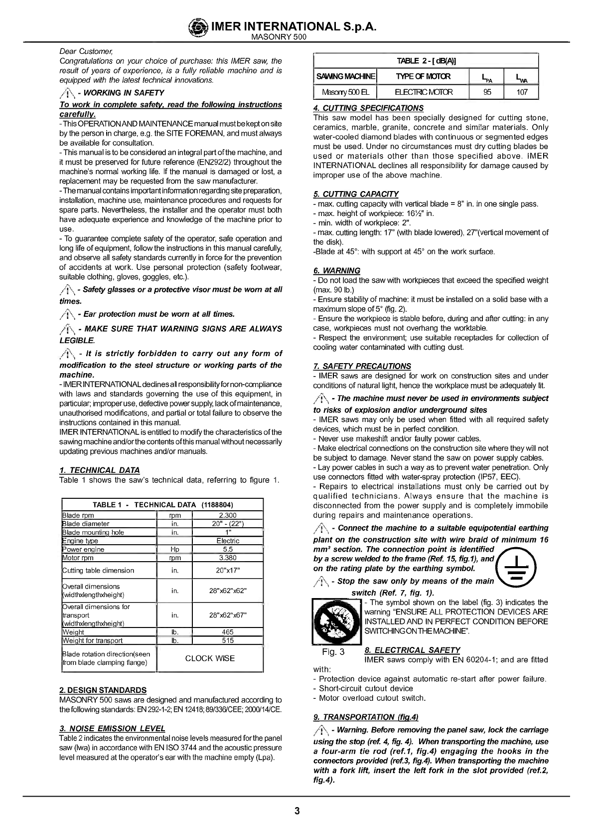
1. TECHNICAL DATA
Table 1 shows thesaw'stechnical data, referring tofigure 1.
TABLEI . TECHNICALDATA (1188804)
llade
rpm rpm 2.300
Blade diameter in. 20"-(22")
Blade mountinghole in. 1"
Enginetype Electric
'owerengine Hp 5.5
otorrpm rpm 3.360
utting
table dimension in. 20"x17"
)veralldimensions
widthslengthxheight) .
in. 2B"x62"x62"
)veralldimensions for
transport
widthslengthxheight) in. 2B"x62"x67"
Weight lb. 465
Weightfortmnsport lb. 515
Blade rotation direction(seen
romblade clampingflange) CLOCKWISE
2.DESIGNSTANDARDS
MASONRY500sawsare
designedandmanufactured
according
to
the
following
standards: EN
292-1-2;
EN12418;89/336/CEE;
2000/14/CE.
3.NOISEEMISSION LEVEL
Table2indicates theenvironmental noiselevelsmeasured forthe
panel
saw(Iwa)
inaccordancewith EN ISO3744andtheacoustic
pressure
levelmeasuredatthe
operator's
earwiththemachine
empty(Lpa).
I Ti4BLE2-[dB(P4]
S6WNGMACHINE TYPEGFIVO1UI LPA Lw,,
Fvhsonysfx)EL ELECTRICFvtJ1CR 95 107
4. CUTTING SPECIFICATIONS
This saw model has been speciallydesigned
forcuttingstone,
ceramics, marble,granite, concreteand similar materials. Only
water-cooled diamond blades with continuous or
segmented edges
must be used. Under nocircumstances must drycutting blades be
used ormaterials otherthan thosespecified above. IMER
INTERNATIONALdeclines allresponsibility for
damage caused by
improper useoftheabove machine.
5. CUTTING CAPACITY
-max.cullingcapacity
withverticalblade
=8"in.inone singlepass.
-max.height
of
workpiece:16Win.
-mm.widthof
workpiece:2".
-
max.cullinglength:17"
(withblade
lowered),27"(vertical
movementof
the disk).
-Bladeat45°: with support
at45° ontheworksurface.
6. WARNING
-Donotloadthesaw withworkpieces
thatexceedthespecifiedweight
(max.
90lb.)
-Ensure
stability
ofmachine:itmust beinstalledonasolid base witha
maximum
slopeof5°
(fig.2).
-Ensurethe
workpiece
isstablebefore,duringandafterculling:inany
case,workpiecesmust not
overhangtheworktable.
-Respecttheenvironment;use suitablereceptacles
forcollection of
coolingwatercontaminatedwith culling dust.
7. SAFETY PRECAUTIONS
-IMERsaws are designedforworkon constructionsites and under
conditionsofnaturallight,
hencethe
workplacemustbeadequately
lit.
-Themachinemustneverbeusedin environments subject
to risks of
explosion
andlor
underground
sites
-IMER saws may only
be used when filledwith all required safety
devices,
whichmustbein perfectcondition.
-Neveruse makeshiftand/orfaultypowercables.
-
Makeelectricalconnectionsontheconstructionsitewhere
theywillnot
besubjecttodamage. Neverstandthesawon powersupplycables.
-Laypower
cablesinsucha
way
asto
prevent
waterpenetration.Only
use connectorsfilled with water-sprayprotection(1P57, EEC).
-Repairs toelectricalinstallationsmust onlybe carriedout by
qualified technicians.
Always ensurethat the machine is
disconnected from thepowersupply
and is completely immobile
during repairs and maintenance operations.
-Connectthemachinetoasuitable
equipotential earthing
planton theconstructionsite with wirebraid ofminimum16
mm2section. Theconnection
point isidentified
by
ascrewwelded totheframe
(Ret15,fig.1),and I
on therating
platebythe
earthingsymbol. __
-Stopthesawonlybymeans ofthemain —
switch (Ref.7, fig. 1).
-Thesymbolshown onthelabel (fig. 3) indicatesthe
waming"ENSUREALL PROTECTIONDEVICESARE
INSTALLEDANDIN PERFECTCONDITIONBEFORE
ISWITCHING ONTHEMACHINE".
Fig. 3 &ELECTRICAL SAFETY
IMER saws comply with EN 60204-1; and arefilled
-Protection device against automatic re-start after power failure.
-Short-circuit cutout device
-Motoroverload cutout switch.
9. TRANSPORTATION
(fig.4)
-Warning. Before removingthe
panelsaw,lockthecarriage
using
the
stop(ret 4,fig.4). Whentransporting the
machine, use
a four-arm tierodfret
1,fig.4) engaging
thehooksinthe
connectors
providedfret3,fig.4).When transporting themachine
withaforklift, inserttheleftforkin theslot
provided fret2,
fig.4).
ctIMER INTERNATIONAL S.p.A.
MASONRY500
with:
3
PDF compression, OCR, web-optimization with CVISION's PdfCompressor

intoposition.
4
IMER INTERNATIONAL S.p.A.
MASONRY500
10. INSTALLATION(flg. 4)
-Liftthemachineoutofitspackageusingslingingequipment
with 4
ropelegs.Fixthehookstotherelative attachments.
-Installthemachineonacompletely
evenandstablesurface.
-Releasethe
carriage
fromtheleverthatsecuresittotheframe.
11. ELECTRICALCONNECTION
/\- Ensurethatthere is an overloadcutoutdevice
fitted up-lineon thepowerline.
-Ensurethatthe mains
voltagecorresponds tothat
specified
forthemachine: 230V/6OHz.Theelectrical power
cable must
be suitably
sizedtoavoid voltagedrops. Cable drumsmustnot
be used.
Connect the machine toan efficient earthing system.
Thesize ofthepower cablewiresmustbe based onoperating
current and length ofthe power line to prevent excessive
voltagedrops (ref.Table 3).
Cables used on construction sitesmustbefittedwith suitable
external sheathing thatis resistant to wear, crushing and
extremeweatherconditions (forexample HO7RN-F).
/\-Allpowersupply installationsmust complywith
CEI 64-8 standards(harmonised
documentCENELEC
HD384).
12.MACHINESTART-UP
Before connecting the machine tothe power supply:
1 -Ensurethatthe metal structure isconnected toanearthing
plantasindicated in Section 7 "Safety Precautions".
2-Ensurethat thetank contains sufficient cooling water.
3-Ensurethatthe
power
circuitcorresponds tothe
requirements
asindicated in Section 11 "Electrical connections"
4-Connect themachine tothe power supply
5-Pressthe black switch (Ref. 7, fig. 1).
/\-Ifrotating direction isopposite tothe arrowon the
guard, stopthe machine andreverse the two
wiresinside thefeedingplug: suchoperation
must be
carriedonbyreliablepersons
6-adjusttheflowofcooling waterbyturning thecocknext to
the blade guard(do notperform cutting without
water).
7-Check thatthedirection ofbladerotation corresponds tothat
indicated by
thearrowonthe blade guard.
8-Ifallisin order, proceed with cutting.
13.EMERGENCYSTOP
/\-Inan emergency,stopthe machine bypressing the
stopcontrolswitch.
/'\,- Themotor isfittedwith an overload cutoutdevice.
Ifthe motor overheats, itwillautomatically
shutdown.
Allowthemotortocooland
press
the blackswitch onthe
overload cutoutdevice torestart
(Ref. 7, fig. 1).
- The motorisprotectedagainstautomaticre-start
afterinterruptions due to power failure. To resume
operation, when powerisre-connected, pressthe black
switchonthe overloadcutoutdevice (Ref. 7,fig. 1).
14.BLADE INSTALLATION (Fig.5)
By
means ofa hexwrench no.10,unscrewthe5screwsthatlock
the
movingblade
guard(ref.3). Use ahexwrenchno.13toremove
thescrewthat locks theflangesonthedisc:thisscrewhasaleft-
handthread (nfl).Removethe mobile
flange(rif.2)
andcheckthat
the
flanges,
discshaft and bladearenot
damaged.
-Neverusewornblades orbladeswithmissingsegments.
/j\-Only usebladesthatare designed
for thenumberof
revolutions indicatedonthe machineratingplate.
-Check thatbladerotation
corresponds
tothatindicated
on the bladeguard.
Centrethebladeagainst
thefixedflange,position
themobile
flange
and tightenthesecuringscrew bymeansofa hexwrenchno.13
(turn clockwise).
Refitthe
moving
blade
guard,tightening
the5screws
(ref.3).
-Ensurethatthebladeguard (ref.3)
islockedsecurely
- WARNING!Anincorrectly installed blade,or a
screw insufficiently tightened can
provoke damagetothe machine orinjury , -.
topersons. .
Notethat the blademust have an -
external diameter of20"in. a central hole
diameterof1"in.andinex. thicknessof118"in. !.-
-Checkthatthe blade tobe usedis
suitable forthe material tobe cut.
/j\ -Donotusebladesforwood! (fig. 6). Fig. 6
15.USE
/\-Leaveaspace of5ft.around themachine toopera-
te in fullsafety.
-Do notallowotherpersons toapproach themachine during
cutting.
-Neverusethemachine infire-riskareas. Sparks cancausefire
or explosions.
-Makesurethat themachine isswitched offbefore positioning
orhandling.
-Alwaysensurethat the bladeisfree ofany contactbefore
start-up.
-Ensurecorrectinstallation ofallprotective devices.
Before starting work, fill thewatertank.
Top upduring operation
whenevernecessary: NB. the pumpsuction hosemust
alwaysremain immersed in water.
-Insert theplug in thepower socket.
- WARNING! Forsafety purposes the removal of
protective
guards
fromthemachine isstrictlyprohibited
The machine is protected against overload: this
protection triggers stopping the machine, afterwhich
thetime necessary
fortheoverloadtocool mustpass
before itispossible
torestartthe machine.
- WARNING!
Alwaysswitchoffthe machine before
carryingoutbladeadjustment.
15.1 VERTICAL MOVEMENT OFTHEDISK.
Toraiseorlower the
cutting wheel, turnthecrank
(ref.11,fig.1)
until thewheel is attherequired height above the
cutting table.
Thewheel canalsobe lowered bypressing the pedal (ref.16,
fig.1); when thepedal isreleased thecutting wheel willreturn to
theposition originally setusing thecrank.
/?\-Ensure that the lockinghandle is tightenedfully
before
starting work.
15.2POSITIONING FOR45°CUTS.
To machine a45° cut, it isnecessary tousethe45° support.
Placethe45°
support onthe
cuttingtableinthepositionrequired,
fixthesupport
tothecarriage bylocking theflywheel provided,
then positionthepiecetobecut,
afterwhich itis possibletostart
themotorandcommence cutting operations
15.3 CUTTING
Forsafe useofthe machine when cutting, pushthe carriage
forwards asthe cut advances, placingyour hands tothetwo
sidesofthecarriage. Never
pushdirectly onthepiecetobecut.
-Checkthat the bladeisalignedwith the cutting
line.
-Place the workpiece on the worktable (ref. 8,fig. 1), resting
firmly against
thestop.
-Starttheengine.
-Waituntilthewaterreachestheblade.
-Begin cutting.
-
Horizontalcuttingmovement iscarriedout
bypullingthe
carriage
towards the blade.
-
Ascutting
thickness
increases,thebladeissubjected
togreater
stress. Toavoid overloading
theengine, the
operator should
continually
checkbladefeed speed. The
speedwillalso depend
on the characteristicsofthe
material being
cut(hardness, toughness etc.).
PDF compression, OCR, web-optimization with CVISION's PdfCompressor
15.3.1 CUTTING WITH CUTTING WHEEL LOWERED
FROMABOVE.
Adjust the verticalheight byturningthe crank (ref.11, fig.1),
positionthepiece
tobecut,
startthepanel saw andcommence
cutting operations bypressing thepedal(ref.16, fig.1)tolower
the wheel from above.
15.3.2BLADECHANGE
Tochange thebladerefertosection14.
16. USING
22"IN.DIAMETER
CUTTING WHEEL.
hfan optional cutting wheel diameter22" in. isusedinstead of
thestandard wheel diameter 20'in., itisimportantthatthe
stop
boltbe calibrated to prevent interference between the wheel
and thecarriage
whentheheadisin the lowest position.
-Warning. The
panel
sawisfittedwitha stopboltto
stopthe cutting wheelin the lowest verticalposition.
This stopiscalibrated fora2O'in. cutting
wheel. If
you
areusing
a22"in.cuttingwheel,loosenthe bolt(ref. 17,
fig. 1), lowerthe wheeltothelowest
position, byturning
thecrank,then check, with the motor turned off, that
there isno interference between the cuttingwheeland
thepiece holder
carriagewhenthepedal is pressed.
Adjust thebolt, bringitintocontactwith the stopand
tightenthelocknut.
- Notethattheblade musthaveanexternal diameter
of22"in., a central hole diameter of 1"in. and max.
thickness of1I8'in.
17.MAINTENANCE
/j\-WARNING! Servicing must
alwaysbecarried outby
qualified technicians andonlyafterthe motorhas been
switchedoff.
-WARNING! Recommended product forcleaning
mechanical
parts: WD-40.
-Alwayskeep the guards
inproper working
order
and freefromdamage.Take particular
care toensure
that the blade guards are keptefficientand clean,
replacing
themifthey aredamaged
/i-As there is the continuous risk ofinadvertent
damage tothe electric cables, thesemustbe checked
regularly
each timebefore the machine isused.
Donotleavethemachine outside: itmust
always
be protected
from the weather.
Below isalistofthecleaningoperations thatmustbe carried
out atthe end ofeveryshift.
Empty the tank byremoving the drain plug. Remove
cutting
residue usinga jet
ofwater.
17.2TANK REMOVAL (Ref.Fig.7).
17.3WORKSURFACE CLEANING
Alwayskeep work surfacesclean. Residual dirt can impair
cutting precision.
17.4 GUIDE
RAIL
CLEANING
Itisgood practice toremove all traces ofdirtfromtheguides.
17.5 CLEANINGAND MAINTENANCEOFCOOLING CIRCUIT
-Ifwaterdoesnotreachtheblade
stopthemachineimmediately
to
avoidblade
damage.
-After
switching
offthemachineensurethatthewaterlevelissufficient
—
Checkthatthereiswaterinthe
pumpbyunscrewing
the
connector,
and ifnecessarytopup untilwaterflows out(fig.10).
- WARNING Beforestarting thepanel
sawforthe first
time,orwhenstarting
itafter
longperiods ofinactivity, fill
the
pump with waterasdescribedabove
-Attheendof
everyshift,
unscrewthe suctionhosefilterand clean
it. Then,circulatesome waterthrough it placing insidea bucketof
clean water.
CIRCUIT
-
Ifwaterdoesnotreach thebladestopthemachine immediately
toavoid blade
damage.
-
Afterswitching offthemachine ensurethat thewaterlevel is
sufficient.
-Ifnecessary,afterdisconnecting themachine fromthepower
supply check thatthe
tap, hoseandpump filterarenotblocked
17.7TENSIONING THEDRIVEBELT(fig. 8)
-Switch offtheelectricmotor and remove the plug from the
power supply.
-Unscrew the 4screwsthat secure the movable beltguard
(ref. 1).
-Loosen the4(ref. 2)screws thatclamptheelectric motorto
the blade support.
-
Tensionthebelt
using
thenut
(ref. 4):apply
aforceofaboutF=141b.
tothecentreofthefreesectionofthe
belt,
thearrowshouldbeabout
F=1/4'in.(fig.9).
-Tighten the screws on the electric motor, checking the
alignment ofthemotor
pulley andtheblade pulley
-Refittheguard and lock itusing the4screws.
-Toavoid
shortening thelifeofthebelt, thebearings
andthe blade shaft,donotovertension the belt.Finally,
checkthetwopulleysarealigned
17.8DRIVEBELTREPLACEMENT
Repeat theoperations described in section
17.6, replacing the
beltbefore tensioning it.
17.9 REPAIRS
/?\-Do notstartthe sawduring repair
work.
Onlyuse
genuine IMER spare parts anddo not
modifythem.
/\-Iftheguards are removedtocarryoutrepairs, they
mustberefitted
properly
whentherepair workisfinished.
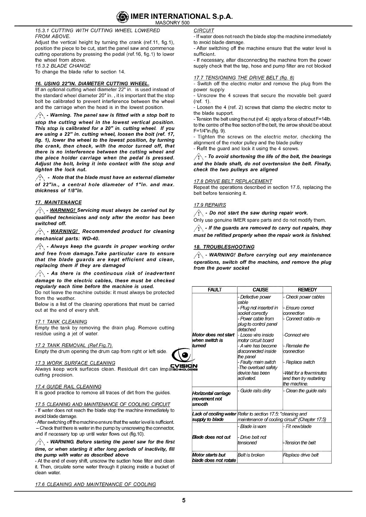
18. TROUBLESHOOTING
-WARNING!Before
carryingout anymaintenance
operations,switch offthe machine,andremove the plug
fromthe powersocket
FAULT CAUSE RENEDY
1otorcbesnotstart
i'Menswitchis
turned
-
Defective povter
cable
-
Plugnotinsertedin
socket
correctly
-Povrcablefrom
plugtocontrol panel
detached
-
LooseWreinside
motorcircuitboard
-
Avrehasbecome
disconnected inside
the
panel
-
Faulty
mainsvitch
-Theoverload
safety
devicehasbeen
activated,
-
Check
povier
cables
-
Ensurecotrect
connection
-Connectcable-re
-Connect Wre
-
Remakethe
connection
-
Replace
sii'itch
-Waitforafewminutes
andthen
tiyrestarting
themachine.
Horizontal
movementnot
;mooth
-Guiderails
dirty -
aeanthe
guide
rails
Ladcof
coolingwater
upply
toblade ReIrtosection17.5:'cleaning
and
maintenance of
cooling
circuit"
(Chapter 17.5)
Bladeckesnotwt
-
Bladeiswm
-Dflve beltnot
tensioned
-
Fitnewbiade
-Tension thebelt
ñotorstartsbut
ladecesnotrotateBeltisbroken Replace chivebelt
IMER INTERNATIONAL S.p.A.
MASONRY500
17.1 TANK CLEANING
Emptythedrum opening thedrum cap
fromright
orleftside.
17.6 CLEANING ANDMAINTENANCE OF COOLING
5
PDF compression, OCR, web-optimization with CVISION's PdfCompressor


ç4jIMER INTERNATIONAL S.p.A.
MASONRY500
,1
TAV.2
TAV.1 -45SUPPORT (cod.3210526)
Rif. Cod. GB Note
1 2284859 KNOB I
6— Ti r
13 t3—18
1\
TAV.2-
ASSEMBLYOFMOTOR
a 9 t'e7
16
RIF. COD. GB NOTE
1 3210714 MOTOR 230V/6OHZ
2 3210539 BELTS EXTERNAL
COVER
3 3210570 BELT 560J12
4 3210740 BELTS INTERNAL
COVER
5 3210716 JUNCTIONBOX
6 3210721 CAPACITOR pF8O-450V
7 3203921 BOLT M5X1OZ
8 3210573 PULLEY
9 1222059 BOLT M1OX2O
10 2224220 WASHER 10X40
11 2224380 STOP RING 12X25
12 2223700 SELFLOCKING
NUT M.12
13 2222181 BOLT M 12X30
14 2222076 BOLT M8X25
15 2224140 WASHER 8X18
16 2223923 SELFLOCKING
NUT M.8
17 2222189 BOLT M8X45
7
18 3206170 POMP SWITCH
PDF compression, OCR, web-optimization with CVISION's PdfCompressor
8
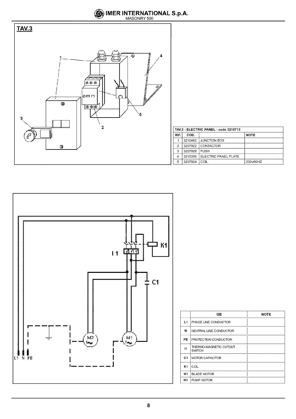
GB NOTE
LI PHASE LINE CONDUCTOR
N NEUTRAL LINE CONDUCTOR
PE PROTECTION CONDUCTOR
II THERMO-MAGNETIC CUTOUT
SWITCH
Cl MOTOR CAPACITOR
KI COIL
Ml BLADEMOTOR
M2 PUMPMOTOR
TAV.3
ç4jIMER INTERNATIONAL S.p.A.
MASONRY500
I
/
2 TAV.3
-ELECTRICPANEL-code3210713
RIR COD. NOTE
1 3210462 JUNCTIONBOX
2 3207922 CONTACTOR
3 3207928 PUSH
4 3210356 ELECTRICPANELPLATE
5 3207924 COIL 230v/60H7
is
II
Cl
r-I--I
I I
I
IA N FE
I- r
I I
I———— ——I
PDF compression, OCR, web-optimization with CVISION's PdfCompressor

ç4jIMER INTERNATIONAL S.p.A.
MASONRY500
TAV.4
-MACHINESTRUCTURE
UxiSZ
9
TAV.4-MACHINESTRUCTURE
RIF. COD. GB
3215356 ELECTRIC PANEL PLATE
92 3210530 CUTTING WHEELLH GUARD
48 2224145 WAUHER UxIR Z
NOTE
RIF. COD. GB NOTE
I 3258421 CARRIAGE
2 3215577 SINGLE-PHASECOVER
3 2222550 EOLT 5831 M0X20
4 3254945 REARING E0R-2RS1
5 2223923 SELELOCKINGNUT M.5
U 3257397 WHEEL
7 2222090 ROLT 9737V8x75
U 3216311 GUOE RAN
9 3208442 LEETPENCE
ADHESIVE
16 3208441 RICHTPENCEAOHEUVE
11 3200501 RUBBERCOAITING
12 3210402 WASHER
13 2265675 SHOCKARSORRER
14 3210342 PEDALPIPE
15 3210560 CUTTING HEAD
GROUP
16 3210407 SUPPORT
17 2223929 SELPLOCKINGNUT V10
18 3206965 PLUG
19 2222567 SCREW 5933VSS2U
20 2218406 SPRAYGUARD
21 3210249 PRAME
22 2216270 ADJUSTING ROD PIPE.
23 3210337 KNOB
24 0329 DRUM
25 35428 PLUG
26 6712 WATERPUMP 23SVWSHZ
27 27320 OILSEALRING
28 3 0313 SCREW
29 3 8571 SHAPT
30 3186 NYLONBUSHRG
31 22002 SCREW 0738M6x16
32 2059 SCREW 5739M8X25ZOX.
33 8414 LEVER
34 8422 ONIDMETER
35 7213 IDEEARSUPPORT
36 3208428 TROLLEYSLIDE
37 3210236 GUIDEBARSUPPORTSX
38 2222568 SCREW M4X20Z
W 21 23 03 6 CUTTING WHEELCASING
ADJUSTMENT
48 3209333 KNOB MU
41 3208426 TROLLEYCLAMPING
42 2224536 WASHER
43 2223288 SCREW
44 3209332 CAM
45 2222818 SCREW M4
47
45 3210713 JUNCTION BOX 23SVWOHZ
49 2285585 HANDGRIP
55 3205013 REARING 62002R5
51 3210301 DRCCOVER
52 3232759 OILSEALRING 3NX52X7
53 3204777 INNER PLANGE
54 3204776 OUTER FLANGE
55 3210317 WATERHOSE
56 3210629 REARING 60062R5
57 2218075 VALVE
58 3210322 BLADECOVER
68 3215189 SELPLOCKINGNUT M.28
61 3210572 PULLEY
62 2204655 SUPPORT
64 3210346 PLUG 155x55x3
65 3215278 BLADEGUARDROTATION ROD
66 3215315 SPRING DE56.5
67 3210316 CALLIPERPLATE.
68 3210325 CALLIPERPIN
69 3210319 SPRAYGUARD
78 3210353 TIEROD SCREW IOXUO
73 3210412 FILTERPIPE
74 2228780 SNAP-PIN
75 1222694 SCREW MIS X11S
76 3210345 PULLEY 85X45X3
77 3210323 PULCRUM PIN
78 3210324 PEDALPIN
79 3210483 LOCKING PIPE
85 1224323 WASHER
81 2209400 NYLON RUSHING 3SAP.
82 2228700 SPLITPIN
83 3208329 SPACERRRACKET
85 3210411 SPACERBRACKET
86 2222130 BOLT M16055
97 2223506 NUT D.1U
58 2223650 NUT 0.10
69 2257785 PULLEY
98 3210532 GASKET
91 3210531 CUTTING WHEELRHGUARD
46 2224148 WASHER
PDF compression, OCR, web-optimization with CVISION's PdfCompressor
ONEYEARWARRANTY
Wewarrant totheoriginal purchaser thatthe IMER equipment described herein
(the"equipment") shall befreefrom defectsin material and workmanship under
normaluseandserviceforwhichitwasintendedforaperiod ofone(1)year
from
thedateofpurchaseby
theoriginalpurchaser.
Ourobbligationunderthiswarrantyis
expressely limitedtoreplacingorrepairing,
freeof charge, F.O.B.our designated service facility, such part orparts ofthe
equipmentasourinspectionshalldisclosetobedefective.Partssuchasengines,
motors, pumps,valves,
electricmotors,etc.furnished
byusbutnotmanifactured
by
uswillcarryonly
thewarrantyofthemanifacturer.
Transportationchargesorduties
shallbebornebythepurchaser.
Thisshallbethelimitofour
liabilitywith respect
to
thequalityoftheequipment.
This
warranty
shallnotapplytoanyequipment, orpartsthereof,whichhas been
damaged byreasonofaccident, negligence, unreasonableuse,faultyrepairs, or
which has not been mantained and operated in accordance with our printed
instructionsforour
equipment.Further,
thiswarrantyisvoidiftheequipment,
or
any
ofitscomponents,isalteredormodified inanyway.
THIS WARRANTY IS EXPRESSLY IN LIEU OF ALL OTHER WARRANTIES,
EXPRESSEDOR IMPLIED, INCLUDINGANY IMPLIED WARRANTYOF
MERCHANTABILITYOFFITNESSFORAPARTICULARPURPOSE.
Wemake noother
warranty,representation
or
guarantee,norisanyone
authorized
tomakeoneonourbehalf.Weshall notbeliablefor
anyconsequentialdamageof
anykind, including loss or
damage resulting,directly
orindirectly,
fromtheuseor
loss ofuseofthe machine. Without limiting the generality oftheforegoing, this
exclusionfrom
liabilityembracesthepurchase'sexpenses
for
downtime,damages
forwhichthepurchaser maybeliabletoother
persons,damages toproperty,
and
injury
ordeathof
anypersons.
This
warranty
shallnotbedeemed tocover maintenance parts,including butnot
limitedto blades,belts, hoses, hydraulic oil or
filters, forwhichweshall have no
responsabilityor
liabilitywhatsoever.
IMERU.S.A.,Inc.
207LawrenceAvenue
SouthSan Fancisco, California94080
(650)872-2200
PDF compression, OCR, web-optimization with CVISION's PdfCompressor
Other manuals for MASONRY 500
2
This manual suits for next models
1
Table of contents
Other IMER Saw manuals


