Hilti DS-WSS 30 User manual

Operating instructions en
DS-WSS 30
Printed: 08.07.2013 | Doc-Nr: PUB / 5069762 / 000 / 01

2
ORIGINAL OPERATING INSTRUCTIONS
Contents
General information 3
1. General description and technical data for the DS-WSS 30 wire saw 4
2. General warnings 6
3. Warnings and safety precautions for the DS-WSS 30 wire saw 7
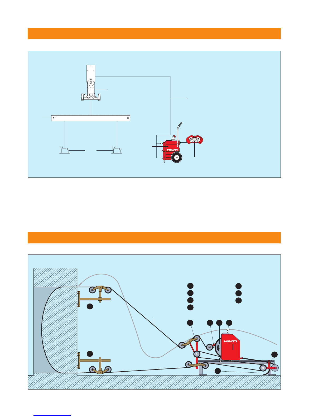
4. D-LP 32 (30) / DS-TS 32 (30) modular saw system 10
5. D-LP 32 (30) / DS-TS 32 (30) / DS-WSS 30 modular wire saw system 10
6. Setting up the wire saw system 11
7. Basic applications 14
8. Diamond wire store 19
9. Instructions for connecting Hilti DS-W 10.5 diamond wire 20
10. DS-WSS 30 wire saw system - checks, operation, and sawing procedure 24
11. Care and maintenance 27
12. Troubleshooting 28
13. Disposal of the DS-WSS 30 / D-LP 32 wire saw 32
14. Manufacturer's warranty – tools 33
15. EC declaration of conformity (original) 34
Congratulations!
On purchasing the Hilti DS-WSS 30 wire saw as an addition to the D-LP 32 (30) / DS-TS 32 (30) wall saw system, you
have acquired a quality product that provides the highest level of performance, safety and reliability. Uncompromising
quality assurance during its manufacture ensures that the system will have a long service life.
This manual describes the operating procedures for the DS-WSS30 only. The saw system functions only in conjunc-
tion with the Hilti D-LP 32 hydraulic power unit. Please refer to the D-LP 32 / DS-TS 32 operating instructions for infor-
mation about operation of the power unit.
These operating instructions are intended for the use of concrete cutting service contractors and their experienced per-
sonnel, referred to on the following pages as “the operator”. Before operating the Hilti D-LP 32 (30) / DS-TS 32 (30) /
DS-WSS 30 wire saw system, the operator must read and understand these operating instructions and receive train-
ing from a Hilti specialist.
Thanks to its modular design, the DS-WSS 30 wire saw system can be quickly and easily fitted to the standard saw
system. Its new design concept, offering maximum convenience and safety in use, opens up an almost endless range
of applications in demolition, cutting and remedial work in steel reinforced concrete, masonry and stone. The variable
oil flow rate of the D-LP 32 (30) / DS-TS 32 (30) wall saw system used to power the wire saw ensures smooth, gentle
starting, and automatic regulation of the wire sawing process and greatly reduces strain on the operator.
This system therefore provides the prerequisites for efficient, economical and safe operation. We would like to wish you
every success in your work and thank you for placing your confidence in Hilti products.
Printed: 08.07.2013 | Doc-Nr: PUB / 5069762 / 000 / 01

3
G n ral information
Th op rating instructions must b r ad car fully
b for th quipm nt is put into op ration.
Always k p th s op rating instructions with th
quipm nt.
Th wir saw syst m should b hand d ov r to
oth r p rsons only compl t with th op rating
instructions.
Safety otices a d their mea i g
DANGER
Draws attention to imminent danger that will lead to
serious bodily injury or fatality.
WARNING
Draws attention to a potentially dangerous situation
that could lead to serious personal injury or fatality.
CAUTION
Draws attention to a potentially dangerous situation
that could lead to slight personal injury or damage to
the equipment or other property.
NOTE
Draws attention to an instruction or other useful infor-
mation.
Explanation of th pictograms and oth r information
General warning Warning:
electricity
Warning:
avoid hand injuries
Wear protective gloves.
Wear safety footwear. Wear respiratory
protection.
Wear ear protection.
Wear eye protection. Wear a hard hat.
Warning signs
Obligation signs
Warning:
Risk of cutting injury
Return waste
material for
recycling.
Read the operating
instructions before use.
Symbols
A
Amps
V
Volts Alternating current
∅∅
Diameter
W
Watts
Hz
Hertz
no
Nominal speed
under no load
mm
Millimeters
/min
Revolutions per minute
rpm
Revolutions per minute
STOP
Stop
Printed: 08.07.2013 | Doc-Nr: PUB / 5069762 / 000 / 01

4
1.2 Single-pair pulley stand
Fastening spindle/nut for rail support or pulley stand
DS-WSSP single-pair pulley stand
Water supply to kerf
DS-WSW 200 guide pulley
DS-WSW 500 drive wheel
DS-WSTA tensioning arm
DS-WSWD wire distributor
DS-WSRP wire length adjustment pulley
DS-WSRF rail support (2×)
Drive wheel guard
Diamond wire guard
DS-WSWS water supply
D-LP 32 (30) power unit
1.1 System
1.2
1. G n ral d scription and t chnical data for th DS-WSS 30 wir saw
Printed: 08.07.2013 | Doc-Nr: PUB / 5069762 / 000 / 01

5
1. G n ral d scription and t chnical data for th DS-WSS 30 wir saw
1.3 Technical data
DS-DS 30
Drive wheel: 500 mm dia.
Guide pulley: 200 mm dia.
Speed (DS-TS 30, 1st gear): 800 r.p.m.
Cutting speed: approx. 20 m / sec.
Wire store capacity: 8 m diamond wire
Max. diamond wire length: 30 m
D-LP 32 hydraulic power unit
Rated power input at 63A 43 kW
Rated output 32 kW
Rated voltage 400 V / ~ 50 Hz, 3P+N+PE or 3P+PE
Ground fault circuit breaker (30 mA) in mains supply on site
Max. operating pressure 210 bar
Oil flow rate 30–100 l/min
Dimensions (L×W×H) 790×540×1090 mm
Weight 220 kg
IP protection code IP 44
Water cooling with 7 l/min. at max. 6 bar and water temperature 20°C
D-RC-LP32 remote control unit
Control voltage 24 V = (direct current)
Dimensions (L×W×H) 390×180×120 mm
Weight 2.2 kg
IP protection code IP 65
Cable length 10 m
Cable length with extension 20 m
Noise information (measured in accordance with EN 15027)
Wear ear protection!
Mean A-weighted sound power level LwA 105 dB (A)
Mean A-weighted emission sound pressure level at the workplace LpA 85 dB (A)
Uncertainty for the stated sound level: 3 dB (A)
1.4 Special accessories
Special stand with 140 mm dia. plunging pulley
Release pulley
Printed: 08.07.2013 | Doc-Nr: PUB / 5069762 / 000 / 01

6
2. G n ral warnings
2.1 Don’t attempt to use the hydraulic saw system and DS-WSS 30 wire saw accessory modules without having
received the appropriate training from an authorised Hilti specialist.
2.2 Always use the hydraulic saw system in accordance with the wall saw operating instructions and supplementary
wire saw system operating instructions. The operating instructions must always be kept at hand. The instructions
on anchoring and securing the system must be observed.
2.3 Approval must be obtained from the site engineer or site management before sawing. Sawing work can negatively
affect the stability of a building or other structure, particularly when reinforcing bars or supporting members are
cut through. Ensure that there are no concealed gas, water, electricity or other supply lines in the area in which
sawing work is to be carried out.
2.4 The area in front of, behind or below the surface where sawing work or drilling is to be carried out must be secured
in such a way that persons or equipment cannot be injured or damaged by falling blocks of concrete or by con-
crete slurry. Where necessary, cores or blocks of concrete should be secured to prevent them from falling.
2.5 Operators and all other persons must stay clear of the area when a load is being lifted by a crane.
2.6 Concrete blocks with a weight of several tons may be sawn out with the Hilti saw. Measures for securing and
transporting these concrete blocks must be planned and implemented. Make use of the steel wedges contained
in the set of tools for securing concrete blocks. eep the working area clean and tidy and cordon off openings.
2.7 National regulations and laws as well as the operating instructions and the safety information applicable to
the accessories employed must be observed.
2.8 The D-LP 32 (30) / DS-TS 32 (30) / DS-WSS 30 saw system must NOT be operated in environments where a risk
of explosion exists unless special safety precautions are taken.
Printed: 08.07.2013 | Doc-Nr: PUB / 5069762 / 000 / 01

7
3.1 Make sure sufficient space is available for working safely. If possible, the wire saw should be set up on the floor
in an upright position.
3.2 Check the entire system, accessories, power unit, electric cables, hydraulic hoses and accessories for damage and
proper functioning before use. Wearing parts, accessories and safety-relevant devices, such as the diamond wire
drive wheel, return pulleys, diamond wire and couplings, diamond wire guard and drive wheel guard, end stop,
drive wheel mounting screw, hydraulic couplings, etc., must be checked particularly carefully. Check that all parts
have been assembled correctly and consider all other factors that could influence operation of the equipment.
Contact your Hilti representative or Hilti service centre if faults or deficiencies are found. Repairs to electrical parts
must be carried out by a qualified electrical specialist.
3.3 Metal anchors of M12 size should be used for fastening the DS-WSRF rail support and DS-WSSPP single-pair pul-
ley stand. The fastening used must be suitable for the base material in question and must not work loose. Suitable
Hilti anchors are, e.g. H D-D, HSA-A, HIT or HEA. If masonry is loose or crumbling, we recommend that through
holes are drilled and M16 threaded rods with clamping nuts used for fastening.
3.4 Fastening screws of at least 8.8 grade as per ISO should be used for the rail supports or, alternatively, use the
DD-CS M12 S-SM clamping spindle with DD-CN-SML quick-release clamping nut.
3.5 An end stop must always be fitted at the end of the rail to prevent unintentional advance beyond this point (pre-
vents the saw head coming off the end of the rail).
3.6 It is essential that the specified checks are carried out before sawing.
3.7 The drive wheel guard (see fig. 3.7, no. 1) and diamond wire guard (see fig. 3.7, no. 2) MUST ALWAYS BE FITTED
when the saw is in use. These guards prevent parts flying out in the direction of tension should the diamond wire
break. NEVER stand in a position in line with the diamond wire while the saw is running.
12
2
1
3.7
3. Warnings and saf ty pr cautions for th DS-WSS 30 wir saw
3.8 ■Safety measures must be implemented in the area where sawing is taking place so that operators and
bystanders cannot be injured or property damaged by a broken sawing wire or debris that may fly off
during the sawing operation (wire connectors diamond beads spacing springs small stones saw-
ing slurry etc.). Safety measures must also be implemented in the area not directly visible to the oper-
ator i.e. behind where sawing is taking place.
Printed: 08.07.2013 | Doc-Nr: PUB / 5069762 / 000 / 01

8
■Persons must NEVER enter the danger area while sawing is in progress.
■Always keep the free wire lengths between the drive unit and object being cut as short as possible
(max. 3.5 m) and mount guide pulleys at the wire entry and exit points in order to reduce the risk of
whiplash in the event of wire breakage. The whiplash effect causes great acceleration of the sawing
wire resulting in parts of the wire lashing out or flying off with great force.
■Make sure there are no objects such as scaffolding etc. within the wire whiplash area. In the event of
wire breakage the whiplashing end of the wire may be deflected in an unexpected direction by such
objects.
■The danger area has a radius of at least twice the free length of wire that would be unleashed in the
event of wire breakage (shown in yellow) and also includes the areas in the extended axes of the direc-
tion in which the wire is running (shown in gray). The danger area cannot be limited unless suitable
means of protection are employed (protective walls curtains or wire guards etc.). The protective
devices must be arranged and mounted in a way that stops the wire lashing out in the event of wire
breakage and reliably prevents objects or fragments flying off.
■The operator is responsible for cordoning off the area. If necessary safety personnel must be posted
to prevent access to a wide area around the workplace
■When setting up and operating the saw system and when removing parts that have been cut away
always ensure that no persons are below the area in which you are working. Falling objects could
cause serious injury.
■Children must be instructed not to play with the machine.
■The machine is not intended for use by children by debilitated persons or those who have received
no instruction or training.
■Before begi i g work, check the worki g area (e.g. with a metal detector) to e sure that o co -
cealed electric cables or gas a d water pipes are prese t.
External metal parts of the machine may become live if for example an electric cable is damaged
inadvertently. This presents a serious risk of electric shock.
3.9 ALWAYS SWITCH OFF THE WIRE SAW BEFORE ADJUSTING THE WATER SUPPLY. Readjustment of the water sup-
ply nozzle at the single-pair pulley stand or at any other position while the saw is running, in order to bring it into
line with the diamond wire, is STRICTLY PROHIBITED.
3.10 The wire length adjusting pulley (DS-WSRP wire store) must always be fitted, even when not in use. The flexible
wire guard can then be fitted in accordance with the instructions.
276377 05.06
r2=l2x 2
l2
l1
r1=l1x2
3.8
3. Warnings and saf ty pr cautions for th DS-WSS 30 wir saw
Printed: 08.07.2013 | Doc-Nr: PUB / 5069762 / 000 / 01

9
3. Warnings and saf ty pr cautions for th DS-WSS 30 wir saw
3.11 Never connect or disconnect hydraulic hoses while the power unit is running or while the hoses are under pressure.
3.12 Wear suitable clothing. Don’t wear loose clothing or jewellery which could become caught in moving parts of the
machinery. Wear a hard had, protective goggles, protective gloves, safety shoes, ear protectors and a hairnet if
you have long hair. A face mask should be worn to protect the respiratory system when working in enclosed areas.
3.13 Avoid body positions in which the back is bent when carrying motor units or other heavy components. Maintain
a secure stance and always stay in balance, especially when using ladders or when working from scaffolding.
3.14 Check all screws on the DS-TS 32 (30) saw, tensioning arm, diamond wire guard and drive wheel guard which
could work loose due to vibration.
3.15 Disconnect the electric extension cable from the mains supply when the equipment is not in use, during trans-
port and before inspection or maintenance. Ensure that the hydraulic power unit is switched off before changing
the diamond wire or before adjusting the position of the guide pulleys. As an additional safety measure, it is rec-
ommended that the EMERGENCY STOP button is pressed and left in the OFF position.
3.16 Use of the Hilti diamond wire saw system is permitted only in conjunction with the other DS-WSS 30 components
listed in these instructions. The use of individual components for wire sawing, e.g. only the drive wheel, is pro-
hibited as this could present a serious hazard to the operating personnel.
3.17 For further information, please refer to the D-LP 32 (30) / DS-TS 32 (30) operating instructions.
Printed: 08.07.2013 | Doc-Nr: PUB / 5069762 / 000 / 01

10
4. D-LP 32 (30) / DS-TS 32 (30) modular saw syst m
5. D-LP 32 (30) / DS-TS 32 (30) / DS-WSS 30 modular wir saw syst m
DS-R 230L
DS-TS32
DS-RF
D-PH34-10 (2x)
D-FH4/14-10
DS-RF
D-LP 32
D-RC-LP 32
comprising:
1 D-LP 32 (30)
2D-RC- LP 32 (DS-CB)
3D-PH34-10 (2x)
4D-FH4/14-10
5DS-RF
6DS-R230L
7DS-TS32 (30)
1
6
5
3/
4
7
2
2x DS-WS-SPP
7
DS-WSWS
6
2x DS-WSRF
5
DS-WSRP
4
DS-WSWD
3
DS-WSTA
2
DS-WSW500
1
DS-W10.5
7
6
5
74
123
DS-WSS30 comprising:
Printed: 08.07.2013 | Doc-Nr: PUB / 5069762 / 000 / 01

11
6. S tting up th wir saw syst m
6.1 Through-holes for the diamond wire
– Plan the working procedure carefully and precisely before beginning to install the system and before drilling the
through-holes.
– Drill the through-holes for the diamond wire (see fig. 6.1, no. ).
Use a suitable drilling machine, depending on the situation and the base material:
킞Combihammer TE 70 with 16 mm dia. drill bit
킞Diamond drilling machine DD 200 with the core bit DD-BS 52
6.2 Fastening to the base material
WARNING
Use a a chor suitable for the material o which you are worki g a d observe the a chor ma ufactu-
rer’s i structio s.
NOTE
Hilti M12 metal expa sio a chors are usually suitable for faste i g diamo d core drilli g equipme t
to u cracked co crete. U der certai co ditio s it may be ecessary to use a alter ative faste i g
method. Please co tact Hilti Tech ical Service if you have a y questio s about secure faste i g.
– Rigid and secure fastenings are the basic prerequisite for efficient and safe sawing. We recommend the use of
Hilti drilling and anchoring systems.
– Fasteners suitable for the base material in question should be used to fasten the rail supports and single-pair
pulley stands. For example, a minimum edge distance of 18 cm must be observed when setting the Hilti H D
M12 metal expansion anchor. As a general rule, this anchor should be set ≥ 5 mm below the surface of the con-
crete. After drilling the hole, the dust should be blown out.
– Hilti HIT adhesive anchors can be used in masonry etc. or, alternatively, through-holes drilled and threaded rods
used.
6.3 Recommended fastening method using the clamping spindle and clamping nut
For fastening the rail supports and single-pair pulley stands, Hilti recommends use of the H D-D anchor in con-
junction with the double-thread clamping spindle and clamping nut with pivoting baseplate.
Advantages
1. Flexible clamping nut / baseplate provides secure fastening even on uneven surfaces and when anchor holes
are drilled at an angle.
2. Coarse thread pitch for rapid assembly and disassembly
3. The anchor can be set deeper.
6.1 6.2
Clamping nut with pivoting baseplate
Double-thread clamping spindle
Through-hole for the diamond wire
Printed: 08.07.2013 | Doc-Nr: PUB / 5069762 / 000 / 01

12
Acc ssori s for fast ning th wir saw and pull y stands
Description Use Package Ordering designation Item no.
contents
Combihamm r Drilling anchor holes 1TE70 000000
Hamm r drill bit Drilling anchor holes 1TE-YX-16/35 333760
Blow-out bulb Cleaning anchor holes 1BB 059725
Flush anchor Fastening the wire saw / pulley stands 50 HKD-D M12x50 252961
Manual s tting tool Expanding the anchors 1HSD-G M12x50 243743
Clamping spindl Fastening the wire saw / pulley stands 1DD-CS M12 S-SM 251830
Clamping nut Fastening the wire saw / pulley stands 1DD-CN-SML 251834
Acc ssori s for drilling through hol s
Description Use Package Ordering designation Item no.
contents
Combihamm r Drilling through holes 1TE 70 000000
Hamm r drill bit Drilling through holes 1TE-YX 16/55 333761
Hamm r drill bit Drilling through holes 1TE-YX 16/92 370564
Point d chis l Rounding edges of holes 1TE-YP-SM28 282263
Diamond coring machin Drilling through holes 1DD 200 000000
Diamond cor bit Drilling through holes 1DD BS52/430 000000
Ext nsion Drilling through holes 111/4" UNC 009850
Diamond coring is recommended for corner holes in very thick walls in heavily reinforced concrete and where very precise
cuts must be made.
6.4 Recommended fastening set
Advantages
■Can be set deeper: special H D-D anchor without collar
■High holding power: H D-D M12 metal expansion anchor with 16 mm outside diameter
■Flexible clamping nut / baseplate for secure fastening even when anchor holes are drilled at an angle or on
uneven surfaces
■Coarse thread pitch for rapid assembly and disassembly
■Avoids damage to the baseplate or rail support
6. S tting up th wir saw syst m
Printed: 08.07.2013 | Doc-Nr: PUB / 5069762 / 000 / 01

13
6. S tting up th wir saw syst m
DSW-WG wir guards
(It m no. 365426)
Wire guards must be fitted in situations where it can-
not be ensured that persons do not enter the area in
which flying objects present a risk of injury while the
equipment is in operation or where there is a risk of
damage to property or other equipment within this
area. When wire guards are used check to ensure
they are fitted correctly.
DS-WS-SPP singl -pair pull y stand
(It m no. 365427)
In applications where due to restricted access it is
impossible to mount the compact wire saw directly on
the object to be cut or where longer cuts of up to a
maximum of 2 meters are to be made the sawing wire
is guided to the cutting face by the pulley stand.
DS-WSRW r l as pull y
(It m no. 315834
)
The release pulley is used to reduce the length of wire
in contact or to increase the radius of the arc followed
by the wire (avoiding a tight radius) at the rear of the
object to be cut.
DSW-PW plung wh l
(It m no. 365428)
For plunge applications of all kinds. At least 2 are
required. Can also be mounted on the single-pair pul-
ley stand if necessary.
DS-WSS 30 guard
(It m no. 276388)
DS-WSS 30 guard
(It m no. 276379)
Printed: 08.07.2013 | Doc-Nr: PUB / 5069762 / 000 / 01

14
7.1 Standard vertical cut
– Optimum cutting length
– No tight diamond wire radius in the
concrete
– Average cutting performance
– Normal rate of wire wear
7.2 Vertical cut with release
pulley
1ststep
– Relatively short cutting / contact
length
– High cutting performance
– High rate of wire wear
Note
When the kerf is at the height of
pulley , the pulley should be
turned and positioned below the
wire.
2nd step
Note
At the end of the cut, when the dia-
mond wire is pulled out of the kerf, it
is caught by pulleys and .
– No danger of the wire lashing
back
– Avoids damage to the wire
Note
The optimum cutting length for the Hilti DS-WSS 30 wire saw system is 1 to 4.5 metres, i.e the diamond wire is
in contact with the workpiece over a length of 1 to 4.5 metres.
12
12
1
2
Water
Water
Water
Water
WaterRelease pulley
Diamond wire
Tension side
Diamond wire
Tension side
Diamond wire
Tension side
Release pulley
7. Basic applications
Printed: 08.07.2013 | Doc-Nr: PUB / 5069762 / 000 / 01

15
7.3 Standard horizontal cut
7.4 Flush horizontal cut
AAt the beginning of the cut
Wall saw
Pivoting pulley
with ball-bearing
pivot
Pivoting pulley
with ball-bearing
pivot
7. Basic applications
Printed: 08.07.2013 | Doc-Nr: PUB / 5069762 / 000 / 01

16
Note
In order to prevent the diamond wire from jumping off the pivoting guide pulleys, we recommend that the wire saw
is switched off shortly before completing the cut and that a combihammer is used to break away the small amount
of remaining material.
BAt the end of the cut
Pivoting pulley
with ball-bearing
pivot
Pivoting pulley
with ball-bearing
pivot
Side view
Diamond wire
Pivoting pulley
Saw kerf
7. Basic applications
Printed: 08.07.2013 | Doc-Nr: PUB / 5069762 / 000 / 01

17
7.6 Flush cutting
– For flush cutting, the pulleys
with ball-bearing pivot must
always be used. These pulleys
are designed to pivot easily
and follow the movement of
the diamond wire. They can be
easily differentiated from the
type with plain bearings (see
fig. 10.3).
– The pulleys with ball-bearing
pivot should always be posi-
tioned at the points where the
diamond wire enters or leaves
the concrete.
7.5 Aligning the guide pulleys
As a general rule, all guide pulleys must be aligned with each other so that the diamond wire always runs in the
middle of the pulley (minimises pulley wear and reduces the risk of the diamond wire jumping off).
Exception
Two guide pulleys on the slack
side, between the wire distribu-
tor pulleys and the pulley stand
at the point the diamond wire
enters the concrete, should be
set up at a slight angle (see fig.
7.5). This assists the diamond
wire to rotate about its own axis
while cutting, thereby achieving
more even wear.
12
Water
Water
Diamond wire
Tension side
7.5
Slack side
7. Basic applications
Pulley with
ball-bearing pivot
Pulley with
ball-bearing pivot
Diamond wire
Clamping screw
Ball bearing
Pivoting pulley
erf
Plain bearing
Can be clamped
in position
Clamping screw
Loosen screw
for flush cutting
7.6
Printed: 08.07.2013 | Doc-Nr: PUB / 5069762 / 000 / 01

18
7.7 Wire saw application using plunging pulleys
Note
When cutting over a length of 2–3 m, the plunging pulleys must always be positioned 20 to 30 cm below the
desired depth as a slight curve always remains at the end of the cut.
7.7a
7.7c
7.7b
Special stands
Pivoting plunging pulleys
140 mm dia.
Radius at end of cut
20–30 cm
Desired
depth of cut
Tubular
extension
2″dia.
Tubular
extension
2″dia.
Length of cut
Pivoting pulleys (to saw head)
200 mm dia.
Hole
162 mm dia.
Pivoting plunging pulleys
140 mm dia.
Radius at end of cut
20–30 cm
Tubular
extension
2″dia.
Tubular
extension
2″dia.
Length of cut
Pivoting pulleys (to saw head)
200 mm dia.
Hole
∅162 mm
20–30 cm
Radius at end of cut
Length of cut
Tubular
extension
2″dia.
Tubular
extension
2″dia.
Pivoting plunging pulleys
140 mm dia.
Pivoting pulleys (to saw head)
200 mm dia.
7. Basic applications
7.7d
Printed: 08.07.2013 | Doc-Nr: PUB / 5069762 / 000 / 01

19
The built-in return pulley and wire store pulley can be used to reduce the effective length of the diamond wire by up
to 8 m with a rail length of only 2 m (DS-R 200 L).
Important
No matter how the wire saw is set up, the DS-WSRP wire length adjusting pulley must always be fitted and the
diamond wire guard belonging to it attached at the bottom of the drive wheel guard.
Configuration 1
Configuration 2
Configuration 3
Configuration 4
2×1.5 m
2×0.5 m
2×0.5 m
2×1.5 m
= 3 m
+
+
+
= 1 m
= 1 m
= 3 m Total 8 m
Drive wheel guard End stop
Diamond wire guard
Wire length adjusting pulley
2 m rail (DS-R200L)
8.Diamond wir stor
Printed: 08.07.2013 | Doc-Nr: PUB / 5069762 / 000 / 01

20
Cutting dir ction
Important: The connectors must be fitted relative to the cutting direction as shown in the illustration. The
diamond wire must be used to cut in one direction only (see arrows).
Pr parations for th first cut
■Connectors are already fitted to new diamond wires.
■The diamond wire must be twisted before joining the connectors by inserting the pin. Twist the diamond wire
approx. 1–1.5 turns per metre length of wire in a counter-clockwise direction (to the left) as seen when look-
ing straight at the cut face of the end of the wire.
■The corners on the workpiece should be rounded off to a radius of approx. 10 cm (using a hammer and chis-
el or a Hilti combihammer) and/or the diamond wire pulled through by hand.
■Mount the water supply nozzle at the point where the wire enters the workpiece. Depending on the length of
the cut it may be necessary to apply cooling water at several points. It is essential that the wire is cooled
perfectly if good cutting results are to be achieved.
■Use the advance movement to tighten the wire. Move away from the machine to a safe distance and start the
motor. Start the saw gently and then increase the running speed gradually until the optimum drive speed
(r.p.m.) and cutting speed is reached.
■The sawing operation must be monitored continuously.
■The wire saw must be stopped before making adjustments to the water supply nozzles.
G n ral information
■Do not kink or bend the wire sharply.
■Do not join diamond wires of different diameters together.
■To ensure even wear of the beads the diamond wire must be retwisted after each long cut applying a dif-
ferent number of turns before beginning the next cut.
9. Instructions for conn cting Hilti DS-W 10.5 diamond wir
Printed: 08.07.2013 | Doc-Nr: PUB / 5069762 / 000 / 01
Table of contents
Other Hilti Saw manuals

Hilti
Hilti DSW 1510-CA User manual

Hilti
Hilti WSC 85 User manual

Hilti
Hilti DSH 600 User manual

Hilti
Hilti SCW 22-A User manual

Hilti
Hilti DSH 700-X User manual

Hilti
Hilti NURON SR 6-22 User manual

Hilti
Hilti DST 10-CA User manual

Hilti
Hilti SR 6-A22 User manual

Hilti
Hilti SCM 22-A User manual

Hilti
Hilti SR 6-A22 User manual

Hilti
Hilti DSH 700-X User manual

Hilti
Hilti Nuron DSH 600-22 User manual

Hilti
Hilti DSF 1030-TS User manual

Hilti
Hilti SCM 22-A User manual

Hilti
Hilti SB 4-A22 User manual

Hilti
Hilti SR 30-A36 User manual

Hilti
Hilti D-LP 30 User manual

Hilti
Hilti SC 55W User manual

Hilti
Hilti SC 60W-A36 User manual

Hilti
Hilti SR 4-A22 User manual