Warranty
Warranty malfunctions occurring under conditions of normal use
in conformity with the Instruction Manual and Product Precau-
tionary Markings will be repaired free of charge. This warranty
is valid for a period of one (1) year from the date of purchase.
Please contact the distributor from which you purchased the
product for further information on warranty provisions.
Introduction
Thank you for purchasing the HIOKI Model 9555-10 SENSOR
UNIT. To obtain maximum performance from the device, please
read this manual first, and keep it handy for future reference.
With this device, you can use the Model 9270, 9271, 9272,
9277, 9278, 9279, 9709, 9272-10, CT6862, CT6863 current
sensors as separate units. It is equipped with a high-perfor-
mance sensor for easy current waveform measurement.
Use it as input unit for various current measurement applica-
tions combined with a recorder, oscilloscope, voltmeter, etc.
Initial Inspection
When you receive the device, inspect it carefully to ensure that
no damage occurred during shipping. In particular, check the
accessories, panel switches, and connectors. If damage is evi-
dent, or if it fails to operate according to the specifications, con-
tact your dealer or Hioki representative.
Maintenance and Service
• To clean the device, wipe it gently with a soft cloth moistened
with water or mild detergent. Never use solvents such as
benzene, alcohol, acetone, ether, ketones, thinners or gaso-
line, as they can deform and discolor the case.
• If the device seems to be malfunctioning, confirm that the
batteries are not discharged, and that the test leads, probes
and fuse are not open circuited before contacting your dealer
or Hioki representative.
This manual contains information and warnings essential for
safe operation of the device and for maintaining it in safe oper-
ating condition. Before using it, be sure to carefully read the fol-
lowing safety precautions.
Safety Symbols
The following symbols in this manual indicate the relative impor-
tance of cautions and warnings.
Other Symbol
Measurement categories
To ensure safe operation of measurement devices, IEC 61010
establishes safety standards for various electrical environ-
ments, categorized as CAT II to CAT IV, and called measure-
ment categories.
CAT II: Primary electrical circuits in equipment connected to an AC
electrical outlet by a power cord (portable tools, household
appliances, etc.)
CAT II covers directly measuring electrical outlet receptacles.
CAT III:Primary electrical circuits of heavy equipment (fixed installa-
tions) connected directly to the distribution panel, and feeders
from the distribution panel to outlets.
CAT IV:The circuit from the service drop to the service entrance, and
to the power meter and primary overcurrent protection device
(distribution panel).
Using a measurement device in an environment designated
with a higher-numbered category than that for which the device
is rated could result in a severe accident, and must be carefully
avoided.
Use of a measurement instrument that is not CAT-rated in CAT
II to CAT IV measurement applications could result in a severe
accident, and must be carefully avoided.
Instrument Installation
Operating temperature and humidity: 0 to 40°C, 80%RH or less (non-condensation)
Follow these precautions to ensure safe operation and to obtain
the full benefits of the various functions.
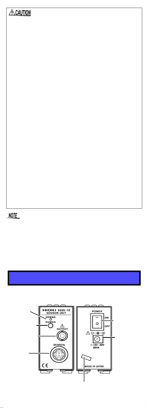
Overview
Inspection and Maintenance
Pack the device so that it will not sustain damage during ship-
ping, and include a description of existing damage. We cannot
accept responsibility for damage incurred during shipping.
Safety
This device is designed to comply with IEC 61010
Safety Standards, and has been thoroughly tested
for safety prior to shipment. However, mishandling
during use could result in injury or death, as well as
damage to the device. Be certain that you under-
stand the instructions and precautions in the man-
ual before use. We disclaim any responsibility for
accidents or injuries not resulting directly from
device defects.
In the manual, the symbol indicates particularly impor-
tant information that the user should read before using the
device.
The symbol printed on the device indicates that the
user should refer to a corresponding topic in the manual
(marked with the symbol) before using the relevant
function.
Indicates DC (Direct Current).
Indicates that incorrect operation presents an extreme
hazard that could result in serious injury or death to the
user.
Indicates that incorrect operation presents a significant
hazard that could result in serious injury or death to the
user.
Indicates that incorrect operation presents a possibility
of injury to the user or damage to the device.
Indicates advisory items related to performance or cor-
rect operation of the device.
Indicates a prohibited action.
Avoid the following locations that could cause an accident or dam-
age to the device.
Exposed to direct
sunlight
Exposed to high temper-
ature
In the presence of
corrosive or explosive
gases
Exposed to water, oil,
other chemicals, or
solvents
Exposed to high humid-
ity or condensation
Exposed to strong
electromagnetic fields
Near electromagnetic
radiators
Exposed to high levels
of particulate dust Subject to vibration
Usage Notes
• Be sure to observe all operating precautions for the
waveform monitoring instrument (oscilloscope or
recorder) and other measurement instruments to
which the CURRENT SENSOR (refer to Specifica-
tions) is connected using with this device.
• When using a measurement instrument that does not
provide isolation between its input terminals and chas-
sis or other input terminals, please pay attention to the
following points.
If a signal is applied to an input terminal other than that
to which the CURRENT SENSOR is connected, do not
connect the ground-side terminal to any non-ground
potential. Otherwise, short-circuit current will flow
through the CURRENT SENSOR or this device from
the ground terminal, which could cause an electrical
accident or damage.
• Before turning the device on, make sure the supply
voltage matches that indicated on the its power con-
nector. Connection to an improper supply voltage may
damage the device and present an electrical hazard.
• Use only the supplied Model 9418-15 AC ADAPTER.
AC adapter input voltage range is 100 to 240 VAC
(with ±10% stability) at 50/60 Hz. To avoid electrical
hazards and damage to the device, do not apply volt-
age outside of this range.