© 2020 HIOKI E.E. CORPORATION A_UG_SP0002E01
This document is accurate as of April of 2020. Content such as specifications may be revised or altered without notice.
If cases 1–3 applies, connecting only the CAN sensor to the CAN bus will cause the LED to indicate
regular operation (flashing green). When “Output Bus Error Detection” is triggered (red and green
alternately flash), first check to see if disconnecting from the device causes the LED to return to
indicating regular operation (flashing green).
■CASE 3: The connected device is sending an error frame
For one reason or another, the connected device could be having trouble properly acquiring a CAN signal. This
can cause the connected device to output an error frame. Below are causes for such a situation.
Cause 1: Incorrect setting of the connected device
The settings for baud rate or sampling point may be incorrect. Especially in the case of CAN FD, an error occurs
when the sampling point settings of the ECU and connected device are not the same.
Cause 2: Acknowledge (ACK) signals are not detected (ACK slot remains 1)
In CAN communication, the node (ECU) that properly receives data sends a dominant (0) during the duration of
the ACK slot of the can frame (see below). When there is only one ECU connected to the CAN bus*, since there
is no ECU that can send “ACK slot = 0”, the connected device may be judging as a signal error and outputting an
error frame. When using this sensor, always connect two or more ECUs to the CAN bus.
*This device does not have the ability to inject a signal. Therefore even if the connected device is set to return
“ACK slot = 0”, the sensor cannot send back an ACK signal to the CAN bus.
Cause 3: There is termination resistance from the connected device
The Non-Contac CAN Sensor’s signal output circuit is equipped with termination resistance of 60 Ω(120 Ω//
120 Ω). If termination resistance exists or is connected to the connected device, the signal level declines causing
the signal to not be properly received by the connected device. When this happens, the connected devices may
send an error frame. If there is termination resistance on the side of the connected device, please remove it. (If
the device has an on/off switch setting for termination resistance, please switch it to “off”.)
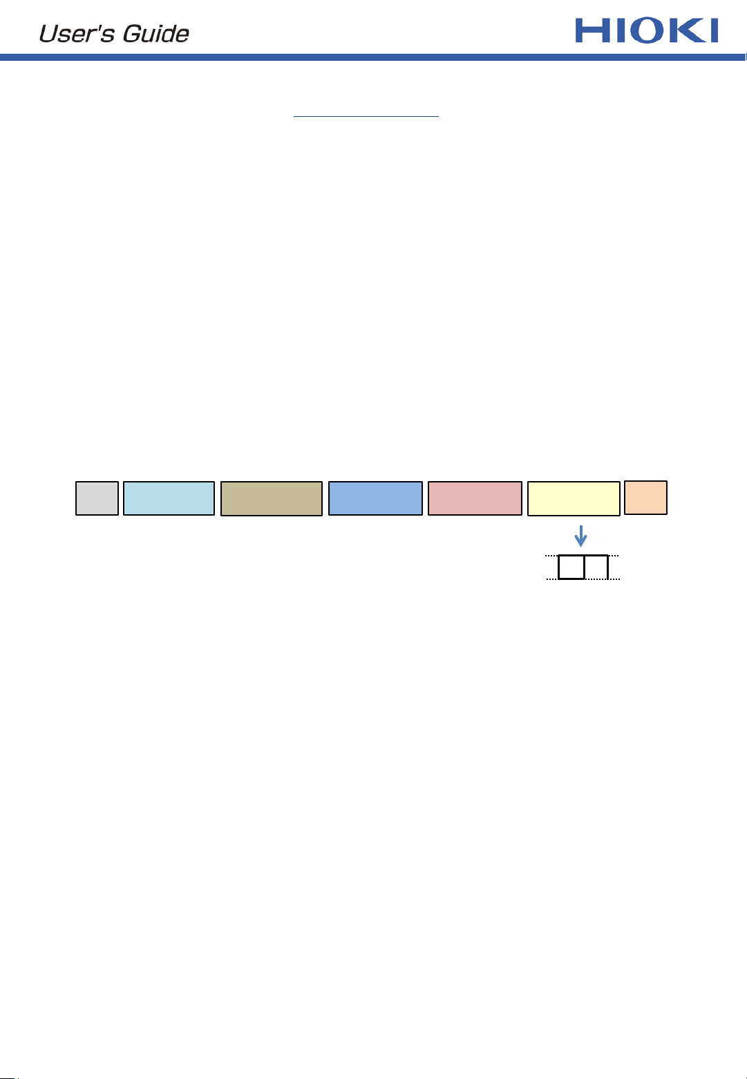
SOF ARB Field CTRL Field Data Field CRC Field ACK Field EOF
SOF・・・Start of Frame
ARB Field・・・include information such as ID
CTRL Field・・・includes identifying information of CAN and CAN FD
Data Field・・・includes data
CRC Field・・・checks whether the sent and received information matches
ACK Field・・・checks if there is at least one node that received without an error
EOF・・・End of Frame
Make-Up of the CAN or CAN FD Frame
ACK delimiter
(1)
→←
ACK slot
(0 or 1)
When “ACK slot = 1”, Collision
between the CAN sensor and
connected device can occur.


