Introduction
Thank you for purchasing the HIOKI Model 9667 Flexible Clamp On
Sensor.
To obtain maximum performance from the product, please read this
manual first, and keep it handy for future reference.
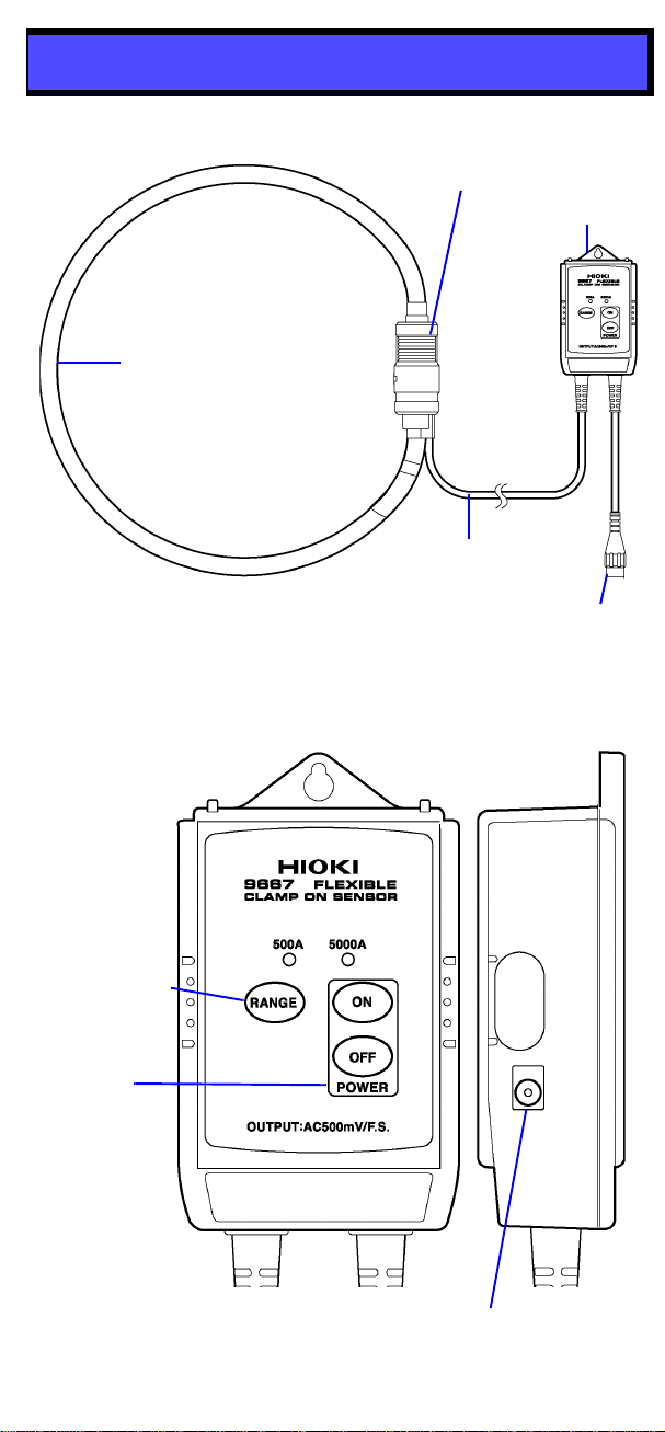
The 9667 Flexible Clamp On Sensor measures large currents of up to
5000 A AC.
The hollow core coil makes the sensor unit highly flexible, allowing it to
be used for clamping in narrow spaces with crowded wiring. This is a
feature not seen in sensors that use conventional cores.
Initial Inspection
When you receive the product, inspect it carefully to ensure that no
damage occurred during shipping. If damage is evident, or if it fails to
operate according to the specifications, contact your dealer or Hioki
representative.
Preliminary Checks
• Before using the product the first time, verify that it operates nor-
mally to ensure that the no damage occurred during storage or ship-
ping. If you find any damage, contact your dealer or Hioki
representative.
• Before using the product, make sure that the insulation on the
cables is undamaged and that no bare conductors are improperly
exposed. Using the product in such conditions could cause an elec-
tric shock, so contact your dealer or Hioki representative for repair.
Maintenance and Service
• To clean the product, wipe it gently with a soft cloth moistened with
water or mild detergent. Never use solvents such as benzene, alco-
hol, acetone, ether, ketones, thinners or gasoline, as they can
deform and discolor the case.
• If the product seems to be malfunctioning, contanct your dealer or
Hioki representative.
(Accuracy guaranteed for one year at 23±5°C (73±9°F), 80%RH or less)
f.s. : maximum display value or scale length (This is usually the maximum value of the
currently selected range.)
rdg.: reading value (The value currently being measured and indicated on the measuring
product)
Follow these precautions to ensure safe operation and to obtain the
full benefits of the various functions.
Measurement categories
This product complies with CATIII (1000 V) safety requirements.
To ensure safe operation of measurement products, IEC 61010 estab-
lishes safety standards for various electrical environments, catego-
rized as CAT II to CAT IV, and called measurement categories.
CAT II: Primary electrical circuits in equipment connected to an AC
electrical outlet by a power cord (portable tools, household appli-
ances, etc.) CAT II covers directly measuring electrical outlet recepta-
cles.
CAT III: Primary electrical circuits of heavy equipment (fixed installa-
tions) connected directly to the distribution panel, and feeders from the
distribution panel to outlets.
CAT IV: The circuit from the service drop to the service entrance, and
to the power meter and primary overcurrent protection device (distri-
bution panel).
Using a measurement product in an environment designated with a
higher-numbered category than that for which the product is rated
could result in a severe accident, and must be carefully avoided.
Use of a measurement instrument that is not CAT-rated in CAT II to
CAT IV measurement applications could result in a severe accident,
and must be carefully avoided.
Safety Symbol
The following symbols in this manual indicate the relative importance
of cautions and warnings.
Indicates that incorrect operation presents an extreme haz-
ard that could result in serious injury or death to the user.
Indicates that incorrect operation presents a significant haz-
ard that could result in serious injury or death to the user.
Indicates that incorrect operation presents a possibility of
injury to the user or damage to the product
Advisory items related to performance or correct operation of
the product.
This manual contains information and warnings essential for safe
operation of the product and for maintaining it in safe operating condi-
tion. Before using the product, be sure to carefully read the following
safety notes.
Accurate measurement may be impossible in the presence of strong
magnetic fields, such as near transformers and high-current conduc-
tors, or in the presence of strong electromagnetic fields such as near
radio transmitters.
Overview
Inspection and Maintenance
Specifications
Rated primary current 5000 to 500 A AC/ 500 to 50 A AC
Output voltage 500 mVAC f.s.
Amplitude accuracy
±
2% rdg.±1.5 mV
(at 45 Hz to 66 Hz, at sensor center)
Frequency band 10 Hz to 20 kHz (amplitude error: within ±3dB)
Phase accuracy Within ±1
°
(at 45 Hz to 66 Hz)
Temperature characteristic
±
2% rdg./°
C
Effect of conductor
position Within ±3% (deviation from center)
Effect of external electro-
magnetic field 5 A equivalent,7.5 A max. (in an external electro-
magnetic field of 400 A/m
Maximum input current 10,000 A continuous (at 45 to 66 Hz)
Dielectric strength 6880 Vrms for 15 seconds (between circuit and sen-
sor, at 50/60 Hz)
Maximum rated voltage to
earth 1000 VACrms or less
Operating temperature
&humidity 0 to 40
°C (32 to 104°F)
, 80%RH or less (non-con-
densating)
Temperature of conductor
to be measured 50
°C or less (122°F or less)
Storage temperature
&humidity -10 to 50
°C (14 to 122°F)
, 80%RH or less (non-con-
densating)
Operating environment Indoors, altitude up to 2000 m (6562-ft.)
Applicable Standards
(Safety) EN61010
Measurement Category III, Pollution
Degree 2
(Anticipated Transient Overvoltage: 8000 V
(EMC)
EN61326
EN61000-3-2
EN61000-3-3
Power supply LR03 alkaline battery x 4 (1.5 VDC x 4) or
9445-02/03 AC ADAPTER (9 VDC) (option)
(Voltage fluctuations of ±10% from the rated supply
voltage are taken into account.)
Maximum rated power
35 mVA (using batteries), 50 mVA (using AC adapter)
Battery life Approx. 7.5 days (continuous)
Output impedance 100
Ω
or less
Measurable conductor
diameter φ254 mm or less
Cable length Approx. 2 m (78.74”) (between sensor and circuit),
approx. 1m (39.37”) (output cord)
Dimensions Approx. 910 mm (35.83”)(when sensor unit is open)
Approx. 57.5W x 86.5H x 30D mm (2.26”W x 3.41”H
x 1.18”D) (Circuit box)
Mass Approx. 450 g (15.9 oz.) (including batteries)
Accessories Instruction Manual, LR03 alkaline battery x 4
Options 9445-02 AC Adapter
9445-03 AC Adapter
Safety
This product is designed to conform to IEC 61010 Safety Stan-
dards, and has been thoroughly tested for safety prior to ship-
ment. However, mishandling during use could result in injury or
death, as well as damage to the product. Using the instrument/
device/ product in a way not described in this manual may
negate the provided safety features.
Be certain that you understand the instructions and precau-
tions in the manual before use. We disclaim any responsibility
for accidents or injuries not resulting directly from product
defects.
In the manual, the symbol indicates particularly impor-
tant information that the user should read before using the
product.
The symbol printed on the product indicates that the
user should refer to a corresponding topic in the manual
(marked with the symbol) before using the relevant
function.
Indicates a double-insulated device.
Indicates AC (Alternating Current).
Indicates DC (Direct Current).
Wear appropriate protective insulation (insulating rubber
gloves and boots, helmet and etc.) when connecting and
disconnecting from live electric circuits.
Usage Notes
• To avoid short circuits and potentially life-threatening
hazards, never attach the product to a circuit that
operates at more than the 1000 V AC, or over bare
conductors.
• This product should only be connected to the sec-
ondary side of a breaker, so the breaker can prevent
an accident if a short circuit occurs. Connections
should never be made to the primary side of a
breaker, because unrestricted current flow could
cause a serious accident if a short circuit occurs.
• To avoid electric shock, do not allow the product to get wet,
and do not use it when your hands are wet.
• To avoid electric shock when measuring live lines, wear
appropriate protective gear, such as insulated rubber gloves,
boots and a safety helmet.
• To avoid electric shock, stop using this product if it shows
either of the following signs of damage, and do not use the
product again until it has been repaired.
1.The blue sensor cover is damaged, and any red part is visi-
ble beneath the cover.
2.The yellow connector cover is damaged, and any black part
is visible beneath the cover.
• Do not store or use the product where it could be exposed to direct
sunlight, high temperature or humidity, or condensation. Under
such conditions, the product may be damaged and insulation may
deteriorate so that it no longer meets specifications.
• This product is not designed to be entirely water- or dust-proof. To
avoid damage, do not use it in a wet or dusty environment.
• Be careful to avoid dropping the product or otherwise subjecting
them to mechanical shock, which could damage the mating surfac-
es of the core and adversely affect measurement.
• Keep the clamp sensor connnector free from foreign objects, which
could interfere with clamping action.
• Avoid stepping on or pinching the cable, which could damage the
cable insulation.
• To avoid damaging the cables, do not bend or pull the cables.
• Note that the product may be damaged if current exceeding the se-
lected measurement range is applied for a long time.