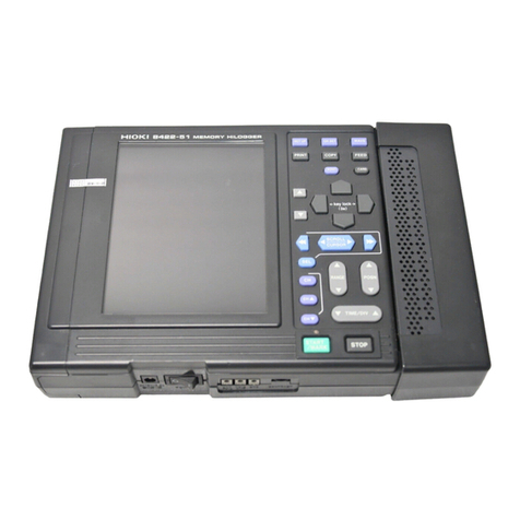
Hioki 3911-20 User manual

INSTRUCTION MANUAL
For...は専用機種。複数の場合は「/」で区切る。
不要の場合はとる。
形名を入力。 複数の場合は「/」で区切る。
3911-20
品名を入力。
COMMUNICATION BASE


Contents
Introduction i
Inspection i
Safety Notes ii
Notes on Use iii
Chapter 1 Overview 1
1.1 Product Overview 1
1.2 Name and Functions of Parts 2
Chapter 2 Application 3
2.1 Replacing the Battery 3
2.2 Installing Application Software 5
2.3 Connecting and Setting PC to the 3911-20 6
2.4 Connecting the 3911-20 with Logger 7
Chapter 3 Transferring Data 9
3.1 Measuring with Logger 9
3.2 Setting the 3911-20 10
3.3 Sending Setting Data 11
3.4 Receiving Measurement Data 12
3.5 Sending Measurement Data 13
3.6 Confirming and Clearing Loaded Data 14
Chapter 4 Specifications 15
Chapter 5 Maintenance and Service 17


i
_____________________________________________________________________
Inspection
______________________________________________________________
The latest version of COMMUNICATION UTILITY is
now available at our web site for downloading. Visit
our site at: http://www.hioki.co.jp/
Introduction
Ins
p
ection
Thank you for purchasing the HIOKI "3911-20
COMMUNICATION BASE." To obtain maximum
performance from the product, please read this manual first,
and keep it handy for future reference.
When you receive the product, inspect it carefully to ensure
that no damage occurred during If damage is evident, or if
it fails to operate according to the specifications, contact
your dealer or Hioki representative.
Accessories
Instruction Manual
LR03 alkaline battery X4
COMMUNICATION UTILITY Operation Guide
CD-R (COMMUNICATION UTILITY)
Note on shipping
Use the original packing materials when reshipping the
product, if possible.
Registered trademarks
Windows is a registered trademark of Microsoft
Corporation.
Pentium is a registered trademarks of Intel Corporation.

ii
_____________________________________________________________________
Safety Notes
______________________________________________________________
WARNING
This product is designed to conform to IEC 61010
Safety Standards, and has been thoroughly tested for
safety prior to shipment. However, mishandling during
use could result in injury or death, as well as damage
to the product. Be certain that you understand the
instructions and precautions in the manual before use.
We disclaim any responsibility for accidents or injuries
not resulting directly from product defects.
Safety Symbols
The symbol printed on the product indicates that the
user should refer to a corresponding topic in the
manual (marked with the symbol) before using the
relevant function.
In the manual, the symbol indicates particularly
important information that the user should read before
using the product.
Indicates DC (Direct Current).
WARNING
Indicates that incorrect operation presents a
significant hazard that could result in serious injury or
death to the user.
CAUTION Indicates that incorrect operation presents a
possibility of injury to the user or damage to the
product.
Safet
y
Notes
This manual contains information and warnings essential
for safe operation of the product and for maintaining it in
safe operating condition. Before using the product, be sure
to carefully read the following safety notes.
The following symbols in this manual indicate the relative
importance of cautions and warnings.

iii
_____________________________________________________________________
Notes on Use
______________________________________________________________
CAUTION The unit should always be operated in a range from -20
to 70 and 80% RH or less. During data transfer when
connected to personal computer (using RS-232C),
operating temperature range is from 0 to 40 .
If used outside the specified environmental ranges for
operation (or storage), the operation of the unit cannot be
guaranteed.
This product is not designed to be entirely water- or dust-
proof. To avoid damage, do not use it in a wet or dusty
environment.
Take care to avoid condensation. In particular, if there is a
sudden change of temperature (for example moving from a
cold place to a warm one), condensation is likely to occur.
Do not use the product where it may be exposed to
corrosive or combustible gases. The product may be
damaged or cause an explosion.
To avoid corrosion from battery leakage, remove the
batteries from the product if it is to be stored for a long
time.
Leaving the unit connected to an activated personal
computer hastens battery discharge.
When not using the unit, disconnect it from personal
computer.
Notes on Use
Follow these precautions to ensure safe operation and to
obtain the full benefits of the various functions.

iv
_____________________________________________________________________
Notes on Use
______________________________________________________________
Care and handling of CD-R
To keep disc clean from finger prints and prevent label
fading, carefully hold disc on the outer edge when
handling.
To prevent damage to label, do not expose disc to
alcohol based solvents or water.
When writing on label, use an oil base felt pen. Do not
write with a ball point pen or other hard tipped pens to
prevent scratching disc.
To prevent disc warping, do not expose disc to direct
sunlight, high temperature and high humidity.
Note on Used for COMMUNICATION UTILITY
Before using the software, please read these notes carefully.
HIOKI E.E. Corporation is the author of
COMMUNICATION UTILITY.
Except for the purposes of processing data from the
3911-20 or controlling the 3911-20, copying,
reproduction, or amendment in whole or in part of
COMMUNICATION UTILITY is prohibited by law.
For the purposes of product development,
COMMUNICATION UTILITY is subject to upgrading
without notice.
To publish material referencing COMMUNICATION
UTILITY, the prior consent of HIOKI is required. The
trademark "HIOKI" may not be used.
HIOKI cannot accept any responsibility whatever for the
results of a customer's operation of COMMUNICATION
UTILITY.

1
_____________________________________________________________________
Overview
______________________________________________________________
Chapter 1
Overview
1.1 Product Overview
The 3911-20 COMMUNICATION BASE loads data from
logger series and sends loaded data to personal computer.
Packaged application software allows personal computer to
load data from the 3911-20 and analyze loaded data.
Features
(1) Capable of collecting up to 16 channels of data when
connected to logger.
(2) Capable of storing setting conditions (clock, interval,
recording start time, etc.) in memory and loading
settings to logger when connected to logger.
(3) LED power indicator indicates battery replacement.
(4) Packaged software allows personal computer to load up
to 16 channels of data from logger series. Loaded data
can be applied to display graphs and calculate
maximum value, minimum value, etc.

2
_____________________________________________________________________
Overview
______________________________________________________________
②
①
③
1. SEND button Sends the 3911-20 settings to logger
series.
2. RECEIVE
button
Loads recorded data in logger to the
3911-20.
3. Optical data
transfer port
Enables optical data transfer to logger
series.
POWER Turns on when button is pressed or
connected to personal computer. Starts
blinking to indicate weak batteries.
TRANSMITTING Blinks during data transfer.
ERROR Starts blinking to indicate data transfer
error. Press either SEND button or
RECEIVE button to correct error.
FULL Blinks to indicate when all 16 channels
(8 channels maximum for the 3636-20/
3637-20/3638-20/3639-20/3640-20/
3645-20) of data have been loaded to
the 3911-20.
1.2 Name and Functions of Parts
LED condition

3
_____________________________________________________________________
Application
______________________________________________________________
WARNING
To avoid electric shock when replacing the batteries,
first disconnect the cable from the object to be
measured.
Do not mix old and new batteries, or different types of
batteries. Also, be careful to observe battery polarity
during installation. Otherwise, poor performance or
damage from battery leakage could result.
Handle and dispose of batteries in accordance with
local regulations.
Chapter 2
Application
2.1 Replacing the Battery
Battery Indicator
Under normal conditions LED power indicator is on. When
batteries are weak, LED power indicator starts blinking.
LED power indicator turns off after approximately 15
seconds with no operation.
When LED is blinking, data transfer is enabled with
personal computer but not available to logger.

4
_____________________________________________________________________
Application
______________________________________________________________
Note on Battery Replacement
Replace batteries when LED Power indicator is OFF.
Be sure to send data to be saved to personal computer
before replacing batteries although the 3911-20 data and
clock settings are saved for approximately one minute after
batteries are removed.
Do not remove batteries when LED power is on or blinking
to avoid losing the 3911-20 data and clock settings. LED
power indicator is turned off after approximately 15
seconds with no operation.
(1) Remove cover. Verify polarity and install four new
LR03 alkaline batteries
(2) Close cover.

5
_____________________________________________________________________
Application
______________________________________________________________
See COMMUNICATION UTILITY operation
guide to install and use application
software.
2.2 Installing Application Software
Packaged application software must be installed in personal
computer to use the 3911-20 and logger series.
Operating environment
Computer with Pentium 90 MHz CPU or higher
Microsoft Windows98/Me/2000/XP/Vista (32 bit version)
At least 32 MB of main memory
A display with 800 X600 dot resolution
At least 256 colors
At least 4 MB of empty space on the hard disk
COM port is necessary
Recommended environment
Computer with Pentium 200 MHz CPU or higher
Microsoft Windows2000/XP/Vista (32 bit version)
32 MB of main memory
A display with 800 X600 dot resolution
At least 65536 colors
At least 4 MB of empty space on the hard disk
COM port is necessary

6
_____________________________________________________________________
Application
______________________________________________________________
The same communication port settings
remain valid until communication is
reestablished.
Serial port is designated for
communications. Locate the mark
port in the back of personal computer.
D-sub
9
p
in female
D-sub
9
p
in female
Optional connection cables
compatible with the 3911-20
(PC/AT)
Connection: reversed
1DCD
2RxD
3TxD
4DTR
6DSR
7RTS
8CTS
5 GND
SHELL
1DCD
2RxD
3TxD
4DTR
6DSR
7RTS
8CTS
5 GND
SHELL
2.3 Connecting and Setting PC to the
3911-20
(1) Use RS-232C Cross Cable (the 3911-20 side: D-SUB9
pin) to connect personal computer to the 3911-20.
(2) Start up COMMUNICATION UTILITY from the
Windows start menu.
(3) Go to Communications on the menu bar and choose
Select Communication Port to specify the same port
(COM1 to COM6) as serial port on personal computer
connected to the 3911-20.
(4) Go to Communications and select Set Time to send
time of personal computer to the 3911-20. Make sure to
set correct time in personal computer before sending.
After installing and/or replacing batteries, make sure to
connect personal computer to the 3911-20 and set
current time in the 3911-20 with COMMUNICATION
UTILITY before using the 3911-20.
Corresponded cable
The 9637 RS-232C CABLE (1.8 m)

7
_____________________________________________________________________
Application
______________________________________________________________
Logger prong
When error occurs in the 3911-20, Press SEND
button or RECEIVE button on the 3911-20 to
reset. Logger returns to normal status. Open
interval setting display again (INTVL displayed)
and restart communication.
2.4 Connecting the 3911-20 with Logger
Align and insert logger prongs to the 3911-20 slots and
fasten logger securely to the 3911-20.
Improper connection between logger and the 3911-20
results communications failure and the 3911-20 error
indicator LED appears.

8
_____________________________________________________________________
Application
______________________________________________________________

9
_____________________________________________________________________
Transferring Data
______________________________________________________________
Prepare to measure. Load batteries in logger and the 3911-20.
Connect sensor and connection cable, etc.
Install application software included with the 3911-20.
Set the 3911-20 measurement conditions.
Use personal computer with application software COMMUNICATION UTILITY to set
measurement conditions. After completing, measurement conditions are sent to the
3911-20.
Send setting conditions from the 3911-20 to logger.
Connect the 3911-20 with logger and send setting conditions.
Measure data.
To start measurement with logger, options are manual start and prescheduled start.
To end measurement, options are manual stop and one time stop.
Retrieve measurement data from logger with the 3911-20.
Connect the 3911-20 and logger to retrieve measurement data.
Retrieve measurement data from the 3911-20 with personal computer.
Connect personal computer and the 3911-20 to retrieve measurement data.
Analyze and save measurement data with COMMUNICATION UTILITY.
See individual lo
gg
er instruction manuals.
See individual logger instruction
manual.
Chapter 3
Transferring Data
3.1 Measuring with Logger
Steps for basic measurement with logger

10
_____________________________________________________________________
Transferring Data
______________________________________________________________
Time
Interval
Recording method
Start control
Common settin
g
s
Each logger requires specific settings and
measurement conditions.
See Measurement condition settings in
COMMUNICATION UTILITY operation guide.
3.2 Setting the 3911-20
(1) Connect personal computer to the 3911-20.
(See Section 2.3,"Connecting and Setting PC to the
3911-20")
(2) Start up COMMUNICATION UTILITY on personal
computer.
(3) Go to 'Communications' on the menu bar and choose
'Set Measurement Conditions'.
(4) When measurement condition setting window is open,
go to '3911 setting item' and configure common logger
series settings such as interval and recording
preferences.
(5) After setting, select 'Send' to send settings to the 3911-
20.

11
_____________________________________________________________________
Transferring Data
______________________________________________________________
Time
Interval
Recording method
Start control
Common settin
g
s
Previously recorded logger data is erased
when recording is resumed. Be sure to load
data to be saved to the 3911-20 or to
personal computer before recording.
Communication with the 3911-20 is available
even when interval setting display is not
displayed except during recording or waiting
for recording start time. However, data
transfer is not possible when logger is set
sleep.
3.3 Sending Setting Data
(1) Press logger INTERVAL button lightly to display LCD.
(2) When REC mark or clock mark is displayed on logger
LCD, press REC/STOP button for more than one
second to stop recording. During recording or waiting
for recording start time, error occurs.
(3) Press logger INTERVAL button to open interval setting
display (INTVL displayed).
(4) Connect the 3911-20 to logger
series.
(5) Press the SEND button on the 3911-20 momentarily so
that the LED lights, then press and hold the same
button for one second to transfer logger series common
settings to the logger.

12
_____________________________________________________________________
Transferring Data
______________________________________________________________
Collected data
(with serial number )
Comments (when set)
Model 3631-20, 3641-20 8000 data X 16 ch (8 units)
Model 3632-20 to 3635-20 16000 data X 16 ch (16 units)
Model 3636-20, 3638-20 (1 ch) 32000 data X 8 ch (8 units)
Model 3636-20, 3638-20 (2 ch) 16000 data X 16 ch (8 units)
Model 3637-20, 3639-20
Model 3640-20, 3645-20 32000 data X 8 ch (8 units)
3.4 Receiving Measurement Data
(1) Press logger INTERVAL button lightly to display LCD.
(2) When REC mark or clock mark is displayed on logger
LCD, press REC/STOP button for more than one
second to stop recording. During recording or waiting
for recording start time, error occurs.
(3) Press logger INTERVAL button to open interval setting
display (INTVL displayed).
(4) Connect the 3911-20 to logger
series.
(5) Press the RECEIVE button on the
3911-20 momentarily so that the
LED lights, then press and hold the
same button for one second to
transfer measurement data from the logger to the 3911-
20.
Logger type determines number of channels applicable
in the 3911-20.
Table of contents
Other Hioki Conference System manuals
Popular Conference System manuals by other brands

Yealink
Yealink MeetingBar A20 quick start guide

Advanced Wireless Communications
Advanced Wireless Communications AWR-CB2200 Operator's manual

FONESTAR
FONESTAR SCI-700 instruction manual

Avaya
Avaya Scopia XT4300 Quick setup guide

Bosch
Bosch DCN multimedia user manual

Prentke Romich Company
Prentke Romich Company Accen Empower Unity Quick reference guide