manuals.online logo
Brands
  1. Home
  2. •
  3. Brands
  4. •
  5. Hioki
  6. •
  7. Measuring Instrument
  8. •
  9. Hioki 9666 User manual

Hioki 9666 User manual

100:1プローブ
100:1 PROBE
取扱説明書 / Instruction Manual
Dec. 2018 Revised edition 11
9666A980-11 18-12H
9666
JA/EN
はじめに
このたびは、HIOKI 9666 100:1プローブをご選定いただき、誠に
ありがとうございます。この製品を十分にご活用いただき、末長く
ご使用いただくためにも、取扱説明書はていねいに扱い、いつもお
手元に置いてご使用ください。
安全について
危険
この機器はIEC 61010 安全規格に従って、設計され、
試験し、安全な状態で出荷されています。測定方法を
間違えると人身事故や機器の故障につながる可能性が
あります。取扱説明書を熟読し、十分に内容を理解し
てから操作してください。万一事故があっても、弊社
製品が原因である場合以外は責任を負いかねます。
■機器上の記号
注意や危険を示します。機器上にこの記号が表示され
ている場合は、取扱説明書の該当箇所を参照ください。
二重絶縁または強化絶縁で保護されている機器を示し
ます。
■この取扱説明書で使用している記号
本書では、リスクの重大性および危険性のレベルを以下のように区
分して表記します。
危険作業者が死亡または重傷に至る切迫した危険があ
る場合について記述しています。
警告作業者が死亡または重傷を負うおそれがある場合
について記述しています。
必ず行っていただく「強制」事項を示します。
測定カテゴリについて
測定器を安全に使用するため、IEC61010では測定カテゴリとして、
使用する場所により安全レベルの基準をCAT Ⅱ〜 CAT Ⅳで分類し
ています。
危険
• カテゴリの数値の小さいクラスの測定器で、数値の
大きいクラスに該当する場所を測定すると重大な事
故につながるおそれがありますので、絶対に避けて
ください。
• カテゴリ表記のない測定器で、CAT Ⅱ〜 CAT Ⅳの測
定カテゴリを測定すると重大な事故につながるおそ
れがありますので、絶対に避けてください。
本器は CAT Ⅱに適合しています。
CAT Ⅱ: コンセントに接続する電源コード付き機器(可搬形工具・
家庭用電気製品など)の一次側電路コンセント差込口を
直接測定する場合。
CAT Ⅲ:
直接分電盤から電気を取り込む機器(固定設備)の一次側
および分電盤からコンセントまでの電路を測定する場合。
CAT Ⅳ:
建造物への引込み電路、引込み口から電力量メーターおよ
び一次側電流保護装置(分電盤)までの電路を測定する場合。
T
引込み口
引込み線
CAT ⅣCAT Ⅲ
CAT Ⅱ
分電盤 屋内配線
コンセント
固定設備
電力量メータ
ご使用にあたっての注意
本器を安全にご使用いただくために、また機能を十二分にご
活用いただくために、次の注意事項をお守りください。
危険
• 最大入力電圧
感電事故を防ぐため、プローブの入力部に最大入力
電圧を超える電圧を加えないでください。
• 最大対地間電圧
感電事故を防ぐため、プローブのGND と対地間は、測
定器の入力ユニットの対地間電圧以下にしてください。
8966, 8968, 8970, 8972, U8975, U8978 は300 Vで
す。
• 感電事故を防ぐため、ケーブル内部から白または赤色
部分(絶縁層)が露出していないか確認してください。
ケーブル内部の色が露出している場合は、使用しな
いでください。
警告
• 測定器本体の接地
感電事故を防ぐため、必ず測定器本体の保護接地を
してください。
• 測定対象物との接続
測定対象物にプローブを接続する時は、感電に注意
してください。また、感電事故を防ぐため、測定対
象物に接続したまま、測定器本体からプローブを外
さないでください。
測定器本体の接地について
• コンセントが接地形 2 極の場合
測定器本体に付属の接地形2 極電源コードを使用してくだ
さい。自動で接地状態になります。
• コンセントが接地形 2 極でない場合
測
定器本体に付属の接地アダプタを使用してください。この
場合、アダプタから出ている緑色の線を、必ず接地線に接続
してから測定器本体に付属の電源コードを接続してください。
仕様
分圧抵抗 99 MΩ1% at DC 100 V
99 MΩ+1%, -5 % at DC 1000 V
減衰比 100:1 3% at DC 100 V
100:1 +3%,-7% at DC 1000 V
(入力抵抗 1 MΩ1%の機器に対して)
最大入力電圧 5000 V peak(1 MHz以下)
3540 V rms (700 kHz 以下 )
最大対地間電圧 1000 V CATⅡ
8966、8968、8970、8972、U8975、U8978
使用時は 300 V CATⅡ
周波数特性 DC 〜200 MHz (プローブ単体 )
入力容量 7 pF以下 (プローブ単体 )
補償調整範囲 15 pF 〜45 pF
全長 約1.5 m
使用温湿度範囲 0℃〜 40℃、湿度 80% rh以下(結露しないこと)
保存温湿度範囲
-10℃〜 50℃、湿度 90% rh以下(結露しないこと)
使用場所 高度 2000 mまで、屋内
適合規格 EN 61010
汚染度2、測定カテゴリⅡ
(予想される過渡過電圧 6000 V)
製品保証期間 1年間
補償調整可能ユニット
8966 アナログユニット、8968 高分解能ユニット、8970
周波数ユニット、8972 DC/RMSユニット、U8975 4chア
ナログユニット、U8976 高速アナログユニット、U8978
4chアナログユニット
構成
フッククリップ
グランドリード
使用前点検
フッククリップとピンとの接触部にゴミなどが付着した場
合、測定に影響がでることがあります。使用前に接触部をや
わらかい布で拭くなどのクリーニングを行ってください。ま
た、定期的なクリーニングも行ってください。
使用方法
各機種の外部制御用端子、または発振器から 1 kHz の方形波
を出力させます。プローブ手持ち部のボリュームを調節して
波形を調整します。
※詳細は各機種の取扱説明書をご覧ください。
調整された波形
調整不足の波形
1 2 3 4
100:1 PROBE
Instruction Manual
Dec. 2018 Revised edition 11
9666A980-11 18-12H
9666
barcode(35×7 mm)
EN
Warranty
Warranty malfunctions occurring under conditions of normal use in
conformity with the Instruction Manual and Product Precautionary
Markings will be repaired free of charge. This warranty is valid
for a period of one (1) year from the date of purchase. Please
contact the distributor from which you purchased the product for
further information on warranty provisions.
Introduction
Thank you for purchasing the HIOKI Model 9666 100:1 PROBE.
To obtain maximum performance from the product, please read
this manual rst, and keep it handy for future reference.
Safety Notes
DANGER
This product is designed to conform to IEC 61010
Safety Standards and has been thoroughly tested
for safety prior to shipment. However, using the
product in a way not described in this manual may
negate the provided safety features.
Before using the product, be certain to carefully
read the following safety notes:
Symbols afxed to the Instrument
Indicates cautions and hazards. When the symbol is
printed on the product refer to a corresponding topic in
the Instruction Manual.
Indicates a product that has been protected throughout
by double insulation or reinforced insulation.
Notations
In this manual, the risk seriousness and the hazard levels are
classied as follows.
DANGER
Indicates an imminently hazardous situation that
will result in death or serious injury to the operator.
WARNING
Indicates that incorrect operation presents a
signicant hazard that could result in serious
injury or death to the user.
Indicates the compulsory action.
Measurement categories
To ensure safe operation of measuring instruments, IEC 61010
establishes safety standards for various electrical environments,
categorized as CAT II to CAT IV, and called measurement categories.
DANGER
•Using a measuring product in an environment
designated with a higher-numbered category than
that for which the product is rated could result in
a severe accident, and must be carefully avoided.
•Never use a measuring product that lacks category
labeling in a CAT II to CAT IV measurement environment.
Doing so could result in a serious accident.
This product complies with CAT II safety requirements.
CAT II: When directly measuring the electrical outlet receptacles
of the primary electrical circuits in equipment connected to an
AC electrical outlet with a power cord (portable tools, household
appliances, etc.)
CAT III: When measuring the primary electrical circuits of heavy
equipment (fixed installations) connected directly to the distribution
panel, and feeders from the distribution panel to outlets
CAT IV: When measuring the circuit from the service drop to the
service entrance, and to the power meter and primary overcurrent
protection device (distribution panel)
T
Distribution panel
Service drop
CAT IV CATⅢ
CAT II
Internal wiring
Outlet
Fixed installation
Power meter
Service entrance
Notes on Use
Follow these precautions to ensure safe operation and to obtain the
full benets of the various functions.
DANGER
•Maximum input voltage
To prevent electrical shock, do not apply voltages
to the probe
input that exceeds the maximum input voltage.
•Maximum voltage to ground
To prevent electrical shock, make sure that the
voltage to ground from probe GND does not
exceed the voltage to ground from the input unit
of the measurement instrument.
8966, 8968, 8970, 8972, U8975, U8978: 300 V
•To prevent an electric shock accident, conrm
that the white or red portion (insulation layer)
inside the cable is not exposed. If a color inside
the cable is exposed, do not use the cable.
WARNING
•Grounding the measurement instrument To avoid
electrical shock, always ground the measurement
instrument.
•Connecting to the circuit to be measured
When connecting the probe to a circuit for
measurement, take care to avoid electrical shock.
Furthermore, to avoid electrical shock do not
disconnect the probe from the measurement
instrument while it is still connected to the circuit
being measured.
Grounding the measurement
instrument
When the AC outlet of the measurement instrument is of the
grounded three-pin type: Use the grounded three-core power
cord supplied. The product will be grounded automatically.
Specifications
Divider resistance 99 MΩ±1 % at DC 100 V
99 MΩ+1 %, - 5 % at DC 1000 V
Attenuation ratio 100:1 ±3 % at DC 100 V
100:1 +3 %, -7 % at DC 1000 V
(In conjunction with measuring instrument
with an input impedance of 1M ohm ±1%)
Maximum input
voltage
5000 V peak (max. 1 MHz)
3540 V rms (Max. 700 kHz)
Maximum rated
voltage to earth
1000 V CAT II
8966, 8968, 8970, 8972, U8975, U8978:
300 V CAT II
Frequency
characteristic
DC to 200 MHz (probe only)
Input capacitance Max. 7 pF (probe only)
Compensation
adjustment range
15 pF to 45 pF
Total length Approx. 1.5 m
Operating
temperature and
humidity range
0°C to 40°C
Relative humidity: 80% RH or less
(with no condensation)
Storage
temperature and
humidity range
-10°C to 50°C
Relative humidity: 90% RH or less
(with no condensation)
Location for use Altitude up to 2000 m (6562 feet), indoors
Standard Applying EN 61010
Pollution degree 2, Measurement category II
(Anticipated Transient Overvoltage: 6000 V)
Product warranty
period
1 year
Applicable Modules
8966 Analog Unit, 8968 High Resolution Unit, 8970 Freq Unit,
8972 DC/RMS Unit, U8975 4ch Analog Unit,
U8976 High Speed Analog Unit, U8978 4ch Analog Unit
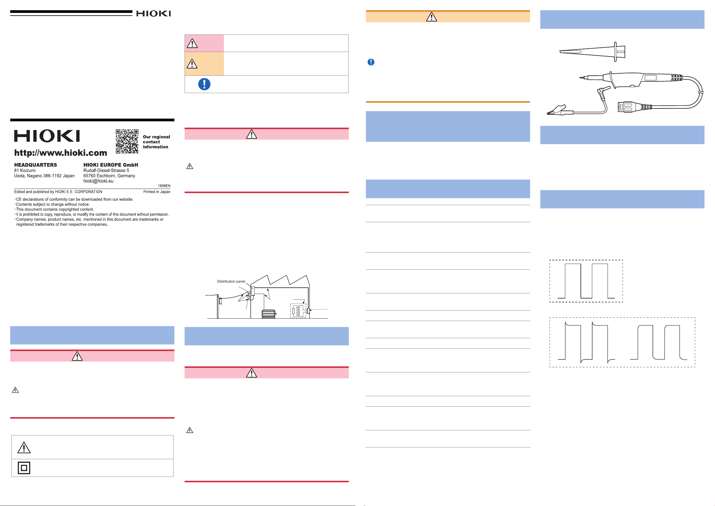
Contents of the Package
Hook clip
Ground lead
Inspection before use
Measurements may be degraded by dirt on the contacting
parts of the hook clip and pin. Clean the contacting parts by
gently wiping with a soft cloth before use. Remember to clean
them regularly as well.
Using the Probe
Use a terminal for external control or a waveform generator to
output a square wave of 1 kHz.
Adjust the waveform by turning the dial of the probe grip.
* Refer to the instruction manual of the each instrument for
details.
Adjusted waveform
Insufciently-adjusted waveform
1 3 4

Other Hioki Measuring Instrument manuals

Hioki 8870-20 User manual

Hioki

Hioki 8870-20 User manual

Hioki PW3198 User manual

Hioki

Hioki PW3198 User manual

Hioki 3273 User manual

Hioki

Hioki 3273 User manual

Hioki PW8001-01 User manual

Hioki

Hioki PW8001-01 User manual

Hioki 3332 User manual

Hioki

Hioki 3332 User manual

Hioki CT6845A User manual

Hioki

Hioki CT6845A User manual

Hioki CM4375 User manual

Hioki

Hioki CM4375 User manual

Hioki 3126-01 User manual

Hioki

Hioki 3126-01 User manual

Hioki TM6102 User manual

Hioki

Hioki TM6102 User manual

Hioki MR8847A User manual

Hioki

Hioki MR8847A User manual

Hioki CM4001 User manual

Hioki

Hioki CM4001 User manual

Hioki RM3545A-1 User guide

Hioki

Hioki RM3545A-1 User guide

Hioki CM4141 User manual

Hioki

Hioki CM4141 User manual

Hioki IM7585 Series Use and care manual

Hioki

Hioki IM7585 Series Use and care manual

Hioki RM3542-50 User manual

Hioki

Hioki RM3542-50 User manual

Hioki Super megohm SM7110 User manual

Hioki

Hioki Super megohm SM7110 User manual

Hioki CM4371 User manual

Hioki

Hioki CM4371 User manual

Hioki MR8847-51 User manual

Hioki

Hioki MR8847-51 User manual

Hioki 8847 User manual

Hioki

Hioki 8847 User manual

Hioki CM3286 User manual

Hioki

Hioki CM3286 User manual

Hioki CM3286 User manual

Hioki

Hioki CM3286 User manual

Hioki 9605 User manual

Hioki

Hioki 9605 User manual

Hioki PW3198 User manual

Hioki

Hioki PW3198 User manual

Hioki SM9001 User manual

Hioki

Hioki SM9001 User manual

Popular Measuring Instrument manuals by other brands

Magnetrol Pulsar R96 Functional safety manual

Magnetrol

Magnetrol Pulsar R96 Functional safety manual

Ralston Instruments LC-20 quick start guide

Ralston Instruments

Ralston Instruments LC-20 quick start guide

dacell DN-10W user manual

dacell

dacell DN-10W user manual

Variable Spectro 1 Getting started

Variable

Variable Spectro 1 Getting started

Oceanic Systems 5700 user manual

Oceanic Systems

Oceanic Systems 5700 user manual

Endress+Hauser Solitrend MMP40 operating instructions

Endress+Hauser

Endress+Hauser Solitrend MMP40 operating instructions

Flow vision FC50-EX manual

Flow vision

Flow vision FC50-EX manual

Sartorius Docu-pH Operation manual

Sartorius

Sartorius Docu-pH Operation manual

TUF HD 80 G operating manual

TUF

TUF HD 80 G operating manual

Molecular Devices SPECTRAmax PLUS 384 Operator's manual

Molecular Devices

Molecular Devices SPECTRAmax PLUS 384 Operator's manual

Quantum Composers miniSystem Series operating manual

Quantum Composers

Quantum Composers miniSystem Series operating manual

PCB Piezotronics ICP HTM354C03 Installation and operating manual

PCB Piezotronics

PCB Piezotronics ICP HTM354C03 Installation and operating manual

Precision Digital Corporation Helios PD2-6300 instruction manual

Precision Digital Corporation

Precision Digital Corporation Helios PD2-6300 instruction manual

Badger Meter Primo Advanced BMAG-350-icpf Instruction and operation manual

Badger Meter

Badger Meter Primo Advanced BMAG-350-icpf Instruction and operation manual

Schmidt MST Series instruction manual

Schmidt

Schmidt MST Series instruction manual

ISKRAEMECO MT174 manual

ISKRAEMECO

ISKRAEMECO MT174 manual

AccuEnergy AcuRev 1310 Series user manual

AccuEnergy

AccuEnergy AcuRev 1310 Series user manual

Gill Instruments WindObserver II user manual

Gill Instruments

Gill Instruments WindObserver II user manual

manuals.online logo
manuals.online logoBrands
  • About & Mission
  • Contact us
  • Privacy Policy
  • Terms and Conditions

Copyright 2025 Manuals.Online. All Rights Reserved.