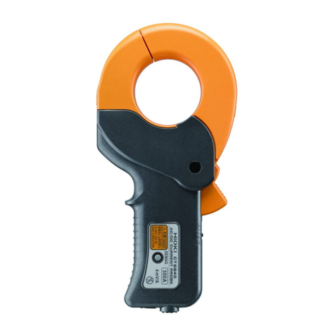
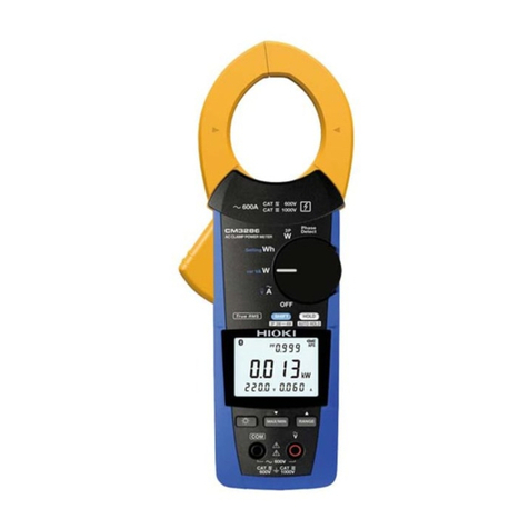
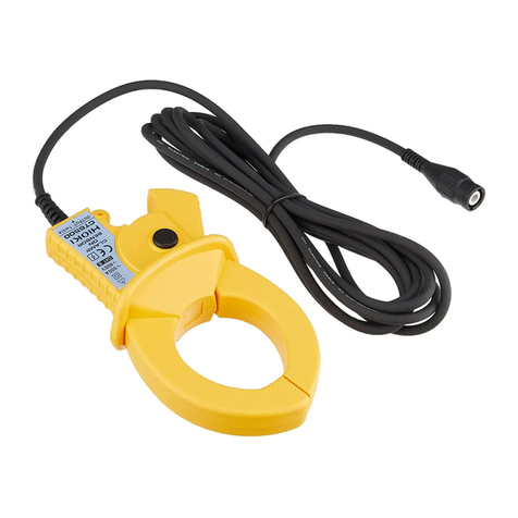
Hioki 3290 User manual

INSTRUCTION MANUAL
CLAMP ON
3290
AC/DC HiTESTER


i
Contents
Introduction ............................................................. 1
Inspection ............................................................... 2
Safety Notes ........................................................... 3
Usage Notes........................................................... 6
Organization of This Manual ................................. 10
Chapter 1 Overview 13
1.1 Product Overview ................................. 13
1.2 Features ................................................ 13
1.3 Parts Names and Functions ................. 16
1.3.1 3290
CLAMP ON AC/DC HiTESTER ........16
1.3.2 9691, 9692, 9693
CLAMP ON AC/DC SENSOR .......... 24
1.4 Flowchart Of Key Operations ................ 25
1.4.1 Current Measurements Mode ..........25
1.4.2 Frequency Mode .............................. 28
1.5 Modes ...................................................29
Chapter 2
Basic Measurement Procedures 35
2.1 DC Measurement (DC A) ...................... 36
2.2 AC Measurement (AC A) ......................38
2.3 Peak Measurement In AC+DC A Mode 39

ii
Chapter 3 Measurement Procedures 43
3.1 Preparations ..........................................43
3.2 Current Measurement ...........................45
3.2.1 Measuring DC Current (DC A) ..........46
3.2.2 Measuring AC Current (AC A) ..........47
3.2.3 Measuring AC + DC Current (AC+DC A)
...........................................................49
3.2.4 Bar Graph .........................................50
3.2.5 Peak Measurement ...........................51
3.2.6 Output Function
(Current Measurement) .....................53
3.3 Frequency Measurement ......................57
3.3.1 Frequency Measurement ..................57
3.3.2 Output Function
(Frequency Measurement) ................58
3.4 Auto-Zero Adjustment Function .............60
3.5 Data Hold Function ................................61
3.6 Changing the Screen Update Rate .......61
3.6.1 SLOW Mode .....................................61
3.6.2 FAST Mode .......................................62
3.7 Recording Function ...............................63
3.7.1 Measurement Reading ......................63
3.7.2 Display of Elapsed Time ...................64
3.7.3 Interrupting the Recording Function ..64
3.7.4 Clearing Recorded Data ...................64
3.7.5 Disabling the Recording Function .....65
3.8 Measurement Method
Switching Function ................................66
3.8.1 RMS Measurement ...........................66
3.8.2 MEAN Measurement .........................66
3.9 Measurement Response Speed
Switching Function ................................67

iii
3.9.1 NORMAL Mode ................................ 67
3.9.2 SLOW Mode ..................................... 67
3.9.3 FAST Mode ...................................... 67
3.10 Filter Function ....................................... 70
3.11 Key Lock Function ................................71
3.12 Bar Graph Enlargement Function .........71
3.13 Battery Check Function ........................72
3.14 MON Output Filter Function ..................73
3.15 Auto Power Off Function .......................74
3.16 Setting the Save Function ..................... 75
3.17 Battery-Low Warning ............................ 76
3.18 Beep Tone ............................................ 77
Chapter 4 Batteries Replacement 79
Chapter 5 AC Adapter 81
Chapter 6 Attaching the Strap 83
Chapter 7 Specifications 85
7.1 Measurement Specifications ................. 85
7.2 General Specifications .......................... 88
Chapter 8 Clamp Sensor Specifications 93
8.1 9691 CLAMP ON AC/DC SENSOR ...... 93
8.2 9692 CLAMP ON AC/DC SENSOR ...... 96
8.3 9693 CLAMP ON AC/DC SENSOR ...... 99

iv
Chapter 9 Carrying Case 103
Chapter 10 Troubleshooting 105
Chapter 11 After-sale Service 111
11.1 Cleaning ..............................................111
11.2 Service ................................................111
Chapter 12 Appendix 113
12.1 Combined Accuracy ............................113
12.1.1Accuracy Tables .............................113
12.1.2Method of Calculation .....................118
12.2 Use of Intermediate Cable ...................119

1
Thank you for purchasing the HIOKI "3290 CLAMP ON
AC/DC HiTESTER". To obtain maximum performance
from the product, please read this manual first, and keep it
handy for future reference.
This manual describes the operation of the 3290 when
used with the 9691, 9692, or 9693 CLAMP ON AC/DC
SENSOR.
Request We have tried to bring this manual as close to perfection
as we could achieve. If perchance you find any unclear
portions, mistakes, omissions, or the like, we would be
most obliged if you could please notify us of them via any
HIOKI agent, or directly.
Introduction

2
• When you receive the product, inspect it carefully
to ensure that no damage occurred during ship-
ping. In particular, check the accessories, panel
switches, and connectors. If damage is evident, or
if it fails to operate according to the specifications,
contact your dealer or Hioki representative.
• Before using the product the first time, verify that it
operates normally to ensure that the no damage
occurred during storage or shipping. If you find any
damage, contact your dealer or Hioki representa-
tive.
Accessories
Strap .........................................................................................................1
LR6 Manganese battery............................................................................4
Instruction Manual.....................................................................................1
Options
9400 CARRYING CASE
9094 OUTPUT CORD
9445-02 AC ADAPTER (SA10-0910N, SINO-AMERICAN)
9445-03 AC ADAPTER (EU) (SA10-0910G, SINO-AMERICAN)
9691 CLAMP ON AC/DC SENSOR
9692 CLAMP ON AC/DC SENSOR
9693 CLAMP ON AC/DC SENSOR
Inspection

3
This manual contains information and warnings essential
for safe operation of the product and for maintaining it in
safe operating condition. Before using the product, be
sure to carefully read the following safety notes.
Safety Symbols
Safety Notes
This product is designed to conform to IEC
61010 Safety Standards, and has been thor-
oughly tested for safety prior to shipment.
However, mishandling during use could
result in injury ordeath, as well as damage to
the product. Be certain that you understand
the instructions and precautions in the man-
ual before use. We disclaim any responsibil-
ity for accidents or injuries not resulting
directly from product defects.
In the manual, the symbol indicates particu-
larly important information that the user should
read before using the product.
The symbol printed on the product indicates
that the user should refer to a corresponding topic
inthemanual(markedwiththe symbol) before
using the relevant function.
Indicates a double-insulated device.
Indicates DC (Direct Current).
Indicates AC (Alternating Current).
Indicates both DC (Direct Current) and AC (Alter-
nating Current).
Indicates that the instrument may be connected to
or disconnected from a live circuit.

4
The following symbols in this manual indicate the relative
importance of cautions and warnings.
Other Symbols
Accuracy We define measurement tolerances in terms of f.s. (full
scale), rdg. (reading) and dgt. (digit) values, with the
following meanings:
Indicates that incorrect operation presents an ex-
treme hazard that could result in serious injury or
death to the user.
Indicates that incorrect operation presents a sig-
nificant hazard that could resultin serious injury or
death to the user.
Indicates that incorrect operation presents a pos-
sibility of injury to the user or damage to the prod-
uct.
Advisory items related to performance or correct
operation of the product.
Indicates the prohibited action
f.s. (maximum display value or scale length)
The maximum displayable value or the full length
of the scale. This is usually the maximum value of
the currently selected range.
rdg. (reading or displayed value)
The valuecurrently beingmeasured andindicated
on the measuring product.
dgt. (resolution)
The smallest displayable unit on a digital measur-
ing product, i.e., the input value that causes the
digital display to show a "1".

5
Measurement categories (Overvoltage categories)
This product complies with CATIII (600 V), CATII (1000 V)
safety requirements.
To ensure safe operation of measurement products, IEC
61010 establishes safety standards for various electrical
environments, categorized as CAT I to CAT IV, and called
measurement categories. These are defined as follows.
Higher-numbered categories correspond to electrical
environments with greater momentary energy. So a
measurement device designed for CAT III environments
can endure greater momentary energy than a device
designed for CAT II.
Using a measurement product in an environment
designated with a higher-numbered category than that for
which the product is rated could result in a severe
accident, and must be carefully avoided.
Never use a CAT I measuring iproduct in CAT II, III, or IV
environments.
The measurement categories comply with the
Overvoltage Categories of the IEC60664 Standards
CAT I Secondary electrical circuits connected to an AC electri-
cal outlet through a transformer or similar device.
CAT II Primary electrical circuits in equipment connected to an
AC electrical outlet by a power cord (portable tools,
household appliances, etc.)
CAT III Primary electrical circuits of heavy equipment (fixed in-
stallations) connected directly to the distribution panel,
and feeders from the distribution panel to outlets.
CAT IV The circuit from the service drop to the service entrance,
and to the power meter and primary overcurrent
protection device (distribution panel).

6
Follow these precautions to ensure safe operation and to
obtain the full benefits of the various functions.
Usage Notes
• To avoid short circuits and potentially life-
threatening hazards, never attach the
product to a circuit that operates at more
than the 600V, or over bare conductors.
• Clamp sensor should only be connected to
the secondary side of a breaker, so the
breaker can prevent an accident if a short
circuit occurs. Connections should never
be made to the primary side of a breaker,
because unrestricted current flow could
cause a serious accident if a short circuit
occurs.
• Use only the specified Model 9445-02 AC
ADAPTER (SA10-0910N, SINO-AMERI-
CAN) or 9445-03 (for EU) AC ADAPTER
(SA10-0910G, SINO-AMERICAN).
AC adapter input voltage range is 100 to
240 VAC (with ±10% stability) at 50/60 Hz.
To avoid electrical hazards and damage to
the product, do not apply voltage outside of
this range.
• To avoid electric shock, do not allow the
product to get wet, and do not use it when
your hands are wet.
• Do not use the product where it may be
exposed to corrosive or combustible
gases. The product may be damaged or
cause an explosion.

7
• The top part of the clamp sensor above the
barrier (including the clamps, but not the
lever) is provided with double insulation to
ensure safety. Be careful not to drop the
sensor or otherwise subject it to impact. A
damaged sensor may result in electric
shock during measurement. In case of
sensor damage, contact us immediately for
repair or discard the damaged sensor to
avoid subsequent use.
• To avoid damage to the product, do not
exceed the maximum input current rating,
which depends on the frequency of the
current being measured (see Chapter 8
Clamp Sensor Specifications - Frequency-
dependent deletion characteristics) Be
careful about the evolution of heat, when
the input frequency is high.
• To avoid electric shock when replacing the
batteries, first disconnect the clamp from
the object to be measured.
• After replacing the batteries, replace the
cover and screws before using the
product.
• Do not mix old and new batteries, or
different types of batteries. Also, be careful
to observe battery polarity during
installation. Otherwise, poor performance
or damage from battery leakage could
result.
• To avoid the possibility of explosion, do not
short circuit, disassemble or incinerate
batteries.
• Handle and dispose of batteries in
accordance with local regulations.

8
• Do not use the product when the battery is
depleted ( lights on the LCD). When
is on, accuracy and other specifications cannot
be guaranteed.
• For the inside memory protection, make sure
the power is turned off before plugging in or
unplugging the AC adapter.
• Adjustments and repairs should be made only
by technically qualified personnel.
• If the protective functions of the product are
damaged, either remove it from service or mark
it clearly so that others do not use it inadvert-
ently.
• To avoid corrosion from battery leakage, remove
the batteries from the product if it is to be stored
for a long time.

9
Observe the following to avoid damage to the
product.
• Installation and Operating Environment
Between 0°C and 40°C; 80% RH or less;
indoors only.
• Do not store or use the product where it could
be exposed to direct sunlight, high temperature
or humidity, or condensation. Under such condi-
tions, the product may be damaged and insula-
tion may deteriorate so that it no longer meets
specifications.
• This product is not designed to be entirely
water- or dust-proof. To avoid damage, do not
use it in a wet or dusty environment.
• Do not use the product near a device that gener-
ates a strong electromagnetic field or electro-
static charge, as these may cause erroneous
measurements.
• To avoid damage to the product, protect it from
vibration or shock during transport and handling,
and be especially careful to avoid dropping.
Direct
sunlight
High temper
-
ature, high
humidity, du
st
Electromag
-
n
etic radiatio
n
Impact,
dropping
• Accurate measurement may be impossible in the
presence of strong magnetic fields, such as near
transformers and high-current conductors, or in
the presence of strong electromagnetic fields
such as near radio transmitters.
• To clean the product, wipe it gently with a soft
cloth moistened with water or mild detergent.
Never use solvents such as benzene, alcohol,
acetone, ether, ketones, thinners or gasoline, as
they can deform and discolor the case.

10
Chapter 1 Product Overview
Provides an overview of the product and describes the
parts and functions.
Chapter 2 Basic Measurement Procedure
Describes the basic measurement procedure for quick
reference and the peak measurement procedure in DC
current (DC A) mode, AC current (AC A) mode, and
AC+DC A mode.
Chapter 3 Measurement Procedure
Describes the measurement procedure for the 3290
CLAMP ON AC/DC HiTESTER when combined with the
9691, 9692, or 9693 CLAMP ON AC/DC SENSOR.
Chapter 4 Battery Replacement
Explains how to replace the battery used for the 3290
Clamp On AC/DC HiTESTER.
Chapter 5 AC Adapter
Explains how to use the 9445-02 AC Adapter (optional).
Chapter 6 Attaching the Strap
Explains how to attach the strap.
Chapter 7 Specifications
Lists the specifications of the 3290 CLAMP ON AC/DC
HiTESTER.
Chapter 8 Clamp Sensor Specifications
Lists the specifications of the 9691, 9692, and 9693
CLAMP ON AC/DC SENSORs.
Chapter 9 Carrying Case
Explains how to use the 9400 CARRYING CASE
(optional).
Organization of This Manual

11
Chapter 10 Troubleshooting
Lists common symptoms that may indicate a malfunction.
If you encounter a problem, be sure to read this chapter
before requesting repair.
Chapter 11 Service
Describes our customer support service.
Chapter 12 Appendix
• Provides the accuracy table and explains how to
calculate accuracy for the 3290 CLAMP ON AC/
DC HiTESTER when combined with the 9691,
9692, or 9693 CLAMP ON AC/DC SENSOR.
• Describes how to use the intermediate cable.

12

13
Chapter 1 Overview
The 3290 CLAMP ON AC/DC HiTESTER is used with the
9691, 9692, or 9693 CLAMP ON AC/DC SENSOR.
These sensors are interchangeable and any model can
be used with the 3290. The 3290 automatically detects
the sensor connected and sets up the appropriate range.
When combined with the 9691, 9692, or 9693 Sensor, the
3290 HiTESTER can perform DC, AC, and AC+DC
measurement of a live power line. Various functions are
available (using the SHIFT key) to make the 3290 suitable
for various current measurement applications. The 3290
is also equipped with two output terminals to enable a
variety of advanced measurements, such as simultaneous
output of both monitor and rms record. Moreover, the
3290 can operate using battery power or the AC adapter
(for long-term measurement use).
The 3290 has the following features:
Multifunction Microcomputer
The 3290 both compact and multifunctional thanks to the
built-in microcomputer and use of the SHIFT key.
Large-Screen LCD
The large-screen LCD employed is easy to read.
Clamp Sensor
The 3290 is compatible with three clamp-on AC/DC
sensors (9691, 9692, and 9693) having different ratings.
Because the 3290 automatically detects the sensor
connected, you need not edit the setting each time you
change the sensor.
Overview Chapter 1
1.1 Product Overview
1.2 Features

Chapter 1 Overview
14
Multifunction Microcomputer
The 3290 both compact and multifunctional thanks to the
built-in microcomputer and use of the SHIFT key.
Large-Screen LCD
The large-screen LCD employed is easy to read.
Clamp Sensor
The 3290 is compatible with three clamp-on AC/DC
sensors (9691, 9692, and 9693) having different ratings.
Because the 3290 automatically detects the sensor
connected, you need not edit the setting each time you
change the sensor.
Two Output Terminals
Two signals are output simultaneously from among the
four following: current (REC = record and MON =
monitor), current frequency (REC = record), and low
battery warning signal.
• Current monitor & low battery warning signal
• Current monitor & current record
• Current record & low battery warning signal
• DC component & AC component (AC/DC sepa-
rate output)
• Frequency record & current record
Method of measurement
In AC A mode, you can select either the true rms (RMS)
or average rectified rms indication (MEAN).
Measurement Response Speed
For RMS measurement, you can select a response speed
from FAST, NORMAL, or SLOW.
Low-frequency Current Measurement
In AC+DC A mode, you can measure current from 1 Hz
when the measurement response speed is set to SLOW.
Filter Function
This function turns on and off a low-pass filter (LPF) of
approximately 500 Hz.
Setting Save Function
This function saves the current measurement conditions
so that settings are retained even after power is turned
OFF.
Key Lock Function
This locks all keys including the POWER key (except the
keys used to unlock).
Table of contents
Other Hioki Measuring Instrument manuals

Hioki
Hioki FT3432 User manual

Hioki
Hioki 8847 User manual

Hioki
Hioki PQ3198 User manual

Hioki
Hioki RM3548 User manual

Hioki
Hioki HiTester 3443-01 User manual

Hioki
Hioki FT3424 User manual

Hioki
Hioki RM3545A-1 User guide

Hioki
Hioki 8835-01 User manual

Hioki
Hioki LR8400-92 User manual

Hioki
Hioki PQ3100-91 User manual