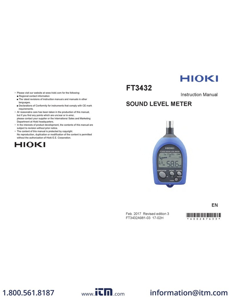
Hioki 9605 User manual

INSTRUCTION MANUAL
For...は専用機種。複数の場合は「/」で区切る。不要の場合はとる。
For 3193,3193-10
形名を入力。 複数の場合は「/」で区切る。
9605
品名を入力。
HARMONIC/FLICKER
MEASUREMENTS UNIT
July 2012 Revised edition 4 9605A981-04 12-07H


Contents
Introduction i
Chapter 1 Overview and Features 1
1.1 Product Overview 1
1.2 Features 2
Chapter 2 Key Operations and the Screen Configuration 3
2.1 Key Operations 3
2.2 Screen Configuration 3
Chapter 3 Setting the Basic Functions 5
3.1 Setting the Wiring Mode (1P2W to 3P4W) 5
3.2 Analysis Channel Selection 6
3.3 PLL Source Setting 7
3.4 Setting the Analysis Mode (Harmonic/Flicker) 8
3.5 Setting the Coupling Mode (Harmonic/Flicker) 8
3.6 Switching the Voltage Range and Current Range
(Harmonic/Flicker) 9
3.7 Setting the Low-pass Filter (Harmonic/Flicker) 9
3.8 Degaussing (Harmonic) 9
3.9 Zero Adjustment Operation (Harmonic/Flicker) 10
3.10 Averaging Setting (Harmonic) 10
3.11 Time Constant Setting (Harmonic) 11
3.12 Measurement by External Trigger (Harmonic) 12
3.13 Setting the Pst Time and Plt Times (Flicker) 13
3.14 Connection Conversion Function 14
3.15 Limit Multiplication Setting Function (Flicker) 15
Chapter 4 Harmonic Measurement 17
4.1 Harmonic Analysis Procedure 18
4.2 Harmonic Measurement 19
4.3 Graph Display of Harmonics 21
4.4 List Display of Harmonics 25
4.5 Vector Display of Harmonics 28
4.6 Waveform Display 30

Chapter 5 Flicker Measurement 35
5.1 Flicker Measurement Procedure 38
5.2 Measurement Value Display 39
5.3 CPF Display 41
5.4 Pst Display 43
5.5 Monitor Display 45
Chapter 6 Hold/Peak Hold Function 47
6.1 Hold Function 47
6.1.1 Harmonic Analysis 47
6.1.2 Flicker Measurement 47
6.2 Peak Hold Function 48
6.2.1 Harmonic Analysis 48
6.2.2 Flicker Measurement 48
Chapter 7 Output to Floppy Disk/Printer 49
7.1 Selecting the Output Item to FDD/Printer 50
7.1.1 Output Setting in Harmonic Analysis Mode 50
7.1.2 Output Setting in Flicker Measurement Mode 51
7.2 Timer Control of Output 52
7.2.1 Harmonic Analysis 52
7.2.2 Flicker Measurement 52
7.2.3 Relationship Between the Number of Output Items
and Interval Time 53
Chapter 8 External Control 57
8.1 EXT.CLOCK 57
8.2 TRIGGER.IN 58
8.3 TRIGGER.OUT 58

Chapter 9 GP-IB/RS-232C Interface 59
9.1 Overview 59
9.2 Event Registers 60
9.3 Command Reference 61
9.3.1 Command Reference Explanation 61
9.3.2 Commands for Switching Harmonic Analysis/
Flicker Measurement 62
9.3.3 Specific Commands for Harmonic Analysis Function 63
9.3.4 Specific Commands for Flicker Measurement 77
9.4 Specific Commands Reference 89
9.5 Valid Commands for Each Status 93
9.6 Specific Command Tree 96
9.7 The Output Item Bits 98
Chapter 10Specifications 101
10.1 Harmonic Analysis Function 101
10.2 Flicker Measurement Function 107
Appendix APPENDIX 1
Index INDEX 1


i
────────────────────────────────────────────────────
Introduction
────────────────────────────────────────────────────
NOTE
Introduction
Thank you for purchasing this HIOKI 9605 HARMONIC/FLICKER
MEASUREMENTS UNIT. To get the maximum performance from the unit,
please read this manual first, and keep this at hand.
・The HIOKI 3193, 3193-10 POWER HiTESTER will be referred to as the
HIOKI 3193in this manual.
・This unit is designed for installation in the HIOKI 3193, 3193-10 POWER
HiTESTER to enable harmonic analysis and flicker measurement. For details
on operation of the HIOKI 3193, please refer to its instruction manual.
・Harmonic analysis and flicker measurement cannot both be performed at the
same time.
・The 9605 measures flicker in terms of voltage fluctuations. The specific
measurement parameters are as follows:
Voltage measurements d measurements (dc, dmax, d(t)500ms)
Flicker measurements (Pst, Plt)
・This unit is a factory-fitted option. When the HIOKI 3193 unit is powered
on, you can check the installation on the screen.
・For operating environment, maintenance, and disposal at end of life, the
same conditions apply as to the main 3193 unit.
・Because of differences in measurement principle, frequency response, and
accuracy, the values measured by the 9605 (effective voltage value, effective
current value, active power, and phase difference) may not agree with values
measured by 9600/9601/9602 units installed in the same 3193 unit.
・The 9605 does not save analysis data if there is a power failure. All data
values from before the power failure are treated as zero. However, time
averaging values, peak hold values, and similar data values are preserved
when there is a power failure.
・The D/A output is not possible for the analyzed data by the 9605.
・For Flicker measurement, cumulative integration is not possible.
・The HIOKI 3193-10 does not come with a floppy disk drive (FDD). Even if
there is no special mention in the instruction manual, the FDD will not be
supported when using the 9605 unit in the 3193-10.
ii
────────────────────────────────────────────────────
Introduction
────────────────────────────────────────────────────
Safety Read the Instruction Manual supplied with the HIOKI 3193 unit very
carefully, and follow the indications given under "DANGER," "WARNING,"
"CAUTION," and "NOTE."
Beforeuse Before using the unit, inspect it and check the operation to make sure that
the unit was not damaged due to poor storage or transport conditions. If
damage is found, contact your dealer or HIOKI representative.

1
────────────────────────────────────────────────────
1.1 Product Overview
────────────────────────────────────────────────────
Chapter 1
Overview and Features
1.1 Product Overview
Installing the 9605 HARMONIC/FLICKER MEASUREMENTS UNIT in a 3193
POWER HiTESTER enables voltage, current, and power harmonic analysis
and flicker measurement to be carried out on the voltage and current
waveforms captured by an input unit, for single phase to three-phase four-
wire lines. It also provides list, a range of display options, including graph
and vector displays.

2
────────────────────────────────────────────────────
1.2 Features
────────────────────────────────────────────────────
1.2 Features
Installing the 9605 HARMONIC/FLICKER MEASUREMENTS UNIT in a 3193
POWER HiTESTER adds the following functions to the basic functions of the
3193.
(1) Support for range of power lines
Harmonic analysis or flicker measurement of voltage, current, and power can
be carried out on lines from single phase to three-phase four-wire. If the
frequencies are the same, up to three single phase lines can be analyzed
simultaneously.
(2) Harmonic analysis and flicker measurement is possible
harmonic analysis function
(Reference standard IEC61000-3-2:2000/ IEC61000-4-7:1991)
Flicker Measurement Function
(Reference standard IEC61000-3-3:1995+A1:2001/ IEC61000-4-15:1997)
(3) Range of display options (harmonic analysis function)
The amplitude value, proportions, phase angle, and distortion of each
harmonic for voltage, current, and power can be found. The analysis results
can be displayed in a list, as a bar graph, or as a vector display.
(4) Waveform display (harmonic analysis function)
It is possible to display the waveform of the measured voltage or current.
(5) Floppy disk support
The analysis data can be saved to the floppy disk drive in the 3193, and a
periodic automatic save function is also available.
( The HIOKI 3193-10 does not support this function as there is no FDD.)
(6) Built-in printer (option)
This can be used to print required data, and for periodic automatic printing.
There is also a screen copy function.

3
────────────────────────────────────────────────────
2.1 Key Operations
────────────────────────────────────────────────────
MEAS
screen
Harmonic waveform
setting display
Output item selecting
Harmonic waveform
selecting screen
Harmonic
analysis
Flicker
measurement
Flicker setting
display
Output item
selecting
Flicker selecting
screen
Measurement value
CPF
Pst
Monitor
Graph display
List display
Vector display
Waveform display
Harmonic
analysis Flicker
measurement
STATUS
screen
NOTE
Chapter 2
Key Operations and the Screen
Configuration
2.1 Key Operations
2.2 Screen Configuration
For details on how to operate keys of the 3193, refer to Chapter 2 "Name
and Functions of Parts" in the instruction manual of the 3193.
When the 9605 HARMONIC/FLICKER MEASUREMENTS UNIT is installed in
the 3193, the following screen is added to the 3193 functionality.
Refer to Section 2.3.1, "Screen Configuration" in the instruction manual of
the 3193.
・In the Selection screen, the distortion (THD-R, THD-F) produced by 9605
analysis can be displayed, but not other data.
・No waveform and graph colors change is possible.

4
────────────────────────────────────────────────────
2.2 Screen Configuration
────────────────────────────────────────────────────

5
────────────────────────────────────────────────────
3.1 Setting the Wiring Mode (1P2W to 3P4W)
────────────────────────────────────────────────────
NOTE
Chapter 3
Setting the Basic Functions
3.1 Setting the Wiring Mode (1P2W to 3P4W)
This chapter describes the function settings when using the 9605.
For other functions, refer to the Instruction Manual supplied with the 3193
unit.
The following settings have no effect on harmonic analysis and flicker
measurement.
Selecting RMS/MEAN value, setting the phase polarity discrimination filter,
switching the waveform peak value, setting the response, setting the equation
for reactive power/apparent power, and setting the indications for out-of
range inputs
Set the wiring mode of the 3193.
For details, refer to Section 4.1, "Setting the Wiring Mode" in the instruction
manual of the 3193.

6
────────────────────────────────────────────────────
3.2 Analysis Channel Selection
────────────────────────────────────────────────────
NOTE
Wiring mode and selected channels
1ch 2ch 3ch 4ch 5ch 6ch Using channels
①1P2W 1P2W 1P2W 1P2W 1P2W 1P2W 1+2+3, 2+3+4, 3+4+5, 4+5+6
②1P3W/3P3W 1P2W 1P2W 1P2W 1P2W 12+3, 3+4+5, 4+5+6
③1P3W/3P3W 1P3W/3P3W 1P2W 1P2W 12+3, 34+5, 4+5+6
④1P3W/3P3W 1P3W/3P3W 1P3W/3P3W 12+3, 34+5, 56
⑤3V3A/3P4W 1P2W 1P2W 1P2W 123, 4+5+6
⑥3V3A/3P4W 1P3W/3P3W 1P2W 123, 45+6
⑦3V3A/3P4W 3V3A/3P4W 123, 456
3.2 Analysis Channel Selection
You can select three input unit channels for harmonic analysis from the
input units (maximum three channels) in the 3193. If the frequencies are the
same, analysis on three single-phase channels is possible.
1. Press the STATUS key, then use the PAGE keys
to move the cursor to "HARM/FLIC," to display
the harmonic measurement setting screen. This
displays the selected wiring mode.
2. Use the CURSOR keys to select the "WIRING"
item.
3. Move the cursor to the channel to be analyzed
with the CURSOR keys, then press the F1 "SET"
key to complete the setting.
・The channel selection is always of adjacent input units, corresponding to the
wiring modes set on the 3193 unit. If the 3193 unit wiring mode is set to
3P3W for each of channels 1 and 2 and channels 3 and 4, then the selection
becomes channels 1, 2, and 3. In this case, the third channel is treated as
single phase for analysis.
・Up to three channels can be selected; a single-channel analysis specification
is not possible.

7
────────────────────────────────────────────────────
3.3 PLL Source Setting
────────────────────────────────────────────────────
NOTE
3.3 PLL Source Setting
To carry out analysis accurately, it is necessary to sample the waveform at a
frequency synchronized to the measurement waveform. To create this
synchronized frequency, specify voltage or current as the PLL source from
the channels specified in Section 4.2. The PLL circuit enables analysis
synchronized to the signal waveform. When an external clock signal (EXT)
is selected, it is also possible to analyze low frequency ranges (1 Hz to 5 Hz)
to which the PLL circuit cannot synchronize.
When the PLL is locked, the "PLL" indication on the screen goes off; when
the PLL is unlocked the "PLL" indication stays on continuously.
1. Press the STATUS key, then use the PAGE keys
to move the cursor to "HARM/FLIC," to display
the harmonic measurement setting screen.
2. Moving the cursor to "PLL SOURCE" with the
CURSOR keys displays the settings available for
the PLL source in a window.
3. Use the F1 "↓" and F2 "↑" key to specify the
required item.
・If the signal selected for the source setting is very distorted, if the level is
low for the range setting, or the signal frequency is not stable, the PLL
circuit may not function. In such cases accurate analysis is not possible.
・If the three channels selected in Section 4.2 are separate systems with
different signal frequencies, the analysis results are only valid for the channel
for which the PLL source is set.
・When an external clock signal (EXT) is selected, it is necessary to input a
clock signal with the following relationship to the fundamental frequency of
the waveform to be measured. For details, refer to Section 8.1,
"EXT.CLOCK."
Input frequency = Basic wave frequency×8192×256
・In the following cases, the waveform display does not agree with the point of
crossing the axis:
(1) When an external clock signal (EXT) is selected
(2) When the PLL source is set to current
・Flicker measurement has the following limitations:
①The measurement frequency must be between 45 and 66 Hz.
Measurement is not possible outside of this range.
②A voltage must be selected as the PLL source.
③An external clock cannot be used.

8
────────────────────────────────────────────────────
3.4 Setting the Analysis Mode (Harmonic/Flicker)
────────────────────────────────────────────────────
NOTE
NOTE
3.4 Setting the Analysis Mode (Harmonic/Flicker)
3.5 Setting the Coupling Mode (Harmonic/Flicker)
To measure the short-term (Pst) or long-term (Plt) flicker values, the Pst
interval and Plt repetitions must be set.
The 9605 analysis mode is selectable between harmonic analysis and flicker
measurement. Harmonic analysis and flicker measurement cannot both be
performed at the same time.
1. Press the STATUS key, then use the PAGE keys
to move the cursor to "HARM/FLIC," to display
the harmonic/flicker measurement setting
screen.
2. Use the CURSOR keys to select the "DSP
MODE" item.
3. Select the item by pressing the F1
"HARMONICS"orF2 "FLIC"key.
4. Press the F5 "SET"
It takes about 10 seconds to switch the screen by pressing the F5.
For the channel of which the analysis results are shown on the screen only,
press the SHIFT key then use the CURSOR key to switch.
It is also possible to change the setting in the STATUS/Units screen.
Refer to Section 4.2, "Setting the Coupling Mode" in the instruction manual
of the 3193.
・When AC mode (coupling mode) is selected on the 3193 unit, a DC
blocking filter is required on the input unit. Therefore, if the measurement
frequency is 10 Hz or below, or the waveform has a superimposed DC
component (e.g. a half-wave rectified signal), errors may become large.
・Analysis results in the DC mode and analysis results in the AC+DC mode
are the same.
・When the AC+DC or DC mode is selected, a value is shown with a
harmonic index of "0." This shows the DC component included in the
analysis data. However, the polarity is not displayed for the voltage and
current since the effective value is converted.

9
────────────────────────────────────────────────────
3.6 Switching the Voltage Range and Current Range (Harmonic/Flicker)
────────────────────────────────────────────────────
NOTE
3.6 Switching the Voltage Range and Current Range
(Harmonic/Flicker)
3.7 Setting the Low-pass Filter (Harmonic/Flicker)
3.8 Degaussing (Harmonic)
For the channel of which the analysis results are shown on the screen only,
press the RANGE key to switch. It is also possible to change the setting in
the STATUS/Units screen.
Refer to Section 4.3, "Switching the Voltage Range and Current Range" in
the instruction manual of the 3193.
For the channel of which the analysis results are shown on the screen only,
press the SHIFT key then use the CURSOR key to switch.
It is also possible to change the setting in the STATUS / Units screen.
Refer to Section 4.6, "Setting the Low-pass Filter" in the instruction manual
of the 3193.
When the 3193 unit has a low-pass filter setting, a signal with the cut-off
frequency passes through the low-pass filter, and the voltage and current
waveforms are analyzed, but in this case the accuracy of the data cannot be
guaranteed. Normally set this off unless required for some special reason.
For the channel of which the analysis results are shown on the screen only,
press the SHIFT key then use the RANGE key to degauss.
Refer to Section 4.13, "Degaussing" in the instruction manual of the 3193.

10
────────────────────────────────────────────────────
3.9 Zero Adjustment Operation (Harmonic/Flicker)
────────────────────────────────────────────────────
NOTE
NOTE
3.9 Zero Adjustment Operation (Harmonic/Flicker)
3.10 Averaging Setting (Harmonic)
The 9605 subjects a monitor output waveform from the input unit to digital
sampling and analysis, but the zero adjustment of the A/D converter used
must be carried out after warming up.
1. Press the STATUS key, then use the PAGE keys
to move the cursor to "HARM/FLIC," to display
the harmonic measurement setting screen.
2. Move the cursor to "WIRING."
3. Press the F5 "ZERO ADj" key to start zero
adjustment.
・The operation is carried out for 3 channels simultaneously.
・The operation takes about 3 seconds.
・Carry out the operation with no inputs on either voltage or current.
・Carry out the operation after degaussing (DMAG).
When combined with time averaging on the 3193, the harmonic values
found by analysis with the 9605 can be shown as average values over a time
period.
For settings, refer to the instruction manual of the 3193, Section 4.10,
"Setting the Averaging" and Section 7.2, "Setting the Control Time."
・If sliding averaging or exponential averaging is specified, this has no effect
on the 9605 analysis data.
・The time averaging value for the harmonic phase angle is found by time
averaging of the real and imaginary components of the FFT calculation
results.
・No power failure processing is carried out for 9605 calculation values.
・When combined with an interval time, the TOTAL value after ending time
averaging shows the value for the last interval time.
・This setting is not applicable to flicker measurement.

11
────────────────────────────────────────────────────
3.11 Time Constant Setting (Harmonic)
────────────────────────────────────────────────────
NOTE
3.11 Time Constant Setting (Harmonic)
A time constant (τ) = 1.5 seconds is applied to 9605 analysis data.
1. Press the STATUS key, then use the PAGE keys
to move the cursor to "HARM/FLIC," to display
the harmonic measurement setting screen.
2. Use the CURSOR keys to select the "TIME
CONST" (time constant setting) item.
3. Press the F2 "ON" key and the operation starts.
・This does not affect data on the 3193 unit and
units other than the 9605 unit. It also does not
affect harmonic phase angle and harmonic
phase difference.
・This setting is not applicable to flicker
measurement.

12
────────────────────────────────────────────────────
3.12 Measurement by External Trigger (Harmonic)
────────────────────────────────────────────────────
NOTE
3.12 Measurement by External Trigger (Harmonic)
By setting an external trigger, analysis can be started when the trigger signal
is input. One window of analysis data is displayed, then the process stops.
By synchronizing the timing with an external device, a number of 3193 units
can perform analysis simultaneously.
1. Press the STATUS key, then use the PAGE keys
to move the cursor to "HARM/FLIC," to display
the harmonic measurement setting screen.
2. Use the CURSOR keys to select the "EXT TRIG"
item.
3. Press the F2 "ON" key, putting the unit on hold
for a trigger.
When a trigger signal is input from the outside,
analysis starts.
・The analysis always starts from a point at which the PLL source waveform
crosses the zero value, and there is therefore a delay of a maximum of one
cycle of the waveform with respect to the trigger signal.
・This does not affect data on the 3193 unit (other than the 9605 unit).
・The PLL should be locked.
・This setting is not applicable to flicker measurement.
Table of contents
Other Hioki Measuring Instrument manuals

Hioki
Hioki 3664 User manual

Hioki
Hioki MR8880-20 User manual

Hioki
Hioki 3390 User manual

Hioki
Hioki PW3336-01 User manual

Hioki
Hioki CM4371 User manual

Hioki
Hioki DM7275 Series User manual

Hioki
Hioki Hioki User manual

Hioki
Hioki lr5001 User manual

Hioki
Hioki CT6845A User manual

Hioki
Hioki MR8740T User manual
Popular Measuring Instrument manuals by other brands

Perma-Pipe
Perma-Pipe PermAlert FluidWatch II Installation and operation manual

LOVATO ELECTRIC
LOVATO ELECTRIC DMG900T installation manual

CARLO GAVAZZI
CARLO GAVAZZI UDM 35 TF instruction manual

Gates
Gates 508C manual

Onicon
Onicon F-1500 Series Installation and operation guide

SATO KEIRYOKI
SATO KEIRYOKI SK-110TRH II Series instruction manual