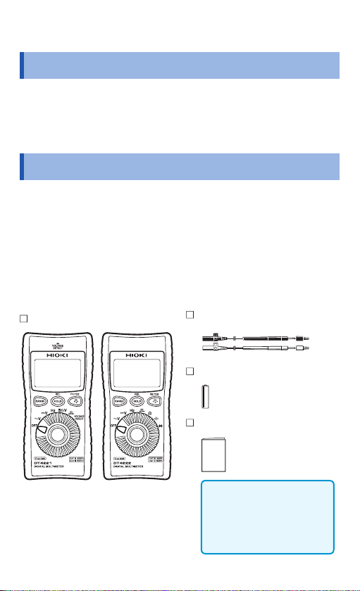
Hioki DT4221 User manual

DT4222
DIGITAL MULTIMETER
DT4221
Instruction Manual
June 2014 Revised edition 1 DT4221A981-01 14-06H
DT4222
DIGITAL MULTIMETER
DT4221
Instruction Manual
June 2014 Revised edition 1 DT4221A981-01 14-06H


i
Contents
Introduction................................................................... 1
Verifying Package Contents ........................................ 1
Options (sold separately) ............................................ 2
Safety Notes.................................................................. 3
Usage Notes.................................................................. 8
1 Overview 11
1.1 Overview and Features........................... 11
1.2 Parts Names and Functions................... 12
1.3 Display ..................................................... 16
1.4 Alarm Display and Battery Indicator ..... 17
2 Preparation for Measurements 19
2.1 Measurement Workflow.......................... 19
2.2 Inserting/Replacing the Battery ............. 20
2.3 Using Test Leads..................................... 22
2.4 Installation in Measurement Location... 25
Hanging the instrument with the strap ................25
3 Performing Measurements 27
3.1 Inspection Before Use ............................ 27
3.2 Measuring Voltage................................... 31
Measuring AC voltage.........................................31
Measuring DC voltage ........................................32
Measurement using the AC and DC
automatic judgment (DT4221) ............................32
3.3 Measuring Frequencies .......................... 33
3.4 Checking Continuity ............................... 34
3.5 Measuring Diode (DT4222) ..................... 35

ii
Contents
3.6 Measuring Resistance (DT4222) ............ 36
3.7 Measuring Electrostatic Capacities
(DT4222) ................................................... 37
3.8 Checking the Electric Charge (DT4221) 38
4 Using Instrument Conveniently 39
4.1 Selecting the Measurement Range........ 39
Measuring with the auto range ...........................39
Measuring with the manual range.......................39
4.2 Retaining the Measured Value ............... 40
4.3 Reducing the Noise (FILTER)................. 41
4.4 Checking the Relative Value/
Performing Zero Adjustment.................. 43
Checking the relative value (REL) ......................43
Performing zero adjustment................................44
4.5 Turning On the Backlight........................ 45
4.6 Using the Auto Power Save (APS)......... 45
4.7 Power-on Option Table ........................... 46
5 Specifications 49
5.1 General Specifications ........................... 49
5.2 Electrical Characteristics ....................... 51
5.3 Accuracy Table........................................ 53
6 Maintenance and Service 59
6.1 Repair, Inspection, and Cleaning........... 59
6.2 Troubleshooting ...................................... 60
6.3 Error Display............................................ 62
Appendix Appx.1
Appx. 1 RMS and Average ....................... Appx.1

1
Introduction
Introduction
Thank you for purchasing the HIOKI DT4221, DT4222 Digital
Multimeter. To obtain maximum performance from the product,
please read this manual first, and keep it handy for future
reference.
Verifying Package Contents
When you receive the instrument, inspect it carefully to ensure
that no damage occurred during shipping.
In particular, check the accessories, panel switches, and
connectors. If damage is evident, or if it fails to operate
according to the specifications, contact your authorized Hioki
distributor or reseller.
Check the package contents as follows.
DT4221 or DT4222
DT4221 DT4222
The holster has been attached.
DT4911 Test Lead (p. 22)
LR03 Alkaline battery × 1
Instruction Manual
(English)
Instruction manuals may
also be available in other
languages.
Please visit our website at
http://www.hioki.com.

2
Options (sold separately)
The following options are available for the instrument. Contact
your authorized Hioki distributor or reseller when ordering.
Connecting cables (p. 22)
L4933
Contact Pin Set
L4934
Small Alligator Clip Set
DT4911
Test Lead
33 V AC/70 V DC
CAT III 300 V/CAT II 600 V
C0200 Carrying Case
The instrument, test leads, instruction manual, and
others can be stored in the case.
Z5004 Magnetic Strap (p. 25)
Attach this strap to the instrument and secure it on
the wall surface such as a metal plate for use.

3
Safety Notes
Safety Notes
This instrument is designed to conform to IEC 61010 Safety
Standards, and has been thoroughly tested for safety prior to
shipment. However, using the instrument in a way not described
in this manual may negate the provided safety features.
Before using the instrument, be certain to carefully read the
following safety notes.
DANGER
Mishandling during use could result in injury or
death, as well as damage to the instrument. Be
certain that you understand the instructions and
precautions in the manual before use.
WARNING
With regard to the electricity supply, there are
risks of electric shock, heat generation, fire, and
arc discharge due to short circuits. If persons
unfamiliar with electricity measuring instruments
are to use the instrument, another person familiar
with such instruments must supervise operations.
Protective gear
WARNING
To avoid electric shock when measuring live
lines, wear appropriate protective gear, such
as insulated rubber gloves, boots and a safety
helmet.

4
Safety Notes
Notation
In this manual, the risk seriousness and the hazard levels are
classified as follows.
DANGER
Indicates an imminently hazardous situation
that will result in death or serious injury to the
operator.
WARNING
Indicates a potentially hazardous situation
that may result in death or serious injury to the
operator.
CAUTION
Indicates a potentially hazardous situation
that may result in minor or moderate injury to
the operator or damage to the instrument or
malfunction.
IMPORTANT
Indicates information related to the operation of
the instrument or maintenance tasks with which
the operators must be fully familiar.
Indicates a high voltage hazard.
If a particular safety check is not performed or
the instrument is mishandled, this may give
rise to a hazardous situation; the operator may
receive an electric shock, may get burnt or may
even be fatally injured.
Indicates a strong magnetic-field hazard.
The effects of the magnetic force can cause
abnormal operation of heart pacemakers and/or
medical electronics.
Indicates prohibited actions.
Indicates the action which must be performed.
*Additional information is presented below.

5
Safety Notes
Symbols affixed to the instrument
Indicates cautions and hazards. When the symbol is printed
on the instrument, refer to a corresponding topic in the
Instruction Manual.
Indicates that dangerous voltage may be present at this
terminal.
Indicates a double-insulated device.
Indicates a grounding terminal.
Indicates DC (Direct Current).
Indicates AC (Alternating Current).
Indicates DC (Direct Current) or AC (Alternating Current).
Symbols for various standards
Indicates the Waste Electrical and Electronic Equipment
Directive (WEEE Directive) in EU member states.
Indicates that the instrument conforms to safety regulations
set out by the EC Directive.
Screen display
This instrument uses the following screen displays.
1234567890
A BCDE FGH I J K LMNOPQR S TUVWXY Z

6
Safety Notes
Accuracy
We define measurement tolerances in terms of rdg. (reading)
and dgt. (digit) values, with the following meanings:
rdg.
(Reading or displayed value)
The value currently being measured and indicated on the
measuring instrument.
dgt.
(Resolution)
The smallest displayable unit on a digital measuring
instrument, i.e., the input value that causes the digital
display to show a “1” as the least significant digit.

7
Safety Notes
Measurement categories
To ensure safe operation of measuring instruments, IEC 61010
establishes safety standards for various electrical environments,
categorized as CAT II to CAT IV, and called measurement
categories.
DANGER
•Using a measuring instrument in an environment
designated with a higher-numbered category
than that for which the instrument is rated
could result in a severe accident, and must be
carefully avoided.
•Using a measuring instrument without
categories in an environment designated with
the CAT II to CAT IV category could result in a
severe accident, and must be carefully avoided.
This instrument conforms to the safety requirements for CAT III 600 V,
CAT IV 300 V measuring instruments.
CAT II: When directly measuring the electrical outlet receptacles of
the primary electrical circuits in equipment connected to an
AC electrical outlet by a power cord (portable tools, household
appliances, etc.)
CAT III: When measuring the primary electrical circuits of heavy equipment
(fixed installations) connected directly to the distribution panel,
and feeders from the distribution panel to outlets
CAT IV: When measuring the circuit from the service drop to the service
entrance, and to the power meter and primary overcurrent
protection device (distribution panel)
T Outlet
CAT II
Internal wiring
Distribution panel
Service entrance
Service drop
CAT IV
Power meter
CAT III
Fixed installation
See: “2.3 Using Test Leads” (p. 22)

8
Usage Notes
Usage Notes
Follow these precautions to ensure safe operation and to obtain
the full benefits of the various functions.
DANGER
If the test lead or the instrument is damaged,
there is a risk of electric shock. Before using the
instrument, perform the following inspection.
•Before using the instrument, check that the
coating of the test leads are neither ripped nor
torn and that no metal parts are exposed. Using
the instrument under such conditions could
result in electrocution. Replace the test leads
with those specified by our company.
•Before using the instrument the first time, verify
that it operates normally to ensure that no
damage occurred during storage or shipping. If
you find any damage, contact your authorized
Hioki distributor or reseller.
Installation
Installing the instrument in inappropriate locations may cause a
malfunction of instrument or may give rise to an accident. Avoid
the following locations.
For details on the operating temperature and humidity, see the
specifications. (p. 49)
CAUTION
• Exposed to direct sunlight or high temperature
• Exposed to corrosive or combustible gases
• Exposed to water, oil, chemicals, or solvents
• Exposed to high humidity or condensation
• Exposed to a strong electromagnetic field or
electrostatic charge
• Exposed to high quantities of dust particles
• Near induction heating systems (such as high-frequency
induction heating systems and IH cooking equipment)
• Susceptible to vibration

9
Usage Notes
Handling the cables
WARNING
To prevent electric shock, when measuring
the voltage of a power line use a test lead that
satisfies the following criteria:
•Conforms to safety standards IEC61010 or
EN61010
•Of measurement category III or IV
•Its rated voltage is higher than the voltage to be
measured
All of the optional test leads for this instrument
conform to the safety standard EN61010. Use
a test lead in accordance with its defined
measurement category and rated voltage.
CAUTION
• Avoid stepping on or pinching the cable, which
could damage the cable insulation.
• To avoid damaging the cables, do not bend or pull
the leads and the probe bases.
The ends of the test leads are sharp. Be careful to
avoid injury.
Precautions during measurement
WARNING
If the instrument is used in locations where the
rating indicated on the instrument or probes
is exceeded, the instrument may be damaged
resulting in personal injury. Do not use the
instrument in such locations.
See “Measurement categories” (p. 7).

10
Usage Notes
CAUTION
• Do not input voltage exceeding the specified
measurement range. Doing so may damage the
instrument.
• During the continuity check, diode test, or
measurement of resistance or electrostatic capacity,
measurement signals are generated in the terminals
of the instrument. Depending on the target for
measurement, the measurement signal may cause
damage.
Seeing “Measurement current” and “Open circuit
voltage” in the accuracy table (p. 53), check, in
advance, that there are no adverse effects of the
measurement current and the open circuit voltage.
Precautions during shipment
Observe the following during shipment. Hioki cannot be
responsible for damage that occurs during shipment.
CAUTION
• During shipment of the instrument, handle it
carefully so that it is not damaged due to a vibration
or shock.
• To avoid damage to the instrument, remove the
accessories and optional equipment from the
instrument before shipment.
If the instrument is not to be used for an extended
period of time
IMPORTANT
To avoid corrosion and/or damage to the instrument due to
battery leakage, remove the battery from the instrument if it is
to be kept in storage for an extended period.

11
1Overview
1.1 Overview and Features
This measuring instrument is a multi-function digital multimeter
that ensures both safety and durability.
Main features and functions
• Speedy display of the RMS measured value
• Environmental performance (can be used anywhere) (Operation
temperature: -10 to 50°C)
• Filter function that controls the influence of noise
• Hold function that retains the screen display
• Solid body which can be used for an extended period of time (drop-
proof)
• Speedy measurement via a fast response (0 V 100 V response
approx. 0.6 seconds*)
* Until the value falls within the accuracy specification range.
Large, easily-
viewable display
Backlighting to allow
users to read the
measurement values in
dark environments
Problem finding a suitable
installation location?
The strap with magnet allows
the instrument to be hung
conveniently.
For various
purposes
The measurement
test leads and end
pins can be selected.

13
Parts Names and Functions
Operation keys
1
1
2
2
3
3
Normal
Pressed down
for at least 1
second
Power-on
option (p. 46)
1
1Sets the manual
range/switches
the range.
Cancels the manual
range.
All LCDs
light up and
the software
version is
displayed.
RANGE:AUTO / RANGE:MANUAL
2
2Manually sets/
cancels the hold
function for the
displayed value.
Sets/cancels the
display of the
relative value
(REL).
Cancels the
auto power save
function (APS).
lights up/
goes off.
lights up/goes
off.
APS goes off.
3
3Turns on/off the
backlight.
Switches/cancels
the low pass filter
and passband
settings.
Turns off the
automatic
backlight
deactivation.

14
Parts Names and Functions
Rotary switches and measurement descriptions
7
7
8
8
9
9
DT4221 DT4222
1
1
1
1
3
3
4
4
5
5
6
6
2
2
5
5
2
2
3
3
Function DT4221 DT4222
1
1
2
2AC voltage measurement
DC voltage measurement
3
3Frequency measurement
4
4DC/AC voltage measurement
(Automatic judgment)
Input impedance 900k±20%
-
5
5Continuity check
6
6Electrical charge measurement -
7
7Resistance measurement -
8
8Electrostatic capacity
measurement
-
9
9Diode test -

15
Parts Names and Functions
Rear
DT4221
12
1
1
2
2
Test lead holder
The test lead can be held.
2
2
2
Strap hole
The optional Z5004 Magnetic Strap
can be attached. (p. 25)
Battery cover
When replacing the battery (p. 20),
remove the cover.
(See p. 20)
Serial number label
It is necessary for production control
such as product warranty.
Do not peel off the label.
Measurement terminals (See p. 24)
1
1The red test lead is connected. Hereafter referred to as “V
terminal”.
2
2The black test lead is connected. Hereafter referred to as “COM
terminal”.

16
Display
1.3 Display
For error displays, see “6.3 Error Display” (p.62).
56789
10
11
1
2
4
3
1
1AC, DC
automatic
judgment*1
2
2AC, DC
3
3Continuity check
(p.34)
4
4Diode (p. 35)
5
5
Retention of the
measured value
(p. 40)
6
6Relative value
display (p. 43)
7
7
The filter function
is activated.
(p. 41)
8
8
The auto power
save function
is activated.
(p. 45)
9
9
Battery indicator
(p. 17)
10
10
Indication (example): In the
case of 30 V input in the 60 V
range, the bar is displayed to
the center of the scale.
11
11
Auto range, manual range
(p. 39)
*1: DT4221
Other manuals for DT4221
1
This manual suits for next models
1
Table of contents
Other Hioki Multimeter manuals