4
_____________________________________________________________________________________________
1.4 Installing the RS-232C Interface
_____________________________________________________________________________________________
WARNING To avoid electric shock accident, before removing or replacing an
input module, confirm that the instrument is turned off and that the
power cord and connection cables are disconnected.
The mounting screws must be firmly tightened or the input unit may
not perform to specifications, or may even fail.
To avoid the danger of electric shock, never operate the product
with an input module removed. To use the product after removing
an input module, install a blank panel over the opening of the
removed module.
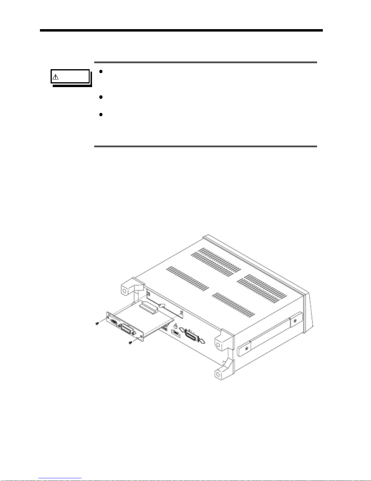
1.4 Installing the RS-232C Interface
The space for fitting the 9593-01 RS-232C INTERFACE in the rear panel of
the 3532-50/3522-50 are covered with a blanking plate. Follow these three
steps to install the 9593-01 interface:
1. Remove the fixing screws, and take off the blanking plate.
2. Insert the 9593-01 RS-232C INTERFACE into the exposed slot in the rear
of the unit in the figure below.
3. Push the 9593-01 firmly into place, and fix with the screws removed in
step 1.