4
────────────────────────────────────────────────────
1.4 Installing the GP-IB Interface
────────────────────────────────────────────────────
WARNIN
To prevent electrical shock, before adding or replacing the GP-IB
interface, check that the power for the unit is off and the power cord
and connectors are disconnected. [The fixing screws must be firmly
tightened or the input unit may not function up to specification, or may
even fail.]
To avoid the danger of electric shock, never operate the unit with a
GP-IB interface removed. If you should wish to use the unit after
removing an interface, fit a blank panel over the opening of the removed
unit.
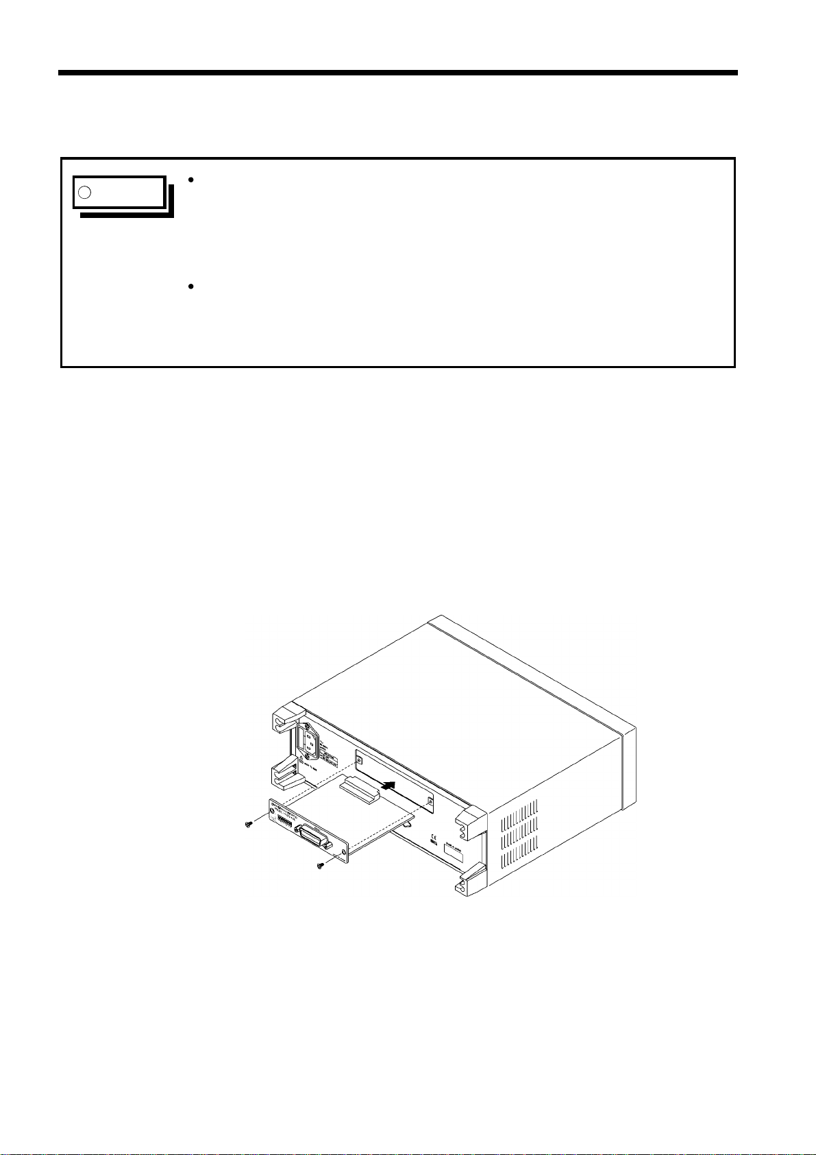
.4 Installing the GP-IB Interface
The space for fitting the 9518-02 GP-IB INTERFACE in the rear panel of the
3157 is covered with a blank panel. Follow these three steps to install the
9518-02 interface:
(1) Remove the fixing screws, and take off the blank panel.
(2) Insert the 9518-02 GP-IB INTERFACE into the exposed slot in the rear of
the unit in the figure below.
(3) Push the 9518-02 firmly into place, and fix with the screws removed in
step 1.