Hirose BM10 Series User manual

1
0.4mm Contact Pitch,Stacking Height 0.8mm Board-to-Board /Board-to-FPC Connectors
BM10 Series
2022.2
■Features
1.Higher density of the board-mounted
components
Extremely small board mounting pattern and low above the-
board profile makes the connectors ideally suited for small
device applications.
Globally unrivalled compact depth :when mated 2.98mm
Header 2.46mm
Length - world’s smallest class :10.4mm
2.Reliable electrical and mechanical connection
Despite its small mated height, unique contact configuration,
with a 2-point contacts and effective mating length of
0.2mm(height 0.8mm), assures highly reliable connection while
confirming a complete mating with a definite tactile feel.
3.Large self-alignment distance
The connectors will self-align within 0.3 mm.
4.Built-in shock absorbing feature
The protrusions and indents in the insulator bodies protect the
connectors from failures when exposed to sudden impact.
5.Solder wicking prevention
Nickel barriers prevent un-intentional solder wicking.
6.Contamination protection
Insulator walls protect the contact areas against flux splatter or
other physical particles contamination.
7.Conducive traces on the PCB can run under
the connector
No exposed contacts on the bottom of the connector.
8dciVXiVgZVhVgZcdiZmedhZYidi]Zdjih^YZ
eZcZigVi^dcd[i]Z[ajmdgdi]Zge]nh^XVaeVgi^XaZh#
8dciVXiVgZVh
8dciVXiVgZVh
Decrease in the board-occupied area
High contact reliability
Splatter protection
figure.1
figure.2
figure.3
BM10Series:P=0.4mm, H=0.8mm 40pos.
Other HRS connector
P=0.4mm, H=0.9mm
2.98×10.4
= 30.99mm2
4.56×10.22
= 46.60mm2
10.22mm
10.4mm
2.98mm
4.56mm
Conventional connector BM10
BM10
33.5%
saving of space
Headercontact
Receptaclecontact
Maincontact
point
Auxiliarylock
point
Mar.1.2022Copyright2022HIROSEELECTRICCO.,LTD.AllRightsReserved.

2
BM10 Series●0.4mm Contact Pitch,Stacking Height 0.8mm Board-to-Board /Board-to-FPC Connectors
■Specifications
Ratings
Current rating
0.3A
Operating
temperature range -35°C to +85°C (Note 1) Storage
temperature range
-10°C to +60°C (Note 2)
Voltage rating
30V AC, DC Operating
humidity range RH 20% to 80% Storage
humidity range
RH 40% to 70% (Note 2)
Item Specification Conditions
1.Insulation resistance 50Mø min 100V DC
2.Withstanding voltage
No flashover or insulation breakdown 100V AC / 1minute
3.Contact resistance 100mø max. 20mV AC, 1kHz, 1mA
4.Vibration No electrical discontinuity of 1µs or longer
No damage or parts dislocation
Frequency : 10 to 55 Hz, 5min, single amplitude of 0.75
mm, 10cycles, for each directions.
5.Humidity Contact resistance : 100mø max.,
Insulation resistance : 25Mø min.
96hours at 40 ±2°C and humidity of 90 to 95%
No damage or parts dislocation
6.Temperature cycle
Contact resistance : 100mø max.,
Insulation resistance : 50Mø min.
No damage or parts dislocation
-55°C ➝5 to 35°C ➝85°C ➝5 to 35°C
Time : 30min. ➝10min. ➝30min. ➝10min.
5cycles
7.Durability Contact resistance : 100mø max. 10cycles
8.Resistance to
soldering heat No deformation of components affecting performance Reflow : At the recommended temperature profile
Manual soldering : 350°C for 3 seconds
Note 1 : Includes temperature rise caused by current flow.
Note 2 : The term "storage" here refers to products stored for a long period prior to board mounting and use.
The operating temperature and humidity range covers the non-conducting condition of connectors after board mounting and the
temporary storage conditions of transportation, etc.
Note 3 : Information contained in this catalog represents general requirements for this Series. Contact us for the drawings and specifications
for a specific part number shown.
■Material
Product Part Material Finish Remarks
Receptacle Insulator LCP Color:Black UL94V-0
Header Contacts Phosphor bronze Gold plated ---------
■Ordering information
●Receptacles / Headers
BM 10 # (0.8)−*DS − 0.4 V (**)
❶❷❸❹ ❺❻ ❼❽ ❾
❻Connector style
DS : Double-row receptacle
DP : Double-row header
❼Contact pitch : 0.4mm
❽
Termination type V…SMT vertical mount
❾Packaging
(51) : Embossed tape packaging (8,000 pieces per reel)
(53) : Embossed tape packaging (1,000 pieces per reel)
❶Series name : BM
❷Series No. : 10
❸Configuration
B : With mettal fittings
NB : With mettal fittings
❹Stacking Height : 0.8mm
❺Number of contacts.10 to 60
Mar.1.2022Copyright2022HIROSEELECTRICCO.,LTD.AllRightsReserved.

3
BM10 Series●0.4mm Contact Pitch,Stacking Height 0.8mm Board-to-Board /Board-to-FPC Connectors
■H=0.8mm Receptacles (With metal fittings)
■Recommended PCB mounting pattern
All dimensions : mm
Part Number HRS No.
Number of Contacts
ABCDEF
BM10NB(0.8)-10DS-0.4V(51) 684-6100-0 51 10 4.4 1.6 0.8 3.1 2.18 4.02
BM10NB(0.8)-16DS-0.4V(51) 684-6110-4 51 16 5.6 2.8 1.6 4.3 3.38 5.22
BM10NB(0.8)-20DS-0.4V(51) 684-6105-4 51 20 6.4 3.6 1.6 5.1 4.18 6.02
BM10NB(0.8)-24DS-0.4V(51) 684-6101-3 51 24 7.2 4.4 2 5.9 4.98 6.82
BM10NB(0.8)-30DS-0.4V(51) 684-6106-7 51 30 8.4 5.6 2 7.1 6.18 8.02
BM10NB(0.8)-34DS-0.4V(51) 684-6108-2 51 34 9.2 6.4 2.4 7.9 6.98 8.82
BM10NB(0.8)-40DS-0.4V(51) 684-6107-0 51 40 10.4 7.6 2.4 9.1 8.18 10.02
BM10NB(0.8)-44DS-0.4V(51) 684-6109-5 51 44 11.2 8.4 2.8 9.9 8.98 10.82
BM10NB(0.8)-50DS-0.4V(51) 684-6102-6 51 50 12.4 9.6 2.8 11.1 10.18 12.02
BM10NB(0.8)-60DS-0.4V(51) 684-6103-9 51 60 14.4 11.6 3.2 13.1 12.18 14.02
Note 1 : Order by number of reels.
Note 2 : This connector is NOT polarized.
B±0.02
P=0.4±0.02
0.23±0.02
F+0.05
0
E0
-0.05
3.44 +0.05
0
2.34 0
-0.05
2.34 0
-0.05
3.28 +0.05
0
0.08
2.64
Pickandplacearea:C
2.98
2.9
P=0.4
A
B
0.8
D
Mar.1.2022Copyright2022HIROSEELECTRICCO.,LTD.AllRightsReserved.

4
BM10 Series●0.4mm Contact Pitch,Stacking Height 0.8mm Board-to-Board /Board-to-FPC Connectors
■Headers (With metal fittings)
■Recommended metal mask dimensions
All dimensions : mm
Part Number HRS No.
Number of Contacts
ABCDEF
BM10B(0.8)-10DP-0.4V(51) 684-6007-5 51 10 3.32 1.6 0.8 2.74 2.3 3.18
BM10B(0.8)-16DP-0.4V(51) 684-6047-0 51 16 4.52 2.8 1.6 3.94 3.5 4.38
BM10B(0.8)-20DP-0.4V(51) 684-6009-0 51 20 5.32 3.6 1.6 4.74 4.3 5.18
BM10B(0.8)-24DP-0.4V(51) 684-6011-2 51 24 6.12 4.4 2 5.54 5.1 5.98
BM10B(0.8)-30DP-0.4V(51) 684-6013-8 51 30 7.32 5.6 2 6.74 6.3 7.18
BM10B(0.8)-34DP-0.4V(51) 684-6015-3 51 34 8.12 6.4 2.4 7.54 7.1 7.98
BM10B(0.8)-40DP-0.4V(51) 684-6003-4 51 40 9.32 7.6 2.4 8.74 8.3 9.18
BM10B(0.8)-44DP-0.4V(51) 684-6039-1 51 44 10.12 8.4 2.8 9.54 9.1 9.98
BM10B(0.8)-50DP-0.4V(51) 684-6017-9 51 50 11.32 9.6 2.8 10.74 10.3 11.18
BM10B(0.8)-60DP-0.4V(51) 684-6001-9 51 60 13.32 11.6 3.2 12.74 12.3 13.18
Note 1 : Order by number of reels.
Note 2 : This connector is NOT polarized.
P=0.4
B
A
2.46
1.8
1.62
0.08
0.15
D
0.63
0.08
Pickandplacearea:C
0.23±0.02
P=0.4±0.02
B±0.02
F+0.05
0
0
-0.05
E
0
-0.05
0.8
1.98+0.05
0
2.76 +0.05
0
1.28 0
-0.05
Mar.1.2022Copyright2022HIROSEELECTRICCO.,LTD.AllRightsReserved.

5
BM10 Series●0.4mm Contact Pitch,Stacking Height 0.8mm Board-to-Board /Board-to-FPC Connectors
●Receptacle (24 and above positions)
■Embossed CarrierTape Dimensions
●Receptacle (less than 24 positions)
JcgZZa^c\Y^gZXi^dc
:;;
;";
6¤%#(
7¤%#&
%#(¤%#&
&#%*¤%#&*
:":
&#,*¤%#&
:
)¤%#&'¤%#&-¤%#&
¢&#*
%#&
%
;";
;;:
6¤%#(
7¤%#&
(¤%#&
&#%*¤%#&*
:":
&#,*¤%#&
:
)¤%#&'¤%#&-¤%#&
¢&#*
%#&
%
JcgZZa^c\Y^gZXi^dc
Mar.1.2022Copyright2022HIROSEELECTRICCO.,LTD.AllRightsReserved.

6
BM10 Series●0.4mm Contact Pitch,Stacking Height 0.8mm Board-to-Board /Board-to-FPC Connectors
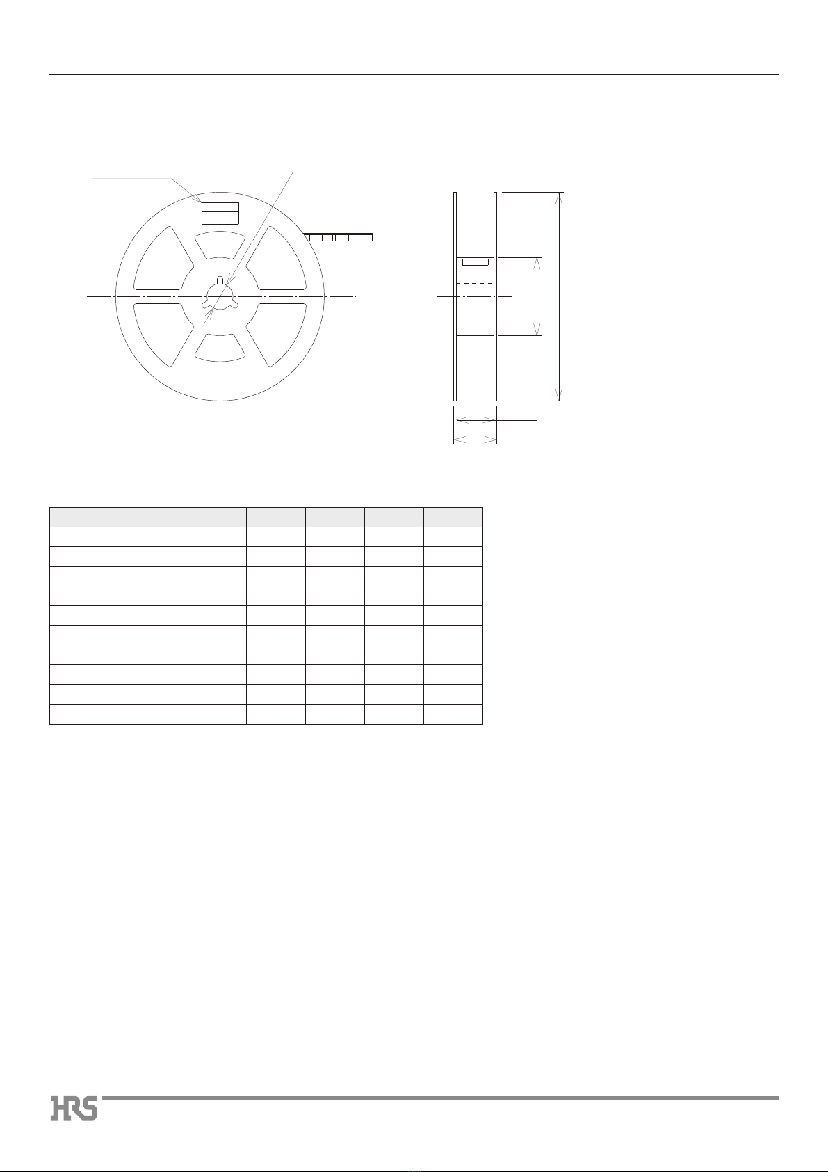
■Reel dimensions (Receptacles)
EVgicjbWZgaVWZa
¢&(¤%#'
9¤&
8¤%#*
¢(-%¤'
¢-%¤&
Unit : mm
Part Number A B C D
BM10#(0.8)-10DS-0.4V(51) 16 7.5 17.5 21.5
BM10#(0.8)-16DS-0.4V(51) 16 7.5 17.5 21.5
BM10#(0.8)-20DS-0.4V(51) 16 7.5 17.5 21.5
BM10#(0.8)-24DS-0.4V(51) 16 7.5 17.5 21.5
BM10#(0.8)-30DS-0.4V(51) 24 11.5 25.5 29.5
BM10#(0.8)-34DS-0.4V(51) 24 11.5 25.5 29.5
BM10#(0.8)-40DS-0.4V(51) 24 11.5 25.5 29.5
BM10#(0.8)-44DS-0.4V(51) 24 11.5 25.5 29.5
BM10#(0.8)-50DS-0.4V(51) 24 11.5 25.5 29.5
BM10#(0.8)-60DS-0.4V(51) 24 11.5 25.5 29.5
Mar.1.2022Copyright2022HIROSEELECTRICCO.,LTD.AllRightsReserved.

7
BM10 Series●0.4mm Contact Pitch,Stacking Height 0.8mm Board-to-Board /Board-to-FPC Connectors
●Header
JcgZZa^c\Y^gZXi^dc ;";
;;
:
')¤%#(
&&#*¤%#&
¢&#*
%#&
%
)¤%#&'¤%#&-¤%#&
)
*
%#(¤%#&
%#-¤%#&*
:":
&#,*¤%#&
:
Mar.1.2022Copyright2022HIROSEELECTRICCO.,LTD.AllRightsReserved.
8
BM10 Series●0.4mm Contact Pitch,Stacking Height 0.8mm Board-to-Board /Board-to-FPC Connectors
■Reel dimensions (Header)
EVgicjbWZgaVWZa
¢&(¤%#'
9¤&
8¤%#*
¢(-%¤'
¢-%¤&
Unit : mm
Part Number A B C D
BM10#(0.8)-10DP-0.4V(51) 12 5.5 13.5 17.5
BM10#(0.8)-16DP-0.4V(51) 16 7.5 17.5 21.5
BM10#(0.8)-20DP-0.4V(51) 16 7.5 17.5 21.5
BM10#(0.8)-24DP-0.4V(51) 16 7.5 17.5 21.5
BM10#(0.8)-30DP-0.4V(51) 16 7.5 17.5 21.5
BM10#(0.8)-34DP-0.4V(51) 16 7.5 17.5 21.5
BM10#(0.8)-40DP-0.4V(51) 24 11.5 25.5 29.5
BM10#(0.8)-44DP-0.4V(51) 24 11.5 25.5 29.5
BM10#(0.8)-50DP-0.4V(51) 24 11.5 25.5 29.5
BM10#(0.8)-60DP-0.4V(51) 24 11.5 25.5 29.5
Mar.1.2022Copyright2022HIROSEELECTRICCO.,LTD.AllRightsReserved.
9
BM10 Series●0.4mm Contact Pitch,Stacking Height 0.8mm Board-to-Board /Board-to-FPC Connectors
■Usage Recommendations
Manual soldering : 340±10ç for 3 seconds
Header, Receptacle : Thickness 0.12mm
: Open area ratio 100%
* When using nitrogen-reflow, 75% only at the header side.
Maximum of 0.02mm at the connector center, with both ends of the
connector as reference points.
Cleaning is not recommended.
If you clean this product, please evaluate its performance before using it.
(Cleaning may impair the mating/unmating properties and lower
resistance to environmental factors.)
■
Be careful when mating/unmating the connector when it is not mounted
on the PCB as it may cause damage/deformation to contacts.
■Avoid supporting the PCB only with the connectors.
Support it by other means such as bolts, screws, posts, etc.
■Excessive prying during unmating/mating may result in damage.
■In the case of hand soldering, please do not apply any flux which
could cause flux wicking.
■This product may have slight color differences due to production
lot variability, but this does not affect the performance.
■Please refer to the following page for handling precautions when
inserting and removing.
■Because the product can disengage if dropped (or other impact),
or by FPC routing, it is advised to secure the mated connectors
to the board with housings and cushioning materials
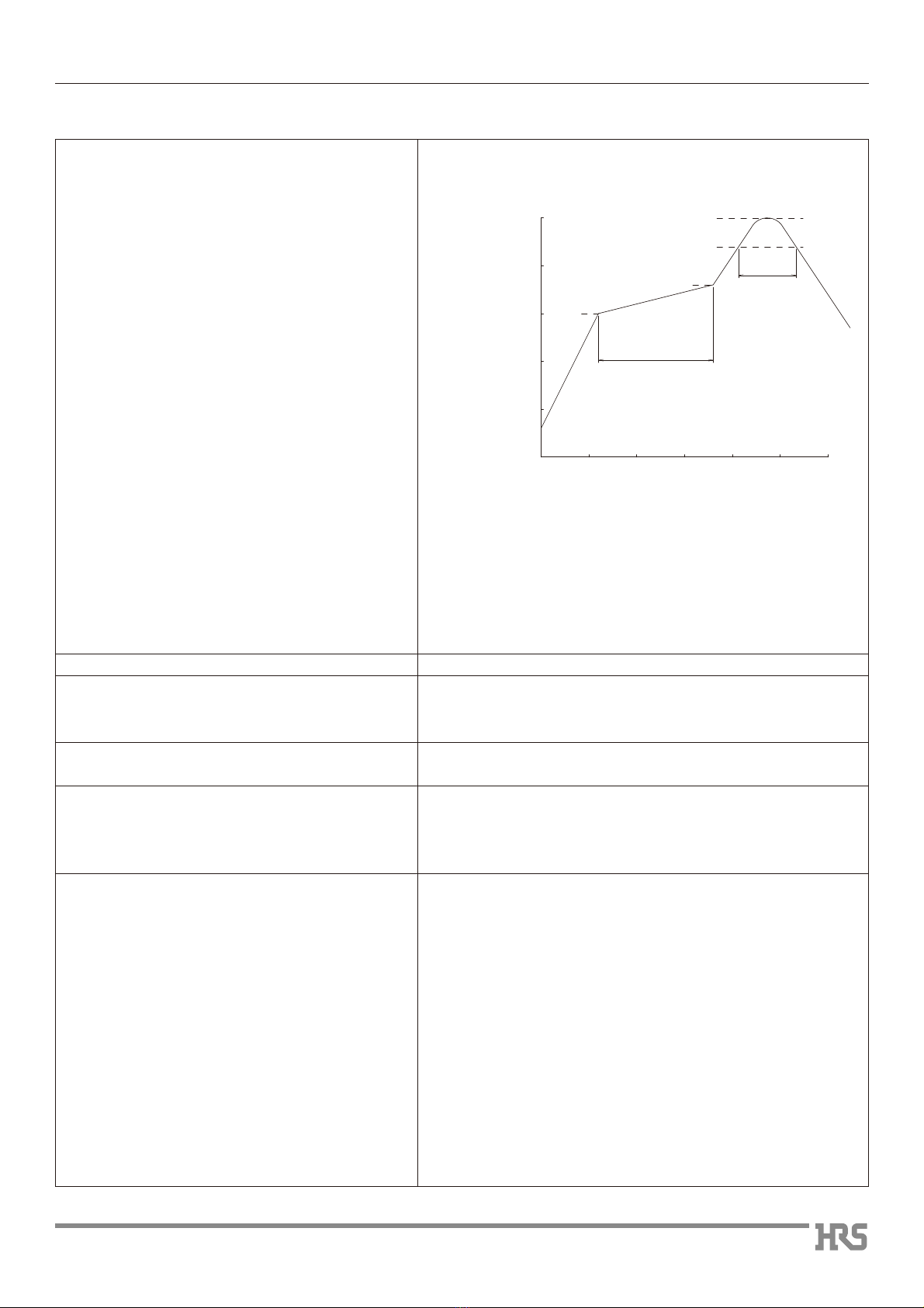
Note 1: Up to 2 cycles of Reflow soldering are possible under the
same conditions, provided that there is a return to normal
temperature between the first and second cycle.
Note 2 : The temperature profile indicates the board surface
temperature at the point of contacts with the connector
terminals.
*%
+%hZXbVm
&%%
&*%
'%%
'*%
I^bZhZX#
IZbeZgVijgZ
%&%% &*% '%% '*%*%
GddbiZbeZgVijgZ
(%%
.%s&'%hZX
&-%
'*%
''%
&*%
1.Recommended temperature profile
2.Recommended manual soldering
3.Recommended screen thickness and open
area ratio (Pattern area ratio)
4.Board warpage
5.Cleaning conditions
6.Precautions
Mar.1.2022Copyright2022HIROSEELECTRICCO.,LTD.AllRightsReserved.
10
BM10 Series●0.4mm Contact Pitch,Stacking Height 0.8mm Board-to-Board /Board-to-FPC Connectors
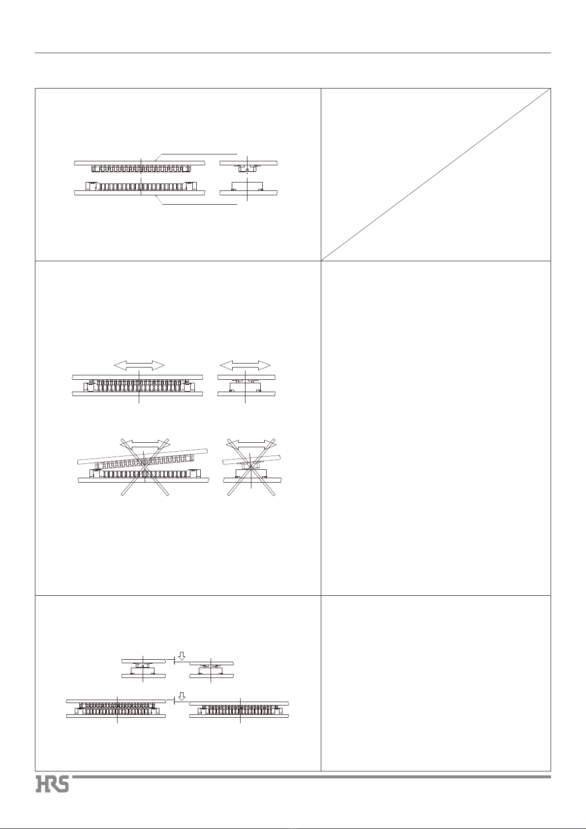
■Handling Precautions when Mating Connectors
Keep the connectors parallel to each other
when positioning. The connectors will self-
align in horizontal directions.
Do not attempt to mate the connectors starting
at one end or side.
Press-down even until fully mated.
BM10*(0.8)-*DP-0.4V
BM10*(0.8)-*DS-0.4V
Mar.1.2022Copyright2022HIROSEELECTRICCO.,LTD.AllRightsReserved.
11
BM10 Series●0.4mm Contact Pitch,Stacking Height 0.8mm Board-to-Board /Board-to-FPC Connectors
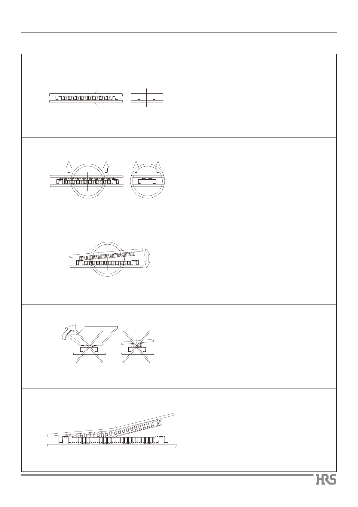
Fully mated
Lift even, keeping both connectors parallel to
each other
When handling, circumstances may prevent
the connectors from being kept parallel when
un-mating. One end may be lifted as shown.
However, to use this procedure the connector
must be mounted on sufficiently rigid circuit
board.
Any deflection of the board during this
operation may result in damage to the
connector or solder joints.
Do not attempt to start the un-mating of the
connectors from one side or corner.
Failure to exercise caution when un-mating
the connectors mounted on the non-rigid FPC
may also result in connector breakage.
It is the responsibility of the user to perform
verification of the repeated mating / un-mating
cycles with the connectors mounted on the
applicable FPC.
When the rigidity of the FPC is low, there is a
risk that the connector could break as
illustrated in the diagram at left.
Please use the connectors after performing a
check of repeated operation with the FPC that
the customer will be using.
Evaluative results of FPC rigidity and various
items are available. Please inquire.
E^iX]dg^ZciVi^dc
8dgcZgdg^ZciVi^dc L^Yi]dg^ZciVi^dc
■CHandling PrecautionsWhen Un-mating Connectors
BM10*(0.8)-*DS-0.4V
BM10*(0.8)-*DP-0.4V
Mar.1.2022Copyright2022HIROSEELECTRICCO.,LTD.AllRightsReserved.

12
BM10 Series●0.4mm Contact Pitch,Stacking Height 0.8mm Board-to-Board /Board-to-FPC Connectors
2-6-3,Nakagawa Chuoh,Tsuzuki-Ku,Yokohama-Shi 224-8540,JAPAN
https://www.hirose.com/
MEMO:
The characteristics and the specifications contained herein are for reference purpose. Please refer to the latest customer drawings prior to use.
The contents of this catalog are current as of date of 02/2022. Contents are subject to change without notice for the purpose of improvements.
Mar.1.2022Copyright2022HIROSEELECTRICCO.,LTD.AllRightsReserved.
Table of contents
Other Hirose Cables And Connectors manuals

Hirose
Hirose GT16G-1S-HU User manual

Hirose
Hirose GT43 User manual

Hirose
Hirose DF53 Series Manual

Hirose
Hirose FH63 Series Manual
 User manual")
Hirose
Hirose DF62WZ-6P-2.2DSA(20) User manual

Hirose
Hirose GT16GM Series User manual

Hirose
Hirose HIF Series User manual

Hirose
Hirose DF62W Series Manual

Hirose
Hirose BM56G Series Instruction Manual

Hirose
Hirose EnerBee DF60 Series User manual


