manuals.online logo
Brands
  1. Home
  2. •
  3. Brands
  4. •
  5. Hirose
  6. •
  7. Cables And Connectors
  8. •
  9. Hirose DF62WZ-6P-2.2DSA(20) User manual

Hirose DF62WZ-6P-2.2DSA(20) User manual

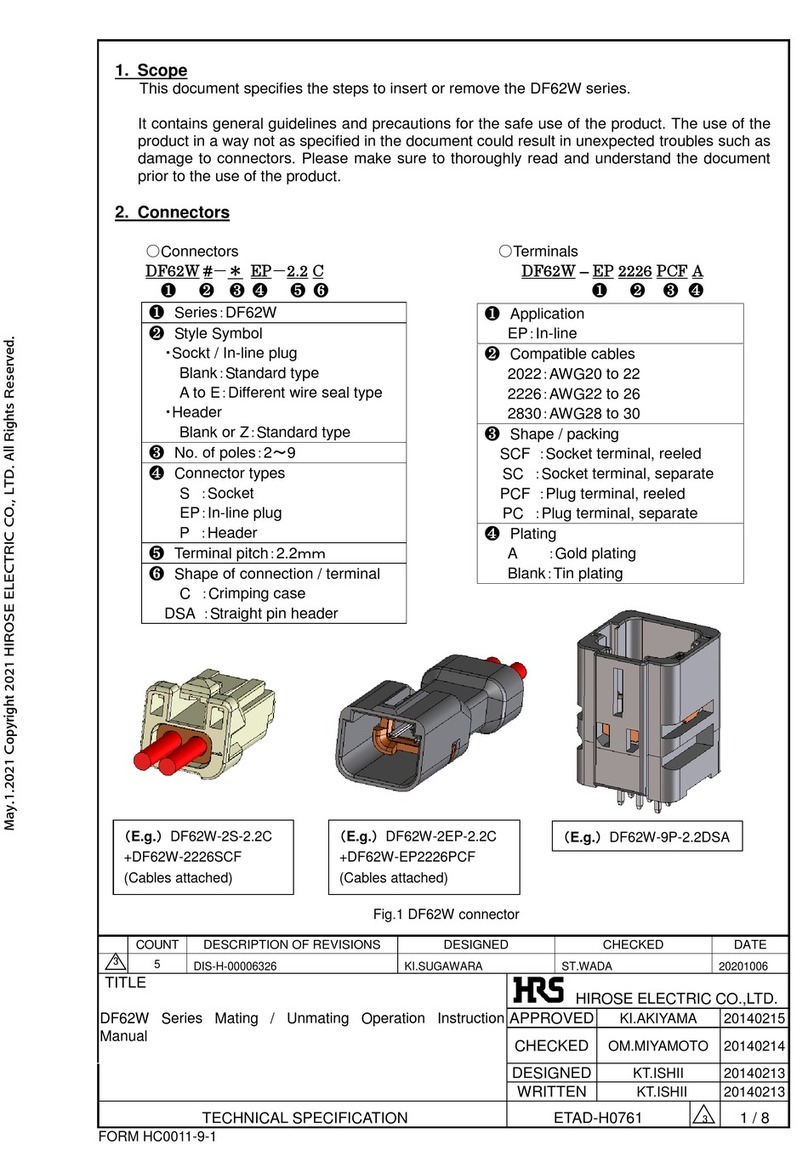
1. Scope
This document specifies the steps to insert or remove the DF62W series.
It contains general guidelines and precautions for the safe use of the product. The use of the
product in a way not as specified in the document could result in unexpected troubles such as
damage to connectors. Please make sure to thoroughly read and understand the document
prior to the use of the product.
2. Connectors
○Connectors ○Terminals
DF62W #-* EP-2.2 C DF62W –EP 2226 PCF A
❶❷❸❹❺❻❶❷❸❹
❶Application
EP:In-line
❷Compatible cables
2022:AWG20 to 22
2226:AWG22 to 26
2830:AWG28 to 30
❸Shape / packing
SCF :Socket terminal, reeled
SC :Socket terminal, separate
PCF :Plug terminal, reeled
PC :Plug terminal, separate
❹Plating
A :Gold plating
Blank:Tin plating
❶Series:DF62W or DF62WZ
❷Style Symbol
・Sockt / In-line plug
Blank:Standard type
A to E:Different wire seal type
・Header
Blank or Z:Standard type
❸No. of poles:2~9
❹Connector types
S:Socket
EP:In-line plug
P:Header
❺Terminal pitch:2.2mm
❻Shape of connection / terminal
C:Crimping case
DSA :Straight pin header
COUNT
DESCRIPTION OF REVISIONS
DESIGNED
CHECKED
DATE
4
1
DIS-H-00018787
KI.SUGAWARA
HT.SATO
20230809
TITLE
DF62W Series Mating / Unmating Operation Instruction
Manual
APPROVED
KI.AKIYAMA
20140215
CHECKED
OM.MIYAMOTO
20140214
DESIGNED
KT.ISHII
20140213
WRITTEN
KT.ISHII
20140213
TECHNICAL SPECIFICATION
ETAD-H0761-00
4
1 / 8
FORM HC0011-9-1
HIROSE ELECTRIC CO.,LTD.
(E.g.)DF62W-2S-2.2C
+DF62W-2226SCF
(Cables attached)
(E.g.)DF62W-2EP-2.2C
+DF62W-EP2226PCF
(Cables attached)
Fig.1 DF62W connector
(E.g.)DF62W-9P-2.2DSA
4
HIROSE ELECTRIC CO.,LTD.
ETAD-H0761-00
4
2 / 8
FORM HC0011-9-2
○Connectors(Panel waterproof type)
DF62WP-*/*/*/*EP-2.2 C
❶❷❸❹❺
❶Series:DF62WP
❷No. of poles:2~9
“/” Indicates that the connector
is a composite connector with a
number of poles separated by it.
❸Connector types
EP:In-line plug
❹Terminal pitch:2.2mm
❺Shape of connection / terminal
C:Crimping case
Fitting surface:Front
(E.g.)DF62WP-3/4/6/2EP-2.2C
+DF62W-EP2226PCF(Cables attached)
Lock: Upper
3芯
4芯
6芯
2芯
Fig.2 DF62WP connector
* The order of the number of poles in
the product name is from the left side
when the lock hole is on the upper side
and the fitting hole is on the front side.
HIROSE ELECTRIC CO.,LTD.
ETAD-H0761-00
4
3 / 8
FORM HC0011-9-2
3. Operation procedure
3-1. Insertion
3-1-a. Positioning for insertion:
Adjust the position for insertion according to the locks of the socket and
In-line plug or header.
The mating combination of the socket and In-line plug is shown below.
3-1-b. Insertion:
Adjust the position for insertion according to the locks of the socket and
In-line plug or header.
The mating combination of Socket and In-line plug is shown below.
Fig.4 Insertion
Direction of insertion
Fig.3 Positioning for insertion
Socket lock
In-line plug lock
HIROSE ELECTRIC CO.,LTD.
ETAD-H0761-00
4
4 / 8
FORM HC0011-9-2
To avoid degraded quality, do not tilt the socket for insertion as shown in the
figure above.
Do not perform mating (different pole mating) between different numbers of poles as
there is a risk of terminal buckling and terminal disconnection.
Especially when using the DF62WP series (Panel waterproof type), carefully check the
arrangement of the number of poles and be careful not to perform different pole fitting.
Fig.5 Prohibited insertion
Figure 6. Prohibition insertion method (different pole fitting)
Socket:2Pin
Plug:3Pin
HIROSE ELECTRIC CO.,LTD.
ETAD-H0761-00
4
5 / 8
FORM HC0011-9-2
3-1-c. Check fitting:
Make sure the socket has been firmly fit with the In-line plug or header.
(Check that the socket lock has been caught at the In-line plug or header lock
either visually or by slightly pulling a cable by hand.)
To remove the socket, see 3-2. Socket removal.
The mating combination of Socket and In-line plug is shown below.
3-2. Socket removal
3-2-a. Removal:
Remove the socket while pressing with a finger the lock spring on the socket to unlock.
The mating combination of Socket and In-line plug is shown below.
Note:To prevent the lock hanger from being damaged or the cables from being
disconnected, do not remove the socket when it is locked.
* Breaking strength of lock is approx. 30 N when connector is pulled in straight
direction. Please avoid excessive force is applied to the connector.
* Retention force is approx. 7 N / Pin. Please avoid excessive force is applied to
particular cable.
Fig.7 Check fitting
Fig.8 Socket removal
Socket lock hanger
In-line plug lock hanger
Direction of removal
Lock spring
HIROSE ELECTRIC CO.,LTD.
ETAD-H0761-00
4
6 / 8
FORM HC0011-9-2
To avoid degraded quality , do not tilt the socket for removal as shown in the figure above.
Fig.9 Profibited removal removal
HIROSE ELECTRIC CO.,LTD.
ETAD-H0761-00
4
7 / 8
FORM HC0011-9-2
4. Notes
Do not insert or remove the socket while electrifying.
Excessive external force applied to connectors could cause failure or damage. Therefore,
avoid forced insertion or removal, dropping impact, cable wiring (pull, twist) and such.
During cable wiring inside the machine, keep sufficient cable length for slack to avoid direct
stress is applied to the connector.
Forcible wiring such as bending the cable near the connector and straining the cable, could
cause contact failure and / or waterproof defect.
Check with the cable manufacturer for cable flexibility.
●Cable bending
When bending the cable, provide a straight part from the end face of the connector as
shown in the figure below and bend it.
(It depends on the flexibility of the cable, but please bend it at the position of 30 mm as a
guide.)
Do not bend sharply from the end face of the connector or stretch the base of the cable
because it will put a load on the terminal contact part and the terminal crimping part
and cause contact failure and waterproof failure.
Sudden bending, tense bending
Straight
Figure 5-1. Cable bending
Min:30mm
Min:30mm
Bending with a straight
part
Min:30mm
Min:30mm
HIROSE ELECTRIC CO.,LTD.
ETAD-H0761-00
4
8 / 8
FORM HC0011-9-2
Sudden bending, tense bending
Bending with a straight
part
Figure 5-2. Cable bending (DF62WP)
Straight
Min:30mm
Min:30mm
Min:30mm
Min:30mm

This manual suits for next models

4

Other Hirose Cables And Connectors manuals
Hirose DF62W Series Manual

Hirose

Hirose DF62W Series Manual

Hirose FH63 Series Manual

Hirose

Hirose FH63 Series Manual

Hirose HIF Series User manual

Hirose

Hirose HIF Series User manual

Hirose DF53 Series Manual

Hirose

Hirose DF53 Series Manual

Hirose GT43 User manual

Hirose

Hirose GT43 User manual

Hirose GT50 Series User manual

Hirose

Hirose GT50 Series User manual

Hirose GT16GM Series User manual

Hirose

Hirose GT16GM Series User manual

Hirose EnerBee DF60 Series User manual

Hirose

Hirose EnerBee DF60 Series User manual

Hirose GT16G-1S-HU User manual

Hirose

Hirose GT16G-1S-HU User manual

Hirose BM56G Series Instruction Manual

Hirose

Hirose BM56G Series Instruction Manual

Hirose EnerBee DF60 Series User manual
Hirose

Hirose EnerBee DF60 Series User manual
Hirose BM10 Series User manual

Hirose

Hirose BM10 Series User manual

Popular Cables And Connectors manuals by other brands
Emerson Rosemount 356 Reference manual

Emerson

Emerson Rosemount 356 Reference manual

WEST POS-124-U-PFN Technical documentation

WEST

WEST POS-124-U-PFN Technical documentation

Simplified MFG RSP1:2 manual

Simplified MFG

Simplified MFG RSP1:2 manual

Sensio Gamma SE988950 quick start guide

Sensio

Sensio Gamma SE988950 quick start guide

Lenze L-force EYF 0021 A F03 Series Mounting instructions

Lenze

Lenze L-force EYF 0021 A F03 Series Mounting instructions

Klein Tools VDV110-295 manual

Klein Tools

Klein Tools VDV110-295 manual

CYP PU-1H7HBTPL Operation manuals

CYP

CYP PU-1H7HBTPL Operation manuals

Paradyne 5030 installation instructions

Paradyne

Paradyne 5030 installation instructions
Panduit KMTRTH installation instructions
Panduit

Panduit KMTRTH installation instructions

Ugo UHU-1009 USB HUB UGO 6-PORT user manual

Ugo

Ugo UHU-1009 USB HUB UGO 6-PORT user manual

ADC Category 5e Specification sheet

ADC

ADC Category 5e Specification sheet

AAVARA PS124 installation guide

AAVARA

AAVARA PS124 installation guide

RIDGID SeeSnake NanoReel Operator's manual

RIDGID

RIDGID SeeSnake NanoReel Operator's manual

enphase CT-200-SOLID Quick install guide

enphase

enphase CT-200-SOLID Quick install guide

SeaLevel VERSA COMM+4/EX user manual

SeaLevel

SeaLevel VERSA COMM+4/EX user manual

nvent Raychem IEK-25-PIPE installation instructions
nvent

nvent Raychem IEK-25-PIPE installation instructions
Logan SX-SP06S operating instructions

Logan

Logan SX-SP06S operating instructions

ATEN VS1814T user manual

ATEN

ATEN VS1814T user manual

manuals.online logo
manuals.online logoBrands
  • About & Mission
  • Contact us
  • Privacy Policy
  • Terms and Conditions

Copyright 2025 Manuals.Online. All Rights Reserved.