Hirose FH63 Series Manual

1
2017.8②
0.5mm Pitch, 2.8mm high, Single Action Lock at bottom contact point, FPC/FFC/Shield FFC connector
FH63 Series
Fig.3
Robust lock firmly retains FPC/FFC.
GND contact and FFC GND plate
contact at multiple points.
Matedcondition
(correctposition)
Insufficientinsertioncondition
(incorrectposition)
21.94mm
5.15mm
Single action lock (Dimension diagram : 30pos.)
Fig.1
Fig.2
FPC FFC Shield FFC
Shield FFC
GND contact
Two-point contact design for dust prevention
Fig.4Fig.5
Supports FPC/FFC/Shield FFC
High FPC retention force
FPC/FFC can be checked from the top surface after mating.
OK NG
Shielded FFC is acceptable for EMI prevention.
Insert FPC/FFC without opening
the lock lever before insertion!
2.8mm
■Features
1. Automatic single action locking design
· Single action locking by simply inserting FPC after mounting
contributes to enhanced workability. (Fig.1)
(Lock release by operating the lock lever when removing.)
· Operation of the lock lever is not required at the time of
mating FPC. Can be inserted with one hand.
Contributes to reduced assembly time.
The lock lever will not be damaged by operation.
Mating failure is reduced by eliminating the need to operate
a lever while mating.
2.
Two-points of contact prevents contact failure by dust
· High contact reliability by independent spring two-point
contact design, preventing contact failure by dust. (Fig.2)
3. Supports FPC/FFC/Shield FFC
· FH63 allows you to choose from FPC/FFC/Shield FFC.
· Shielded FFC is acceptable for EMI prevention.(Fig.3)
4. High FPC retention force
· The circuit is automatically locked after FPC/FFC is inserted
by a single action. The notches on both sides of FPC are
held by the lock lever, generating a high FPC retention
force in spite of the small contact. (Fig.4)
5.
Visual inspection on the mated status of FPC/FFC is possible.
· As the notches on both sides of FPC can be checked from
the top surface after inserting FPC/FFC, insufficient
insertion during assembly is prevented. (Fig.5)
6. Environmental
· Halogen free
*AS defined by IEC 61249-2-21.
Br : 900ppm max, Cl : 900ppm max, Br+Cl : 1,500ppm
max
Mar.1.2018 Copyright 2018 HIROSE ELECTRIC CO., LTD. All Rights Reserved.

2
FH63 Series●0.5mm Pitch, 2.8mm high, Single Action Lock at bottom contact point, FPC/FFC/Shield FFC connector
Series name : FH
Series No. : 63
No. of contacts : 30
Contact pitch : 0.5mm
Terminal type
SH …SMT horizontal mounting type
Specification
Blank : Standard 3,500pcs/reel
(99) : 500pcs/reel
FH 63 − 30S − 0.5 SH (99)
❹❺ ❻
■Product Specifications
Rating
Rated current 0.5A
Rated voltage 50V AC/DC rms
Operating temperature range : -55ç to +105°C (Note 1)
Operating humidity range : Relative humidity 90% max.
(No condensation)
Storage temperature range : -10ç to +60°C (Note 2)
Storage humidity range : Relative humidity 90% max.
(No condensation)
Adaptive FPC
contact specifications
Thickness : = 0.33 ± 0.03mm Signal layout : Gold plated, GND plate : Tin plated
Item Specification Conditions
1.
Insulation resistance
500Mømin. 100V DC
2.
Withstanding voltage
No flashover or insulation breakdown 150V AC rms / 1 minute
3. Contact
resistance
100mø max.
* Including FPC/FFC conductor resistance 1mA AC
4. Durability
(insertion / withdrawal)
Contact resistance : 100mø max.
No damage, cracks, or parts dislocation 10 cycles
5. Vibration
No electrical discontinuity of 1µs or more
Contact resistance : 100mø max.
No damage, cracks, or parts dislocation
Frequency : 10 to 55Hz, single amplitude of 0.75mm,
10 cycles in each of the 3 directions
6. Shock
No electrical discontinuity of 1µs or more
Contact resistance : 100mø max.
No damage, cracks, or parts dislocation
Acceleration of 981m/s2, duration of 6 ms, sine half-wave
waveform, 3 cycles in each of the 3 axes
7.
Damp heat
(Steady state)
Contact resistance : 100mø max.
Insulation resistance : 50Mø min.
No damage, cracks, or parts dislocation
96 hours at temperature of 60ç and humidity of 90% to
95%
8.
Temperature
cycle
Contact resistance : 100mø max.
Insulation resistance : 50Mø min.
No damage, cracks, or parts dislocation
Temperature: -55°C /+15ç to +35ç /+105ç /+15ç to +35ç
Time : 30 / 2 to 3 / 30 /2 to 3 (Minutes)
5 cycles
9. Resistance to
soldering heat
No deformation of components affecting
performance
Reflow : Recommended Temperature Profile
Manual soldering: 350 ± 10°C for 5 seconds
Note 1 : Includes temperature rise caused by current flow.
Note 2 : The term “storage” refers to products stored for long period of time prior to mounting and use. Operating Temperature Range
and Humidity Range covers non-conducting condition of installed connectors in storage, shipment or during transportation.
■Materials / Finish
Part Materials Finish UL standard
Insulator LCP Grey UL94V-0
LCP Black UL94V-0
Signal contact Copper alloy Nickel barrier gold plated ---------------
Grounding contact Copper alloy Pure tin reflow plated ---------------
Reinforcing metal tabs SUS Pure tin reflow plated ---------------
■Product Number Structure
Refer to the chart below when determining the product specifications from the product number.
Please select from the product numbers listed in this catalog when placing orders.
Mar.1.2018 Copyright 2018 HIROSE ELECTRIC CO., LTD. All Rights Reserved.

3
FH63 Series●0.5mm Pitch, 2.8mm high, Single Action Lock at bottom contact point, FPC/FFC/Shield FFC connector
■Connector Dimensions
Unit : mm
Part No. HRS No. No. of
Contacts ABCDEFG
FH63-10S-0.5SH Under planning (Note 1) 10 12.7 4.5 5.55 4 2 7.15 9.9
FH63-20S-0.5SH Under planning (Note 1) 20 17.7 9.5 6.55 9 1.5 12.15 14.9
FH63-30S-0.5SH 580-4400-0 ** 30 22.7 14.5 5.55 14 2 17.15 19.9
FH63-40S-0.5SH 580-4403-0 ** 40 27.7 19.5 10.55 19 1.5 22.15 24.9
FH63-50S-0.5SH Under planning (Note 1) 50 32.7 24.5 15.55 24 2 27.15 29.9
FH63-60S-0.5SH Under planning (Note 1) 60 37.7 29.5 20.55 29 1.5 32.15 34.9
Note 1 : Contact positions without HRS No. are currently under planning.
Please contact hirose for detailed information about product variation.
HRS mark
G±0.15
(0.65)
(F)
0.5±0.1
(0.25)
2.8±0.2
4.9±0.1
(C)
2±0.1 E±0.1
4.5±0.1
(3.3)
(0.1)
a
(0.1)
3
2
5
4
1
D±0.15
E±0.1
A±0.15
B±0.15
Signal contact No.1
Polarity mark
Grounding contact No.1
Grounding contact No.2
(Pickup area)
Cavity No.
Reinforcing
metal tabs
(Lead of reinforcing metal tabs)
Signal
contact
Grounding
contact
(Signal contact lead)
(Grounding contact lead)
Signal
contactpoint
Ground
contact point
(5.3)
0.55±0.1 4.25±0.2
(0.89)
(5.15)
(0.42)
(0.87)
(2.85)
(2.4)
0.75±0.1
0.35±0.1
3.9±0.2
(4)0.25±0.2
0.25±0.2
(2.2)
(45°)
FPC/FFC/Shield FFC t=0.33
Note
1 : The dimension in parentheses are for reference.
2 : Lead co-planarity including reinforced chucking metals shall be 0.1 max.
3 : To be delivered with tape and reel packages.
See the packaging specifications for details.
4 : Note that preventive hole for sink mark or slit could be added for improvement.
5 : The quality remains good, even with the dark spots, which could occasionally occur on molded plastic.
6 : This product satisfies halogen free requirements defined as 900ppm maximum chlorine,
900ppm maximum bromine, and 1500ppm maximum total of chlorine and bromine.
Mar.1.2018 Copyright 2018 HIROSE ELECTRIC CO., LTD. All Rights Reserved.
4
FH63 Series●0.5mm Pitch, 2.8mm high, Single Action Lock at bottom contact point, FPC/FFC/Shield FFC connector
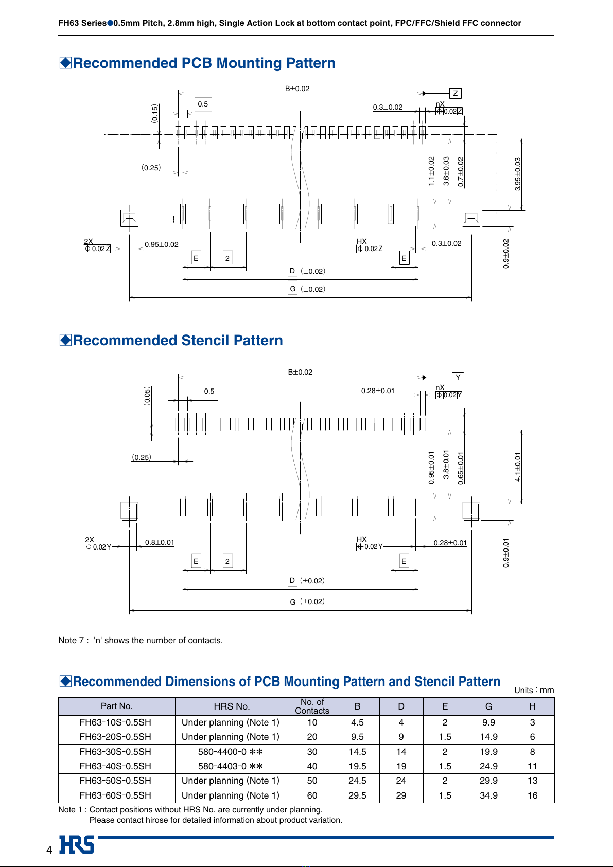
BRecommended PCB Mounting Pattern
B
Recommended Dimensions of PCB Mounting Pattern and Stencil Pattern
BRecommended Stencil Pattern
Units:mm
Part No. HRS No. No. of
Contacts BDEGH
FH63-10S-0.5SH Under planning (Note 1) 10 4.5 4 2 9.9 3
FH63-20S-0.5SH Under planning (Note 1) 20 9.5 9 1.5 14.9 6
FH63-30S-0.5SH 580-4400-0 ** 30 14.5 14 2 19.9 8
FH63-40S-0.5SH 580-4403-0 ** 40 19.5 19 1.5 24.9 11
FH63-50S-0.5SH Under planning (Note 1) 50 24.5 24 2 29.9 13
FH63-60S-0.5SH Under planning (Note 1) 60 29.5 29 1.5 34.9 16
Note 1 : Contact positions without HRS No. are currently under planning.
Please contact hirose for detailed information about product variation.
E
B±0.02
(0.25)
0.3±0.02
HX
0.02Z
0.7±0.02
3.6±0.03
1.1±0.02
0.3±0.02
0.9±0.02
3.95±0.03
G
D
2
0.95±0.02
E
0.5
(0.15)
(±0.02)
(±0.02)
nX
0.02 Z
Z
2X
0.02 Z
(0.05)
E
0.8±0.01
2
D
4.1±0.01
0.9±0.01
0.28±0.01
0.95±0.01
3.8±0.01
0.65±0.01
0.28±0.01
(0.25)
B±0.02
0.5
E
G
(±0.02)
(±0.02)
2X
0.02Y
HX
0.02Y
nX
0.02Y
Y
Note 7 : 'n' shows the number of contacts.
Mar.1.2018 Copyright 2018 HIROSE ELECTRIC CO., LTD. All Rights Reserved.

5
FH63 Series●0.5mm Pitch, 2.8mm high, Single Action Lock at bottom contact point, FPC/FFC/Shield FFC connector
BRecommended FPC/FFC Dimensions
BRecommended Shield FFC Dimensions
R0.2
R0.1±0.1
R0.1±0.1
R0.2
R0.2
R0.2
R0.2
B±0.02
(K)
4.75±0.3
4.15±0.1
2.9±0.1
1.25±0.1
L±0.1
J±0.05
1.3±0.07
1.3±0.07
0.8±0.05
0.5 0.4±0.03
1.3±0.07
1.3±0.07
0.8±0.05
J±0.05
1 MIN (overlapping amount)
6 MIN (Reinforcing film)
0.33±0.03
nX
0.02 X
X
R0.2
R0.1±0.1
R0.1±0.1
R0.2
R0.2
R0.2
R0.2
0.8±0.05
0.8±0.05
4.75±0.1
4.15±0.1
2.9±0.1
1.25±0.1
L±0.1
J±0.05
0.32±0.03
1.3±0.08 1.3±0.08
1.3±0.08
1.3±0.08
0.5
B±0.05
(K)
J±0.05
1 MIN (overlapping amount)
6 MIN (Reinforcing film)
0.33±0.03
Grounding plate
Shield
1.1±0.3
(M)
1.1±0.3
0.5±0.3
nX
0.05
W
W
BRecommended Dimensions of FPC/FFC/Shield FFC Units:mm
Part No. HRS No. No. of
Contacts BJKLM
FH63-10S-0.5SH Under planning (Note 1) 10 4.5 7.1 5.5 9.1 4.9
FH63-20S-0.5SH Under planning (Note 1) 20 9.5 12.1 10.5 14.1 9.9
FH63-30S-0.5SH 580-4400-0 ** 30 14.5 17.1 15.5 19.1 14.9
FH63-40S-0.5SH 580-4403-0 ** 40 19.5 22.1 20.5 24.1 19.9
FH63-50S-0.5SH Under planning (Note 1) 50 24.5 27.1 25.5 29.1 24.9
FH63-60S-0.5SH Under planning (Note 1) 60 29.5 32.1 30.5 34.1 29.9
Note 1 : Contact positions without HRS No. are currently under planning.
Please contact hirose for detailed information about product variation.
Note 7 : The value 'n' indicates the number of pos.
Overlap the shield on the grounding plate.
8
Mar.1.2018 Copyright 2018 HIROSE ELECTRIC CO., LTD. All Rights Reserved.
6
FH63 Series●0.5mm Pitch, 2.8mm high, Single Action Lock at bottom contact point, FPC/FFC/Shield FFC connector
B
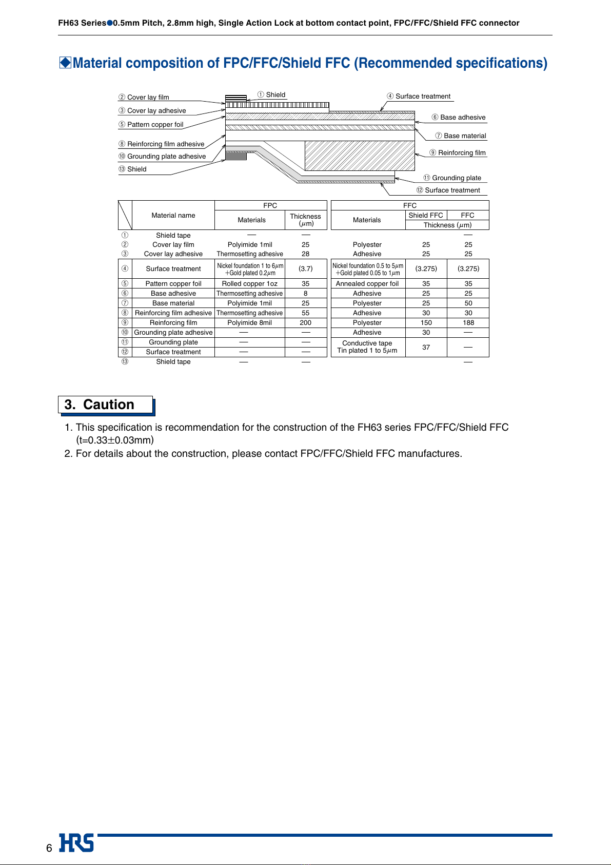
Material composition of FPC/FFC/Shield FFC (Recommended specifications)
FPC FFC
②Cover lay film ①Shield
③Cover lay adhesive
⑤Pattern copper foil
⑧Reinforcing film adhesive
⑩Grounding plate adhesive
⑬Shield
Nickel foundation 1 to 6μm
+Gold plated 0.2μm
Nickel foundation 0.5 to 5μm
+Gold plated 0.05 to 1μm
Materials Shield FFC FFC
Materials
Thickness
(μm) Thickness (μm)
Material name
①
②
③
④
⑤
⑥
⑦
⑧
⑨
⑩
⑪
⑫
⑬
Shield tape
Cover lay film
Cover lay adhesive
Surface treatment (3.7)
Pattern copper foil
Base adhesive
Base material
Reinforcing film adhesive
Reinforcing film
Grounding plate adhesive
Grounding plate
Surface treatment
Shield tape
Polyester
Adhesive
Annealed copper foil
Adhesive
Polyester
Adhesive
Polyester
Adhesive
Conductive tape
Tin plated 1 to 5μm
Polyimide 1mil
Thermosetting adhesive
Rolled copper 1oz
Thermosetting adhesive
Polyimide 1mil
Thermosetting adhesive
Polyimide 8mil
25
28
35
8
25
55
200
(3.275)
25
25
35
25
25
30
150
30
37
(3.275)
25
25
35
25
50
30
188
⑪Grounding plate
⑫Surface treatment
⑨Reinforcing film
⑦Base material
⑥Base adhesive
④Surface treatment
3. Caution
1.
This specification is recommendation for the construction of the FH63 series FPC/FFC/Shield FFC
(t=0.33±0.03mm)
2. For details about the construction, please contact
FPC/FFC/Shield FFC
manufactures.
Mar.1.2018 Copyright 2018 HIROSE ELECTRIC CO., LTD. All Rights Reserved.

7
FH63 Series●0.5mm Pitch, 2.8mm high, Single Action Lock at bottom contact point, FPC/FFC/Shield FFC connector
P±0.3
R±0.1
(2)
4±0.1
8±0.1
1.75±0.1
(3)
6
7
9
(0.3)
Ø1.5
+0.1
0
Unreeling
direction
(0.3)
(3)
1.75±0.1
8±0.1
4±0.1
(2)
R±0.1
Q±0.1
P±0.3
6
7
9
Ø1.5
+0.1
0
Unreeling
direction
●Embossed Carrier Tape Dimensions
●Reel Dimensions
tape width 24mm or less tape width 32mm or less
●Leader, Trailer Dimensions
BPackaging Specifications
Unit : mm
Part No. HRS No. No. of
Contacts PQRSU
FH63-10S-0.5SH Under planning (Note 1) 10 24 ---- 11.5 29.4 25.4
FH63-20S-0.5SH Under planning (Note 1) 20 32 28.4 14.2 37.4 33.4
FH63-30S-0.5SH 580-4400-0 ** 30 44 40.4 20.2 49.4 45.4
FH63-40S-0.5SH 580-4403-0 ** 40 44 40.4 20.2 49.4 45.4
FH63-50S-0.5SH Under planning (Note 1) 50 56 52.4 26.2 61.4 57.4
FH63-60S-0.5SH Under planning (Note 1) 60 56 52.4 26.2 61.4 57.4
Note 1 : Contact positions without HRS No. are currently under planning.
Please contact hirose for detailed information about product variation.
U±1 (Reel inner width)
Unreeling
direction
S±1 (Reel outer width)
8
Ø380±2
Ø80±1
(Ø13)
160mmMIN
Embossedcarriertape
(Trailer,emptycomponents)
Topcovertape
400mmMIN(Leader)
Unreeling direction
100mmMIN
(emptycomponents)
Note 9 : 3500 pieces shall be packaged in one reel. (For standard products)
Note 10 : The package complies with JIS C 0806 and IEC 60286-3 (Packaging of automotive mounting parts).
Mar.1.2018 Copyright 2018 HIROSE ELECTRIC CO., LTD. All Rights Reserved.

8
FH63 Series●0.5mm Pitch, 2.8mm high, Single Action Lock at bottom contact point, FPC/FFC/Shield FFC connector
BTemperature Profile
MAX 250℃
start
25℃60 to 90 sec.
20 to 40 sec.
120±5 sec.
Preheating time Soldering time
Peak temperature
0
50
100
150 150℃
180℃
220℃
200
245
Temperature(℃)
Time(sec.)
Applicable Conditions
Reflow method : IR/Hot air
Reflow environment : Room air
Solder : Paste type Sn/3.0Ag/0.5Cu
(M705-GRN360-K2-V made by Senju
Metal Industry Co.)
Test PCB : PCB material and size
Glass epoxy 45×25×1mm
Land size, per recommended on page 4.
Metal mask : Thickness and opening size
Per recommended on page 4.
This temperature profile is based on the above conditions.
It may vastly depending on solder paste type, manufacturer,
PCB size and mounting materials. Please use only after
checking the mounting conditions.
Mar.1.2018 Copyright 2018 HIROSE ELECTRIC CO., LTD. All Rights Reserved.
9
FH63 Series●0.5mm Pitch, 2.8mm high, Single Action Lock at bottom contact point, FPC/FFC/Shield FFC connector
BConnector operation and points to note
[Operation method]
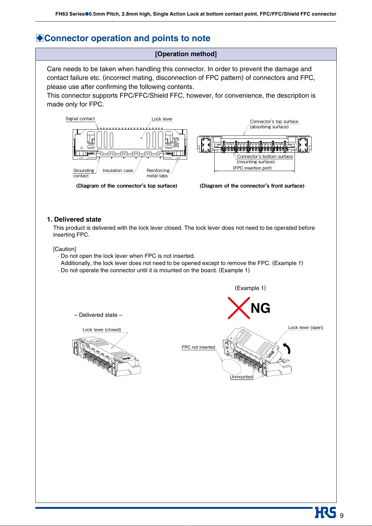
Care needs to be taken when handling this connector. In order to prevent the damage and
contact failure etc. (incorrect mating, disconnection of FPC pattern) of connectors and FPC,
please use after confirming the following contents.
This connector supports FPC/FFC/Shield FFC, however, for convenience, the description is
made only for FPC.
1. Delivered state
This product is delivered with the lock lever closed. The lock lever does not need to be operated before
inserting FPC.
[Caution]
· Do not open the lock lever when FPC is not inserted.
Additionally, the lock lever does not need to be opened except to remove the FPC. (Example 1)
· Do not operate the connector until it is mounted on the board. (Example 1)
(FPC insertion port)
Signalcontact
Grounding
contact
Insulationcase Reinforcing
metaltabs
Locklever Connector'stopsurface
(absorbingsurface)
Connector'sbottomsurface
(mountingsurface)
FPC not inserted
Locklever(closed) Locklever(open)
Unmounted
NG
(Diagramoftheconnector'stopsurface) (Diagramoftheconnector'sfrontsurface)
(Example 1)
– Delivered state –
Mar.1.2018 Copyright 2018 HIROSE ELECTRIC CO., LTD. All Rights Reserved.
10
FH63 Series●0.5mm Pitch, 2.8mm high, Single Action Lock at bottom contact point, FPC/FFC/Shield FFC connector
BConnector operation and points to note
[Operation method]
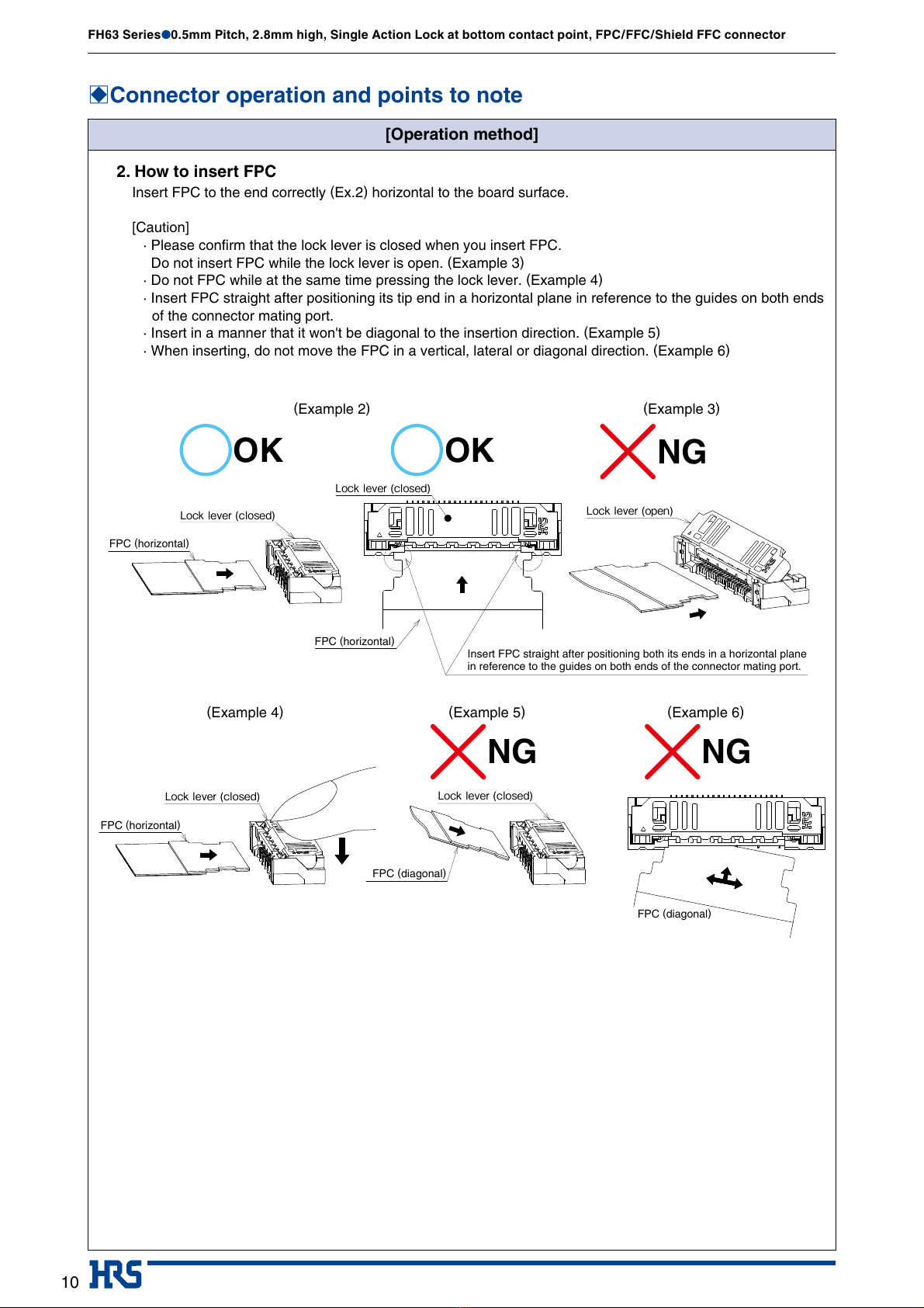
2. How to insert FPC
Insert FPC to the end correctly (Ex.2) horizontal to the board surface.
[Caution]
· Please confirm that the lock lever is closed when you insert FPC.
Do not insert FPC while the lock lever is open. (Example 3)
· Do not FPC while at the same time pressing the lock lever. (Example 4)
· Insert FPC straight after positioning its tip end in a horizontal plane in reference to the guides on both ends
of the connector mating port.
· Insert in a manner that it won't be diagonal to the insertion direction. (Example 5)
· When inserting, do not move the FPC in a vertical, lateral or diagonal direction. (Example 6)
FPC (horizontal)
FPC (horizontal)
Insert FPC straight after positioning both its ends in a horizontal plane
in reference to the guides on both ends of the connector mating port.
Locklever(open)
Locklever(closed)
Locklever(closed)
FPC (horizontal)
FPC (diagonal)
FPC (diagonal)
Locklever(closed) Locklever(closed)
OK OK
NGNG
NG
(Example 2)
(Example 4) (Example 5) (Example 6)
(Example 3)
Mar.1.2018 Copyright 2018 HIROSE ELECTRIC CO., LTD. All Rights Reserved.

11
FH63 Series●0.5mm Pitch, 2.8mm high, Single Action Lock at bottom contact point, FPC/FFC/Shield FFC connector
BConnector operation and points to note
[Operation method]
3. Confirming the mated state of FPC
When FPC is completely inserted, visually inspect the inserted status of FPC. (Example 7)
(This connector uses the lock protrusion of the lock lever for positioning FPC.)
[Caution]
· FPC is not inserted deep enough or in a diagonal direction. (Example 8)(Example 9)
· Because of the single action lock, The lever does not need to be operated after inserting FPC.
FPC (shallow) FPC (diagonal)
FPC
FPC is inserted diagonally, and
leaves a large gap between FPC
and the housing.
FPC is not inserted deep enough,
leaving a large gap between FPC
and the housing.
The protrusion of the lock lever
runs over the FPC tab.
The protrusion of the lock lever
runs over the FPC tab.
Outer shape of FPC is
parallel to the outer
shape of the housing.
FPC is inserted diagonally,
and is not inserted to the
back of the mating port.
FPC is not inserted deep
enough down to the back
of the mating port.
The FPC tab inserted to
the back of the mating port
can be visually confirmed.
Case butting position Case butting position Case butting position
NGNG
OK
(Example 7) (Example 8) (Example 9)
– Cross section of the lock section – – Cross section of the lock section – – Cross section of the lock section –
Mar.1.2018 Copyright 2018 HIROSE ELECTRIC CO., LTD. All Rights Reserved.
12
FH63 Series●0.5mm Pitch, 2.8mm high, Single Action Lock at bottom contact point, FPC/FFC/Shield FFC connector
BConnector operation and points to note
[Operation method]
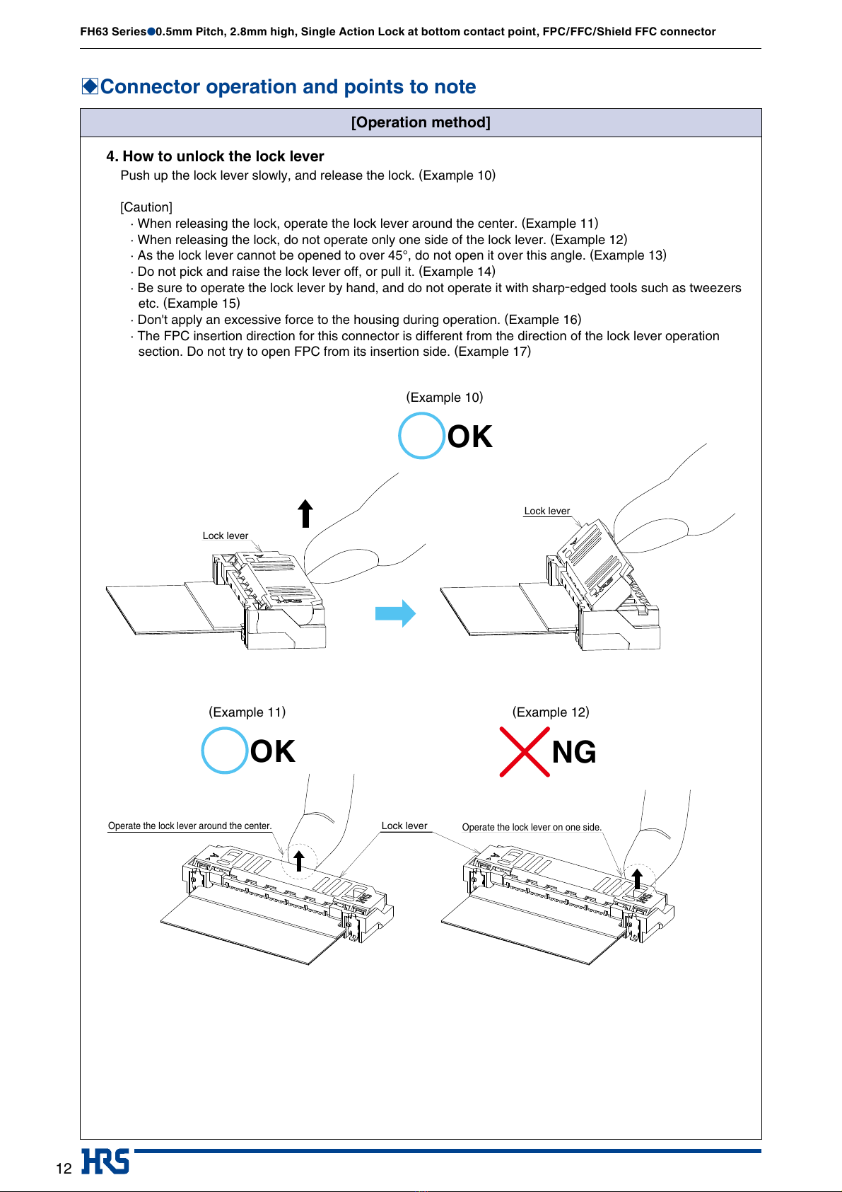
4. How to unlock the lock lever
Push up the lock lever slowly, and release the lock. (Example 10)
[Caution]
· When releasing the lock, operate the lock lever around the center. (Example 11)
· When releasing the lock, do not operate only one side of the lock lever. (Example 12)
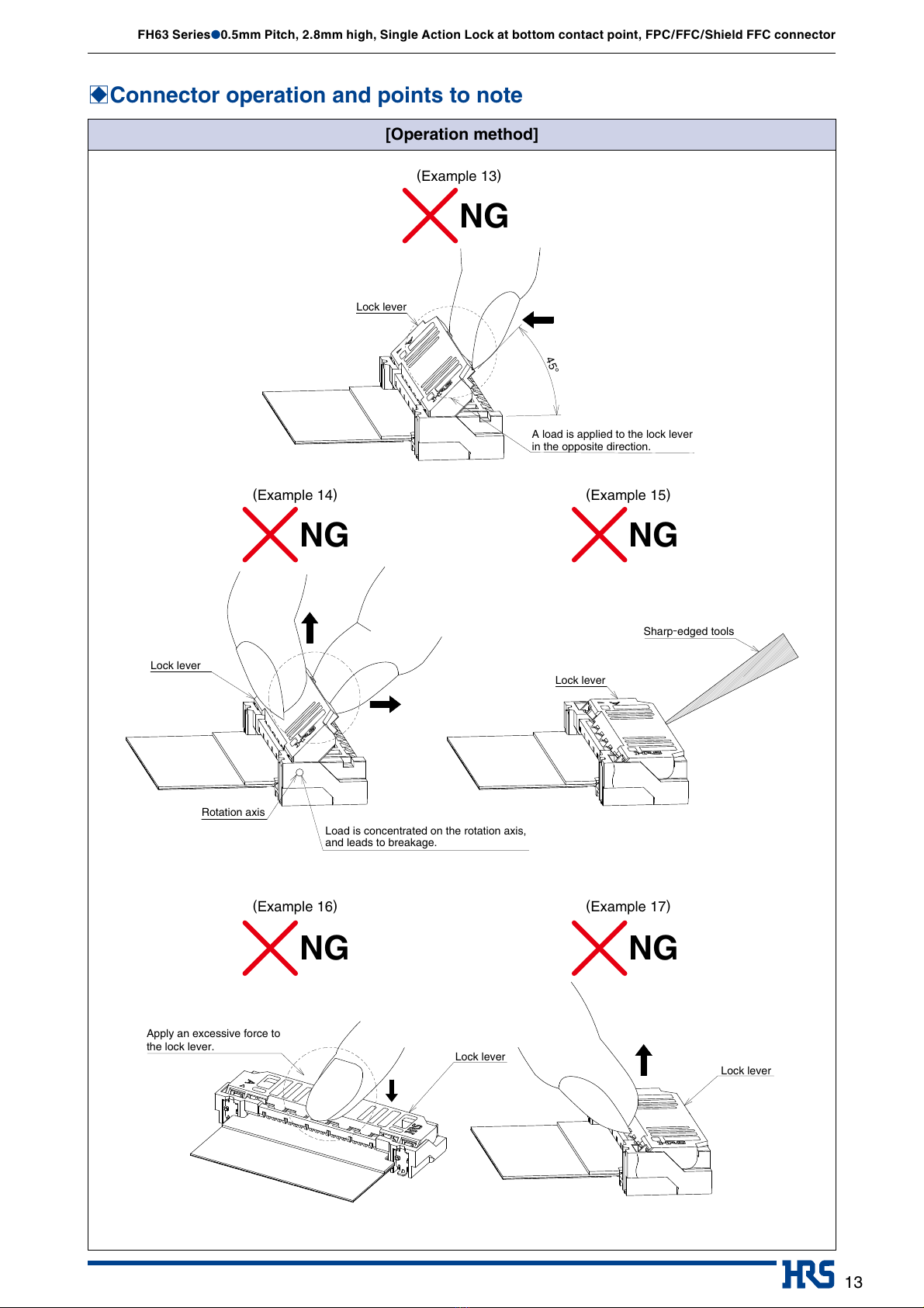
· As the lock lever cannot be opened to over 45°, do not open it over this angle. (Example 13)
·Do not pick and raise the lock lever off, or pull it. (Example 14)
· Be sure to operate the lock lever by hand, and do not operate it with sharp-edged tools such as tweezers
etc. (Example 15)
· Don't apply an excessive force to the housing during operation. (Example 16)
· The FPC insertion direction for this connector is different from the direction of the lock lever operation
section. Do not try to open FPC from its insertion side. (Example 17)
Lock lever
Lock lever
Lock lever
Operate the lock lever around the center. Operate the lock lever on one side.
OK
OK
NG
(Example 10)
(Example 11) (Example 12)
Mar.1.2018 Copyright 2018 HIROSE ELECTRIC CO., LTD. All Rights Reserved.
13
FH63 Series●0.5mm Pitch, 2.8mm high, Single Action Lock at bottom contact point, FPC/FFC/Shield FFC connector
BConnector operation and points to note
[Operation method]
45°
A load is applied to the lock lever
in the opposite direction.
Lock lever
Lock lever
Lock lever
Load is concentrated on the rotation axis,
and leads to breakage.
Rotation axis
Sharp-edged tools
Lock lever
Lock lever
Apply an excessive force to
the lock lever.
NG
NG
NG
NG
NG
(Example 14)
(Example 16)
(Example 15)
(Example 17)
(Example 13)
Mar.1.2018 Copyright 2018 HIROSE ELECTRIC CO., LTD. All Rights Reserved.

14
FH63 Series●0.5mm Pitch, 2.8mm high, Single Action Lock at bottom contact point, FPC/FFC/Shield FFC connector
BConnector operation and points to note
[Operation method]
5. How to remove FPC
After releasing the lock lever, remove the FPC in the horizontal direction. (Example 18)
When removing the FPC, do not press the lock lever. (Example 19)
As the released lock lever automatically closes when removing the FPC, the lever does not need to be
operated after removal. (Example 20)
[Caution]
· Do not pull out FPC while the lever is locked. (Example 21)
· This connector is equipped with the FPC retention mechanism by means of the lock lever. When pulling
out FPC, do not apply load in the upward or lateral direction. (Example 22)
Locklever(open)
Locklever(open)
Locklever(closed) Locklever(closed)
Locklever(closed)
FPC (diagonal)
FPC (diagonal)
OK OK NG
NG
NG
NG
(Example 18) (Example 19)
(Example 20)
(Example 22)
(Example 21)
(Example 23)
– Condition after FPC is pulled out –
Mar.1.2018 Copyright 2018 HIROSE ELECTRIC CO., LTD. All Rights Reserved.
15
FH63 Series●0.5mm Pitch, 2.8mm high, Single Action Lock at bottom contact point, FPC/FFC/Shield FFC connector
BConnector operation and points to note
[Operation method]
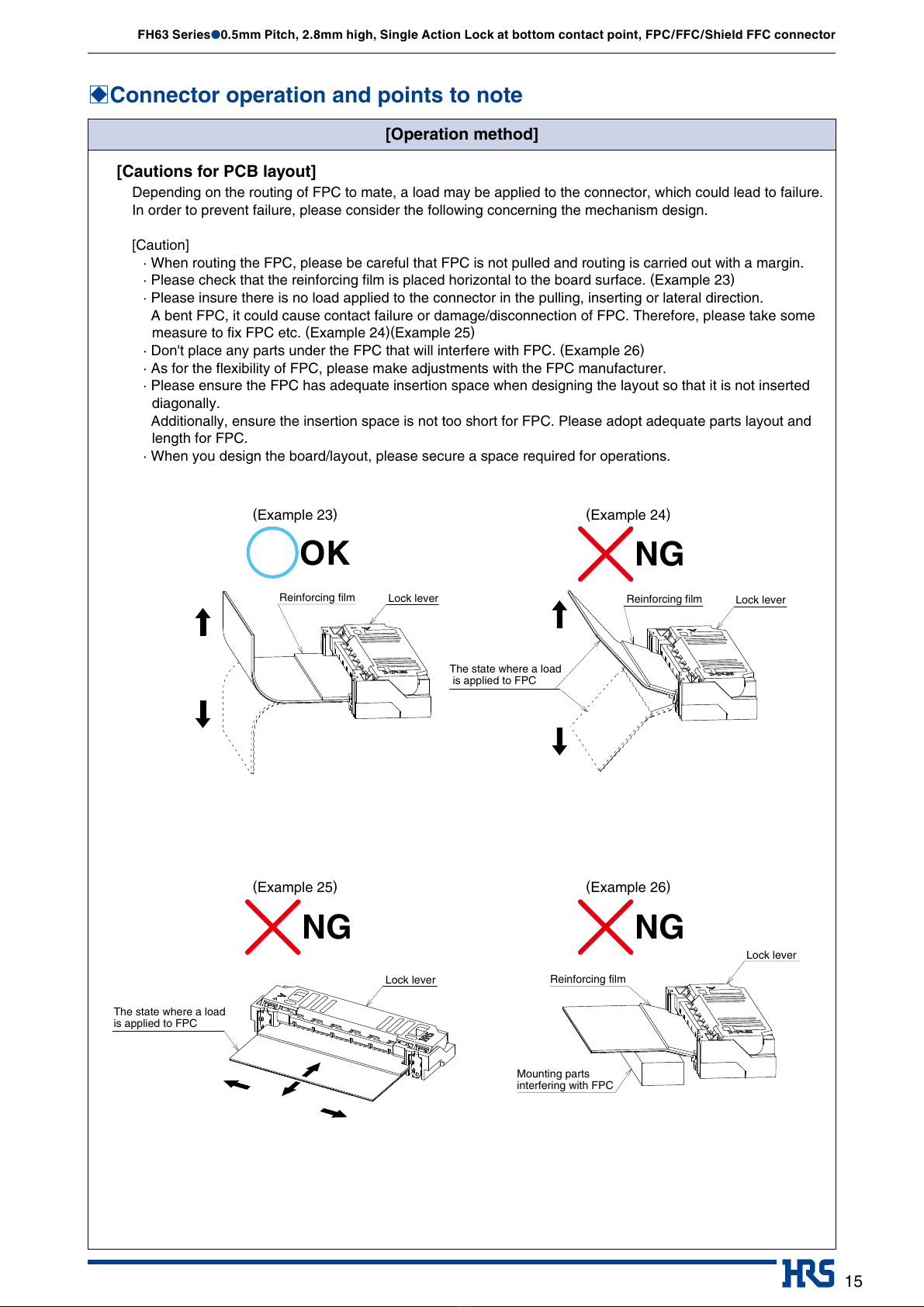
[Cautions for PCB layout]
Depending on the routing of FPC to mate, a load may be applied to the connector, which could lead to failure.
In order to prevent failure, please consider the following concerning the mechanism design.
[Caution]
· When routing the FPC, please be careful that FPC is not pulled and routing is carried out with a margin.
· Please check that the reinforcing film is placed horizontal to the board surface. (Example 23)
· Please insure there is no load applied to the connector in the pulling, inserting or lateral direction.
A bent FPC, it could cause contact failure or damage/disconnection of FPC. Therefore, please take some
measure to fix FPC etc. (Example 24)(Example 25)
· Don't place any parts under the FPC that will interfere with FPC. (Example 26)
· As for the flexibility of FPC, please make adjustments with the FPC manufacturer.
· Please ensure the FPC has adequate insertion space when designing the layout so that it is not inserted
diagonally.
Additionally, ensure the insertion space is not too short for FPC. Please adopt adequate parts layout and
length for FPC.
· When you design the board/layout, please secure a space required for operations.
Lock lever Lock lever
Reinforcing film
Reinforcing film
Reinforcing film
Lock lever
Lock lever
The state where a load
is applied to FPC
The state where a load
is applied to FPC
Mounting parts
interfering with FPC
NGNG
OK NG
(Example 25) (Example 26)
(Example 23) (Example 24)
Mar.1.2018 Copyright 2018 HIROSE ELECTRIC CO., LTD. All Rights Reserved.

16
FH63 Series●0.5mm Pitch, 2.8mm high, Single Action Lock at bottom contact point, FPC/FFC/Shield FFC connector
The characteristics and the specifications contained herein are for reference purpose. Please refer to the latest customer drawings prior to use.
The contents of this catalog are current as of date of 08/2017. Contents are subject to change without notice for the purpose of improvements.
2-6-3,Nakagawa Chuoh,Tsuzuki-Ku,Yokohama-Shi 224-8540,JAPAN
TEL: +81-45-620-3526 Fax: +81-45-591-3726
http://www.hirose.com
http://www.hirose-connectors.com
®
BConnector operation and points to note
[Notes for mounting on the board/after mounting on the board]
[Notes for mounting on the board]
Please be careful of the following at the time of board mounting.
[Caution]
· Please confirm recommendations for mount board land shape, metal mask opening shape, and FPC
shape.
· If the land is narrower than recommend, or if the metal mask opening is wider than recommend, solder
(flux) wicking is more likely to occur.
If there is difference from the recommendation, please use check the mounted state.
· The level difference between the bottom surfaces of contact lead and the mold is designed to be small.
When there is silk print etc. on the bottom surface of the connector, it could push up the connector bottom
surface, and cause non-sticking solder or defective fillet formation.
When there is silk print etc. on the bottom surface of the connector, please use it after checking the
mounted state.
· Use the reflow conditions within the specifications of our company.
The mounted status may vary due to external conditions such as the type of cream solder, manufacturer,
and board size. Please use it after checking the mounted state.
· Please control the board warpage as much as possible. While the coplanarity of this connector is 0.1mm or
less, defective soldering could occur if the board warpage is considerable.
· When mounted on FPC, be sure to provide a reinforcing plate to ease handling. We recommend a
reinforcing plate of 0.3mm or thicker made of glass epoxy material.
· When pulling out the emboss from the reel, or when the connector is absorbed from the emboss and so on,
do not apply any excessive external force (of 1N or more) to the connector before mounting.
[Cautions when handling the board after mounting]
Please be careful of the following when handling the board after mounting operation.
[Caution]
· Do not apply any load to the board in the assembly process, such as "dividing a multi-piece board" or
"securing the board to the frame".
Such action could apply a load to the connector and damage it.
· Use the board with the deflection being 1mm or less when the board width is 100mm. (Example 27)
If the board has some deflection, it could apply a load to the connector and damage it.
[Cautions for hand-soldering]
Please be careful of the following when hand-soldering for repair work etc.
[Caution]
· Do not hand-solder while FPC is inserted.
· Please be careful not to apply excessive heat, or allow the solder iron to touch any place other than the
connector contact lead.
Such action could cause the connector to be deformed or melted.
· Do not supply an excessive amount of solder (flux).
If too much solder (flux) is supplied to the contact, the solder or flux could adhere on the contact point and
cause contact failure.
Additionally, if you supply too much solder to the reinforcing metal tabs the rotational action of the lock
lever could be defective and the connector could be damaged.
Connector
PCB
Connector
100
100
1 MAX1 MAX
(Example 27)
Mar.1.2018 Copyright 2018 HIROSE ELECTRIC CO., LTD. All Rights Reserved.
Powered by TCPDF (www.tcpdf.org)
This manual suits for next models
6
Table of contents
Other Hirose Cables And Connectors manuals

Hirose
Hirose GT16GM Series User manual

Hirose
Hirose BM10 Series User manual

Hirose
Hirose GT43 User manual

Hirose
Hirose DF62W Series Manual

Hirose
Hirose EnerBee DF60 Series User manual

Hirose
Hirose HIF Series User manual

Hirose
Hirose EnerBee DF60 Series User manual
 User manual")
Hirose
Hirose DF62WZ-6P-2.2DSA(20) User manual

Hirose
Hirose BM56G Series Instruction Manual

Hirose
Hirose GT50 Series User manual


