Hirose GT16GM Series User manual

GT16GM SERIES
IN-LINE WIRE HARNESS
INSTRUCTION MANUAL
COUNT
DESCRIPTION OF REVISIONS
DESIGNED
CHECKED
DATE
1
2
DIS-T-00002589
AM.YAMAUCHI
KT.MAKI
17.10.25
TITLE
GT16GM SERIES IN-LINE WIRE HARNESS INSTRUCTION MANUAL
APPROVED
KI.HIROKAWA
17.05.24
CHECKED
MO.OKADA
17.05.24
DESIGNED
MING.JIANG
17.05.23
WRITTEN
MING.JIANG
17.05.23
TECHNICAL SPECIFICATION
ETAD-T0652-00
1
1/ 6
FORM HC0011-9-1
HIROSE ELECTRIC CO.,LTD.
△
△
Jul.1.2022Copyright2022HIROSEELECTRICCO.,LTD.AllRightsReserved.

HIROSE ELECTRIC CO.,LTD.
ETAD-T0652-00
1
2/6
FORM HC0011-9-2
△
0
1. Parts Configuration
(1) Center contact
Model
HRS No.
GT16G-2428PCF
CL766-0046-0
(2) Insulator
Model
HRS No.
GT16G-PC
CL766-0047-3
(3) Outer contact
Model
HRS No.
GT16G-/1.6-2.9PC
CL766-0048-6
(4) Outer ferrule
Model
HRS No.
GT16G-1.5DHQS(L)
CL766-0111-0
(5) Contact ferrule
Model
HRS No.
GT16G-FR
CL766-0028-9
(6) Housing
Model
HRS No.
GT16GM-1P-HU
CL766-0050-8
GT16GMN-1PP-HU
CL766-0051-0
Jul.1.2022Copyright2022HIROSEELECTRICCO.,LTD.AllRightsReserved.

HIROSE ELECTRIC CO.,LTD.
ETAD-T0652-00
1
3/6
FORM HC0011-9-2
△
0
2. Applicable Cable
□1.5D-2W or equivalent
Note: The crimp condition varies with the structure of the cable. Check the cable before use.
3. Harness method
(1) Strip the cable sheath.
Note: 1. Refer to “The Crimp Quality Standard Sheet”for the cable-end processing dimensions.
2. Neatly cut the cable end before processing so that the core conductor, dielectric material,
outer conductor, and sheath will be aligned together.(Make sure that the cable is not
deformed.)
3. Pay utmost attention not to damage the cut edge of the core conductor, dielectric material,
or outer conductor.
(2) Use the dedicated jig and crimp the center contact.
Note: 1. Refer to “The Crimp Condition Table”for the crimp height.
Note: 2. Refer to “The Crimp Quality Standard Sheet”for the crimp work standards.
(3) Put the cable into the outer contact.
Note: 1. Check that the direction of the outer contact is correct as shown in the illustration below.
Note: 2. Pay attention not to deform the crimped contact.
Jul.1.2022Copyright2022HIROSEELECTRICCO.,LTD.AllRightsReserved.
HIROSE ELECTRIC CO.,LTD.
ETAD-T0652-00
1
4/6
FORM HC0011-9-2
△
0
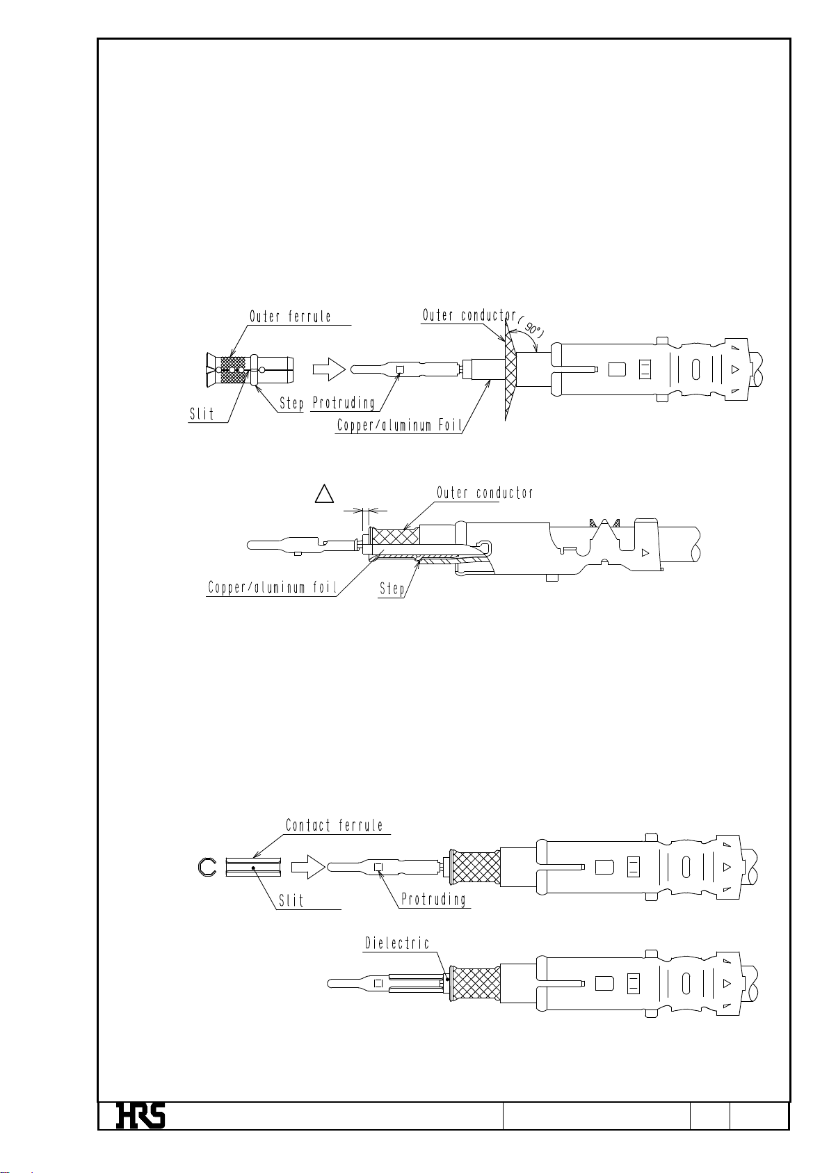
(4) Spread out the outer conductor with the dedicated tool, insert the outer ferrule, and return the outer
conductor to cover the outer ferrule.
Note: 1. Be careful not to unweave the outer conductor when spreading out the outer conductor.
Do not spread out the copper foil or aluminum foil. Make sure that the copper
foil and aluminum foil are inside the outer ferrule.
Note: 2. Check that the direction of the outer ferrule is correct as shown in the illustration below.
Coincide the slit of the outer ferrule with the protruding part of the center contact and
insert the outer ferrule.
Note: 3. Insert the outer ferrule until the step of the outer ferrule comes to the edge of the sheath.
Note: 4. Pay attention not to pull the outer conductor into the sheath when inserting the outer
ferrule.
(5) Use the dedicated jig and insert the contact ferrule from the mating side of the center contact until the
contact ferrule comes in contact with the dielectric material.
Note: 1. Check that the direction of the contact ferrule is correct as shown in the illustration below.
Coincide the slit of contact ferrule with the protruding part of the center contact and insert
the contact ferrule.
Note: 2. Pay attention not to deform the crimped contact.
0.2±
0.2
1
Jul.1.2022Copyright2022HIROSEELECTRICCO.,LTD.AllRightsReserved.

HIROSE ELECTRIC CO.,LTD.
ETAD-T0652-00
1
5/6
FORM HC0011-9-2
△
0
(6) Put the above contact unit onto the insulator, and fit another insulator onto the contact unit.
Note: 1. Put the protruding part of the center contact onto the groove hole.
Note: 2. Pull the cable at a force of approximately 4.9N and check that the contact unit will not be
pulled out.
(7) Assemble the outer contact to the insulator.
Note: 1. Check that the direction of the outer contact is correct as shown in the illustration below.
Make sure that the left and right dents on the insulator coincide with the grooves of the
outer contact in coaxial direction (i.e., the slit of the outer ferrule coincide in position with
the barrel bottom of the outer contact).
Note: 2. Insert the cable until the insulator is stopped by the groove end face of the outer contact.
Jul.1.2022Copyright2022HIROSEELECTRICCO.,LTD.AllRightsReserved.

HIROSE ELECTRIC CO.,LTD.
ETAD-T0652-00
1
6/6
FORM HC0011-9-2
△
0
1
(8) Use the dedicated jig and crimp the outer contact.
Note: 1. Refer to “The Crimp Condition Table”for the crimp height.
Note: 2. Refer to “The Crimp Quality Standard Sheet”for the crimp work standards.
Note: 3. Confirm that the insulator is fixed by the lance of the outer contact.
(9) Insert the outer contact into the housing.
Note: 1. Coincide the protruding part of the outer contact with the groove of the housing and insert
the outer contact.
Note: 2. Insert the outer contact until the position of the outer contact is fixed by the lance of the
housing.
(10) Harness work completed
0.4
Jul.1.2022Copyright2022HIROSEELECTRICCO.,LTD.AllRightsReserved.
Other Hirose Cables And Connectors manuals
 User manual")
Hirose
Hirose DF62WZ-6P-2.2DSA(20) User manual

Hirose
Hirose FH63 Series Manual

Hirose
Hirose HIF Series User manual

Hirose
Hirose DF62W Series Manual

Hirose
Hirose BM56G Series Instruction Manual

Hirose
Hirose GT50 Series User manual

Hirose
Hirose GT43 User manual

Hirose
Hirose EnerBee DF60 Series User manual

Hirose
Hirose BM10 Series User manual

Hirose
Hirose GT16G-1S-HU User manual


Popular Cables And Connectors manuals by other brands


LEGRAND
LEGRAND WIREMOLD MDSF installation instructions

Kenwood
Kenwood CA-U1EX instruction manual

Festo
Festo CPV10-VI-P Series Assembly instructions

Actisense
Actisense PRO-BUF-2 quick start guide

Gefen
Gefen EXT-HDMI-CAT5-145 user manual

Hall Research Technologies
Hall Research Technologies UHBX-3S user manual