12
11
14
70
115
5
15
88
210
96
500
No. Item Qty
Flare Insulator
1
Binder
2
Screw for Overturn
Prevention
(4.1 × 32)
8
Remote Controller
Holder
1
5
Screw for holder of
Remote Controller
(3.1 × 16)
2
6
AAA size Battery
2
7
Remote Controller
1
8
Insulator
(t3 × 160 × 600)
1
9
Screw for Overturn
Prevention
(4.0 × 34)
2
10
Insulator
(20 × 30 × 300)
1
11
Bush
3
12
Sheet
3
13
Air Purifying Filter
2
14
Hanger
1
CAUTION
CAUTION
CAUTION
WARNING
WARNING
CAUTION
INSTALLATION
MANUAL
SPLIT UNIT AIR CONDITIONER
INDOOR UNIT
RAF-XJ25QHAE
RAF-XJ35QHAE
RAF-XJ50QHAE
EN INSTRUCTION MANUAL
FOR SERVICE
PERSONNEL ONLY
●Carefullyreadthroughtheprocedures
ofproperinstallationbeforestarting
installation work.
●Thesalesagentshouldinform
customers regarding the correct
operationofinstallation.
●Explanationforoutdoorunitisinthe
“How To Use”(Instruction Manual) that
packedwithoutdoorunit.
Tools Needed For Installation Work
(Mark isexclusiveusetoolforR410A,R32)
● Screwdriver●MeasuringTape●Knife
●Saw●ø65mmPowerDrill●Hexagonal
WrenchKey( 4mm)●Wrench
(14,17,22,26,27mm) GasleakageDetector
●PipeCutter●Putty●VinylTape●Pliers
●FlareTool VacuumPumpAdapter
ManifoldValve Charge Hose Vacuum
Pump
Besurethattheunitoperatesinproperconditionafterinstallation.Explaintocustomertheproper
operationandmaintenanceoftheunitasdescribedintheuser’sguide.Askacustomertokeepthis
installation manual together with the instruction manual.
WARNING .......... Incorrect methods of installation may cause death or serious injury.
CAUTION .......... Improper installation may result in serious consequence.
Make sure to connect earth line.
This sign in the gures indicates prohibition.
SAFETY PRECAUTION
● Readthesafetyprecautionscarefullybeforeoperatingtheunit.
● Thecontentsofthissectionarevitaltoensuresafety.Pleasepayspecialattentiontothefollowingsign.
Access the full version of the
User Installation Manual by
scanning the code.
• Acircuitbreakermustbeinstalledinthehousedistributionboxforthedirectconnectedpower
supplycablestotheoutdoorunit.Incaseofotherinstallationsamainswitchwithacontactgapof
morethan3mmhastobeinstalled.Withoutacircuitbreaker,thedangerofelectricshockexists.
• Donotinstalltheunitnearalocationwherethereisammablegas.Theoutdoorunit
maycatchreifammablegasleaksaroundit.
• Pleaseensuresmoothowofwaterwheninstallingthedrainhose.Improperinstallingmaywet
your funiture.
• AnIECapprovedpowercordshouldbeused.Powercordtype:NYM.
•Theunitshouldbemountedatstable,non-vibratorylocationwhichcanprovidefull
supporttotheunit.
•Theelectriccablesshouldneitherbereworkednoradded.Makesuretousean
exclusivecircuitbreaker.Otherwisereorelectricshockmightoccurbyconnection
failure,isolationfailureorovercurrent.
•Makesuretoconnectcablestoterminalproperlyandterminalcovershouldclosermly.
Otherwise,overheatingatterminalcontact,reorelectricshockmightoccur.
•Makesurethatthereisnodustonanyconnectedpointsofelectriccablesandxrmly.
Otherwise,reorelectricshockmightoccur.
•Nonearbyheatsourceandnoobstructionneartheairoutletisallowed.
•Theclearancedistancesfromtop,rightandleftarespeciedingurebelow.
•Thelocationmustbeconvenientforwaterdrainageandpipeconnectionwiththe
outdoor unit.
•Toavoidinterferencefromnoise,pleaseplacetheunitanditsremotecontrolleratleast
1m from the radio and television.
•Toavoidanyerrorinsignaltransmissionfromtheremotecontroller,pleaseputthe
controllerfarawayfromhigh-frequencymachinesandhigh-powerwirelesssystems.
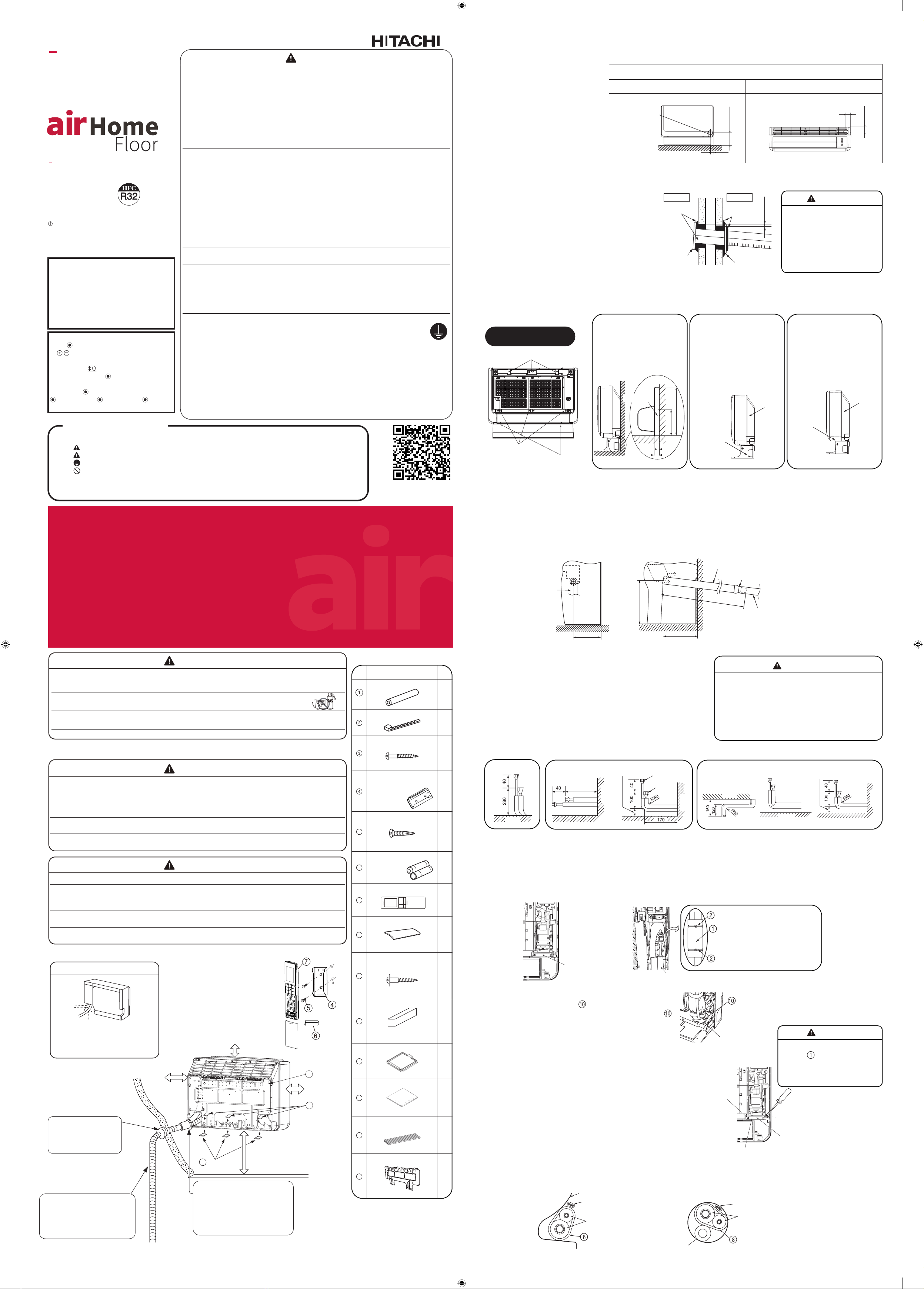
THE CHOICE OF MOUNTING SITE
(Pleasenotethefollowingmattersandobtainpermissionfromcustomerbeforeinstallation.)
[Indoor unit installation]
Piping conguration may be in three
different directions: direct rear piping,
right downward piping and right
sideways piping.
Drainpipe
Mustbeinstalled
separately.Insulateindoor
partofpipetoprevent
condensation.
Theindoorpipingshould
beinsulatedwiththe
enclosedinsulationpipe.(If
theinsulatorisinsucient,
pleaseusecommercial
products.)
Be sure to
completelyseal
anygapwithputty.
DirectionofPiping
(Forexample:Wallinstallation)
Above150mm
Above100mm
Sheet
Bush
When mounting on a wall
(upto150~500mmfromtheoorsurface)
Above200mm
Plug
WARNING
1. Installation of wall penetration and installation of protection pipe
2. Installation of the indoor unit
1.1 Hole position
2.1 How to remove the front cover
2.2 Drain pipe
2.3 Connecting the pipe to indoor unit
If there is a baseboard For sideways piping For oor piping
1.2 Wall penetration and installation of protection pipe
●
Pleaserequestyoursalesagentorqualiedtechniciantoinstallyourunit.Waterleakage,
shortcircuitorremayoccurifyoudotheinstallationworkyourself.
●
Pleaseobservetheinstallationstatedintheinstallationmanualduringtheprocessof
installation.Improperinstallationmaycausewaterleakage,electricshockandre.
●
Makesurethattheunitsaremountedatlocationswhichareabletoprovidefullsupportto
theweightoftheunits.Ifnot,theunitsmaycollapseandimposedanger.
●
Observetherulesandregulationsoftheelectricalinstallationandthemethodsdescribed
intheinstallationmanualwhendealingwiththeelectricalwork.Usecableswhichare
approvedocialinyourcountry.Besuretousethespeciedcircuit.Ashortcircuitand
remayoccurduetotheuseoflowqualitywireorimproperwork.
●
Besuretousethespeciedcablesforconnectingtheindoorandoutdoorunits.Please
ensure that the connections are tight after the conductors of the wire are inserted into the
terminalstopreventtheexternalforceisbeingappliedtotheconnectionsectionofthe
terminalbase.Improperinsertionandloosecontactmaycauseover-heatingandre.
●
Pleaseusethespeciedcomponentsforinstallationwork.Otherwise,theunitmay
collapseorwaterleakage,electricshock,reorstrongervibrationmayoccur.
●
BesuretousethespeciedpipingsetforR410A,R32.Otherwise,thismayresultin
brokencopperpipesorfaults.
●
Wheninstallingortransferringanairconditionertoanotherlocation,makesurethat
airotherthanthespeciedrefrigerant(R410A,R32)doesnotentertherefrigeration
cycle.Ifotherairshouldenter,thepressureleveloftherefrigerationcyclemayincrease
abnormallywhichcouldresultinaruptureandinjury.
●
Be sure to ventilate fully if a refrigerant gas leak while at work. If the refrigerant gas
comesintocontactwithre,apoisonousgasmayoccur.
●
Aftercompletionofinstallationwork,checktomakesurethatthereisnorefrigerationgas
leakage.Iftherefrigerantgasleaksintotheroom,comingintocontactwithreinthefan-
drivenheater,spaceheater,etc.,apoisonousgasmayoccur.
●
Unauthorizedmodicationstotheairconditionermaybedangerous.Ifabreakdown
occurspleasecallaqualiedairconditionertechnicianorelectrician.Improperrepairs
mayresultinwaterleakage,electricshockandre,etc.
●
Besuretoconnecttheearthlinefromthepowersupplywiretotheoutdoorunitand
betweentheoutdoorandindoorunit.Donotconnecttheearthlinetothegas
tube,waterpipe,lightingrodortheearthlineofthetelephoneunit.
Improperearthingmaycauseelectricshocks.
●
Whennishingtherefrigerantcollection(pumpingdown),stopthecompressorandthen
removethecoolantpipe.
Ifyouremovetherefrigerantpipewhilethecompressorisoperatingandtheservicevalve
isreleased,airissuckedandapressureinthefreezingcyclesystemwillbuildupsteeply,
causinganexplosionorinjury.
●
Wheninstallingtheunit,besuretoinstalltherefrigerantpipebeforestartingthe
compressor.Iftherefrigerantpipeisnotinstalledandthecompressorisoperatedwiththe
servicevalvereleased,airissuckedandthepressureleveloftherefrigerationcyclemay
increaseabnormallywhichcouldresultinaruptureandinjury.
NamesofIndoorComponents
NamesofIndoorComponents
●
Make a hole on the wall such
thepositionasshownbelow,
inordertokeeptheowfor
condensed water smooth.
●
Drillaø65mmholeonwallwhichisslightlytilted
towardstheoutdoorside.Drillthewallatasmall
angle.
●
Cuttheprotectionpipeaccordingtothewall
thickness.
●
Emptygapinthesleeveofprotectionpipeshould
becompletelysealedwithputtytoavoiddripping
of rain water into the room.
●Makesuredrainpipeslopesdownwardsothatdrainowssmoothlywithoutbeingtrappedinthemiddle.
●Thedrainhose(connectingportouterdiameter:16mmor20mm,length:500mm)isincludedintheindoorunit.Prepare
adrainpipeasshowninthefollowinggure.
●Topreventcondensation,theindoordrainpipeshouldbecoveredwithheatinsulationmaterialwithathicknessofmore
than 10mm.
●Afterpipingiscompleted,checktomakesurethatdraindischargessmoothly.Sealthedrainpipetightlywithtapeto
keepdirtout.
●
Drawinthepipesthroughtheholeofthewallortheoortoindoor.
●
Arrangethepipeshownbelow.Inthecasethatlargepipeand
smallpipearrangetomakeinfrontandbehind.
●
Theindoorpipingshouldbeinsulatedwiththeenclosedinsulation
pipe.
●
Thepipeshouldrstbecutlongerthanthelengthshownbelow.
●
Theexcesssectionofthepipeshouldbecutoffduringpipe
connection.
●
Remove PIPE SUPPORT.
●
Insert the drain hose into the hole in the wall.
●
Windinginsulationpipefordrainhoseandtaping4or5placestox.
●
ConnectthepipetotheIndoorunit.
●
Aftercompletingthepipingconnection,covertheconnectorwiththeinsulator.
●
Connect the cord (follow instructions in the section “5. Connection of the connecting cord” on the reverse of this sheet).
●
SincethereissomespacebetweenPIPESUPPORTand
thepipe,axtheinsulator to the PIPE SUPPORT.
Asshowninthegureontheright,axtheinsulator
to the PIPE SUPPORT to sandwich it.
●
Afterconnectingthepipesandconnectingcord,besure
toscrewPIPESUPPORTtightlyandxthepipesand
connecting cord.
●
Position the easy-to-attach side of PIPE SUPPORT (after
aligningitwiththepipe)tofacethefrontandsecure
it with a screw. (Be sure to install PIPE SUPPORT to
preventrodentsfromenteringtheindoorunit.)
●
Topreventthepipeconnectorfromcontactingthefront
cover,pushtheconnectorasfarasitgoes.
●
Arrangetheconnectingcord,pipesanddrainhoseneatly
andstoretheminthebottomsectionoftherearsurface
of the indoor unit.
●In the case of make
aholeontheoor. ●In the case of make a hole on the wall. ●Sidewayspiping. (Unit:mm)
Floor
above270
Beforepiping. Afterpiping. Topview
PIPE SUPPORT
Front view Right side view
Smallpipe
Largepipe
Wall
Wall
180mm or less
150mm or less
Front view Right side view Makesurethedrainhoseslopesdownward.
Connecting section
Drainpipe(procurelocally)
Drainhose
(Unit:mm)
●
Ifthebaseboardis
5~15mminthickness
and 115mm or less in
height,cutthepipe
bushingtoconformto
thebaseboard.
●
For right sideways
piping,cutthestand’s
bushingwithaplastic
cutter or similar tool and
usealeforanattractive
nish.
●
Foroorpiping,cutthe
frontcoverbushingwith
aplasticcutterorsimilar
toolandusealeforan
attractivenish.
Please refer to section for details.
Screw(3pieces)
Screw(3pieces)
Screw(2pieces)
Baseboard
Bushing (2
piecesoneach
side)
Cabinet
Cabinet
Front cover
bushing
Seal with
putty
Protection
pipe
Sleeve of
protectionpipe
WALL
Seal with
putty
Be sure that the wire is not in
contact with any metal in the
wall.Pleaseusetheprotection
pipeaswirepassingthrough
thehollowpartofthewallso
astopreventthepossibilityof
damagedbymouse.
Whenmountingtheare
insulator ,makesurethereis
aspacebetweentheinsulator
andleftofresinpart.Otherwise,
maycausewaterdripping.
Forsidewayspiping,donotinstallthedrainhose
sideways. Connect the drain hose so that it comes
out directly.
Sidewaysinstallationofthedrainhosewillprevent
itfromslopingdownward,causingwaterleakage.
Toavoiddripping,makesuretopassthedrainhose
underthepipe.
Drainhose
make lower
than center of
the hole.
55mm
65mm
184mm or less
80~100mm
2~5mm
Hole Position
In the case of making a hole on the wall. Inthecaseofmakingaholeontheoor.
Indoor Outdoor
Removal and installation of
front cover
Wall
Wall
Pipe
Binder
Insulator
PIPE SUPPORT
Screws
PIPE SUPPORT
Hook the PIPE
SUPPORTtabin
the square hole.
Indoor unit rear surface
Connecting cord
Connecting cord
Pipe
Pipe
Insulator
Insulator
Drainhose
MountPIPESUPPORTsothatthecylindricalportionofthedrain
panpassesthroughitsholeandsecureitwithscrewslocatedat
therightbackcorner.
Pipe/drainhoselayoutwhenpassingthroughthe
wall hole
Pipelayoutoftheunitrearsurface
Binder
Flare
insulator
Wrapareinsulation,
bindtopandbottom
areinsulationby
binder.Wraptapeon
areinsulationclosely.
Floor
EE0019567D rev. 0-10/2023
Cooling & Heating


 User manual")


 null")


