manuals.online logo
Brands
  1. Home
  2. •
  3. Brands
  4. •
  5. Hitachi
  6. •
  7. Air Conditioner
  8. •
  9. Hitachi RAC-DJ50PCAT User manual

Hitachi RAC-DJ50PCAT User manual

SAFETY PRECAUTION
●Read the safety precautions carefully before operating the unit.
●The contents of this section are vital to ensure safety. Please pay special attention to the following sign.
WARNING ........ Incorrect methods of installation may cause death or serious injury.
CAUTION ......... Improper installation may result in serious consequence.
Be sure that the unit operates in proper condition after installation. Explain to customer the proper way of operating
the unit as described in the user’s guide.
< IA2270: A >
Tools Needed For Installation Work
!
!
WARNING
!
●Carefully read through the procedures of
proper installation before starting installation
work.
●The sales agent should inform customers
regarding the correct operation of installation.
(mark is tool exclusive use for R32)
●+–
Screwdriver
●
Measuring Tape
●
Knife
●
Saw
●
Pipe Cutter
●
Hexagonal Wrench Key ( 4mm)
●
Power Drill (ø 65mm ~ ø 80mm)
Vacuum Pump
●
Pliers or Wrench
●
Torque Wrench Vacuum Pump Adaptor
●
Flare Tool
●
Gas Leakage Detector
Manifold Valve Charge Hose
●
Reamer
●
File
INSTALLATION
MANUAL
SPLIT UNIT AIR CONDITIONER
OUTDOOR UNIT
RAC-DJ50PCAT
RAC-DJ60PCAT
RAC-DJ70PCAT
EN INSTRUCTION MANUAL
FOR SERVICE
PERSONNEL ONLY
<
IA2270: A >
Home
Refrigerant pipe size (outer diameter): Narrow pipe, Liquid (ø6.35mm); Wide pipe, Gas (ø12.70mm/ø15.88mm)
●Flare nut must use a torque wrench without fail. Tighten with the specified tightening torque.
If the flare nut is tightened too much, after a long period of time, the flare nut breaks, Gas
leakage, stagnation, touching fire, rarely cause ignition.
●Sharp bending of the pipe use the polyethylene rod, bend not crushed the pipe. Gas leakage
from the crushed part, stagnation, touching fire, rarely cause ignition.
●Please request your sales agent or qualified technician to install your unit. Water leakage,
short circuit or fire may occur if you do the installation work yourself.
●Please observe the instructions stated in the installation manual during the process of
installation. Improper installation may cause water leakage, electric shock and fire.
●A brazed, welded, or mechanical connection shall be made before opening the valves to
permit refrigerant to flow between the refrigerating system parts. A vacuum valve shall be
provided to evacuate the interconnecting pipe and/or any uncharged refrigerating system
part.
●Mechanical connectors used indoors shall comply with ISO 14903. When mechanical connectors
are reused indoors, sealing parts shall be renewed. When flared joints are reused indoors,
the flare part shall be re-fabricated.
●Refrigerant tubing shall be protected or enclosed to avoid damage.
●Make sure that the units are mounted at locations which are able to provide full support to
the weight of the units. If not, the units may collapse and impose danger.
●Observe the rules and regulations of the electrical installation and the methods described in
the installation manual when dealing with the electrical work. Use power cables approved
by the authorities of your country.
●Be sure to use the specified wire for connecting the indoor and outdoor units. Please ensure
that the connections are tight after the conductors of the wire are inserted into the terminals.
Improper insertion and loose contact may cause over-heating and fire.
●Please use the specified components for installation work. Otherwise, the units may collapse
or water leakage, electric shock and fire may occur.
●Be sure to use the specified piping set for R32. Otherwise, this may result in broken copper
pipes or faults.
●When installing or removing an air conditioner, only specified refrigerant (R32) shall be
allowed, do not allow air or moisture to remain in the refrigeration cycle. Otherwise, pressure
in the refrigeration cycle may become abnormally high so that a rupture may be caused.
●Be sure to ventilate fully if a refrigerant gas leak while at work. If the refrigerant gas comes
into contact with fire, a poisonous gas may occur. Be aware that refrigerants may not contain
an odour.
●After completion of installation work, check to make sure that there is no refrigeration gas
leakage. If the refrigerant gas leaks into the room, coming into contact with fire in the fan-
driven heater, space heater, etc., a poisonous gas may occur.
●Unauthorized modifications to the air conditioner may be dangerous. If a breakdown occurs
please call a qualified air conditioner technician or electrician. Improper repairs may result
in water leakage, electric shock and fire, etc.
WARNING
●The Outdoor unit must be mounted at a location which
can support heavy weight. Otherwise, noise and vibration
will increase.
CAUTION
!
●Do not expose the unit under direct sunshine or
rain. Besides, ventilation must be good and clear of
obstruction.
●The air blown out of the unit should not point directly
to animals or plants.
●The clearances of the unit from top, left, right and front
are specified in Figure 1. At least 3 of the above sides
must be open air.
●Be sure that the hot air blown out of the unit and noise
do not disturb the neighbourhood.
●Do not install at a location where there is flammable
gas, steam, oil and smoke.
●The location must be convenient for water drainage.
●Place the Outdoor unit and its connecting cord at least
1m away from the antenna or signal line of television,
radio or telephone. This is to avoid noise interference.
●Do not install outdoor unit facing strong wind direction.
It may damage the fan motor.
●Do not install the outdoor unit in a place where small
animals may build their nests. If small animal goes
inside the unit and touches the electrical parts, failure
of the unit, smoke or fire may be caused. Request your
customer to keep the surrounding of the unit is clean.
OUTDOOR UNIT
!
The Choice of Mounting Site (Please note the following matters and obtain permission from customer before installation).
Dimension of Mounting Stand of the Outdoor unit
(unit : mm)
mounting stand
CAUTION
!
●A circuit breaker or fuse must be installed. Without a circuit breaker or fuse the danger of electric shock exists.
The external switch shall be incorporated to completely disconnect from power supply. It should disconnect all
poles, and a contact separation of at least 3mm must be present.
●Do not install the unit near a location where there is flammable gas. The outdoor unit may catch
fire if flammable gas leaks around it.
●
Do not install the indoor unit in a machine shop or kitchen where vapor from oil or its mist flows to the indoor
unit. The oil will deposit on the heat exchanger, thereby reducing the indoor unit performance and may deform
and in the worst case, break the plastic parts of the indoor unit.
●Please ensure smooth flow of water when installing the drain hose.
●Piping shall be suitable supported with a maximum spacing of 1m between the supports.
●Do not use means to accelerate the defrosting process or to clean, other than those recommended by the
manufacturer. Any unfit method or using incompatible material may cause product damage, burst and serious
injury.
●The appliance/pipe-work shall be stored in a well ventilated room with indoor floor area larger than Amin [refer
to Table 1] and without any continuously operating ignition source. Keep away from open flames, any operating
gas appliances or any operating electric heater. Else, it may explode and cause injury or death.
●The appliance/pipe-work shall be installed, and/or operated in a room with floor area larger than Amin [refer to
Table 1] and keep away from ignition sources, such as heat/spark/open flame or hazardous areas such as gas
appliances, gas cooking, reticulated gas supply systems or electric cooking appliances, etc.
●Do not pierce or burn as the appliance/pipe-work is pressurized. Do not expose the appliance/pipe-work to heat,
flame, sparks, or other sources of ignition. Else, it may explode and cause injury or death.
WARNING
!
This symbol shows that this
equipment uses a flammable
refrigerant.
If the refrigerant is leaked,
together with an external
ignition source, there is a
possibility of ignition.
This symbol shows that the
Operation Instructions should
be read carefully.
This symbol shows that a
service personnel should be
handling this equipment with
reference to the Installation
Manual.
This symbol shows that there
is information included in
the Operation Manual and/or
Installation Manual
WARNING
CAUTION
CAUTION
CAUTION
!
BURST HAZARD
Do not allow air, etc. to get
into refrigerant cycle (piping)
RISK OF EXPLOSION
Compressor must be stopped
before removing refrigerant
pipes.
All service valve must be fully
closed after pumping down
operation.
WARNING
Table 1: Minimum Floor area of the room A
min
(m
2
)
Minimum Floor area of the room
A
min
(m
2
)
RAC-DJ**PCAT
Max refrigerant
charge amount
(g)
Max Piping
Length
(m)
Outdoor
Model
RAC-DJ50PCAT
RAC-DJ60PCAT
RAC-DJ70PCAT
30
30
30
1400
1400
1400
1.85
1.85
1.85
OUTDOOR UNIT
●Please mount the Outdoor unit on stable ground to prevent vibration and increase of noise level.
●Decide the location for piping after sorting out the different types of pipe available.
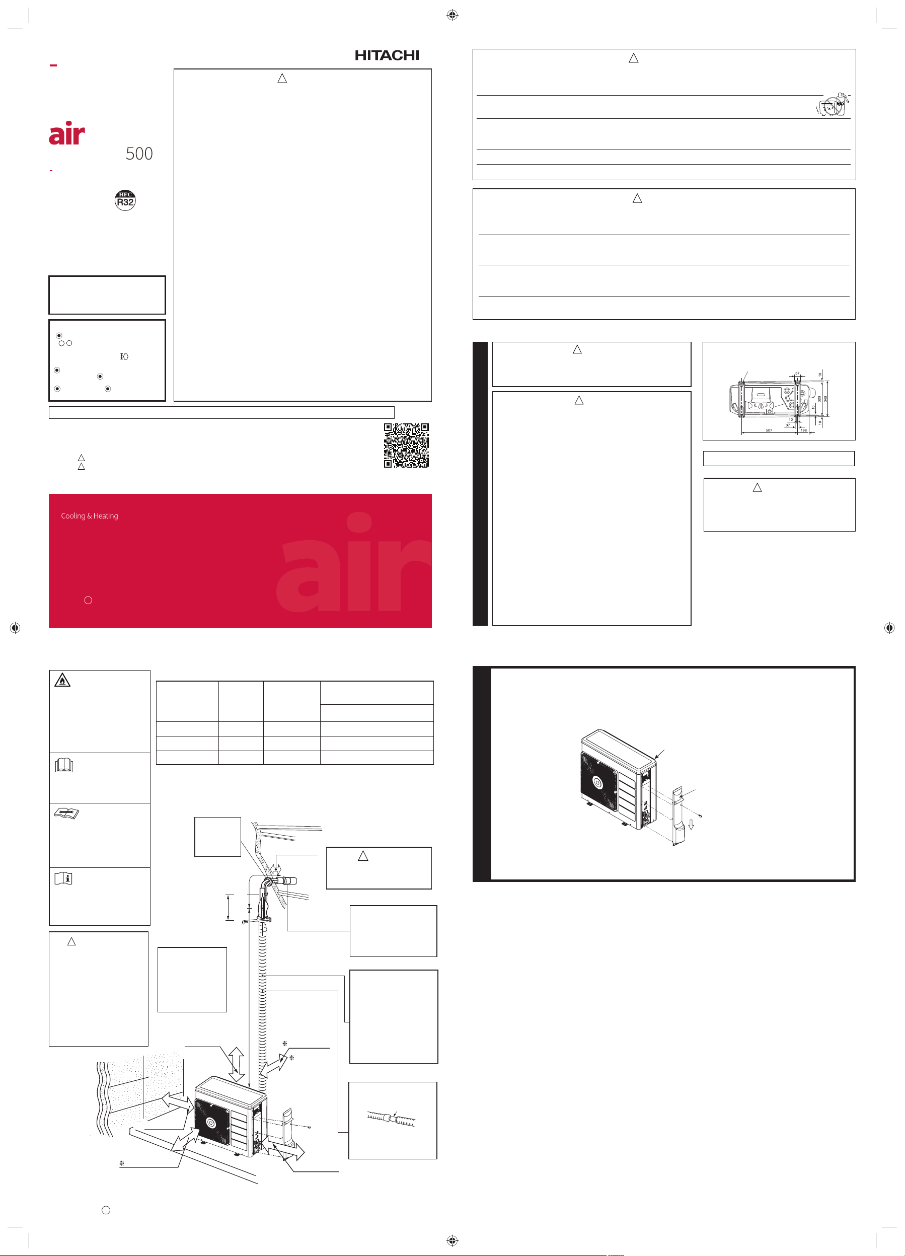
●When removing side cover, please pull the handle after undoing the hook by pulling it downward.



Please face this side (suction side)
of the unit to the wall.
Please remove side cover
when connecting the piping and
connecting cord.
Pull downward
●The difference in height
between the indoor and
outdoor unit should be
kept max 20m.
●The connecting pipe,
no matter big or small,
should all be insulated
with insulation pipe and
then wrapped with vinyl
tape. (The insulator will
deteriorate if it is not
wrapped with tape).
The connection of insulated
drain hose.
Please use insulated drain
hose for the indoor piping
(commercial product).
The indoor piping should
be insulated with the
enclosed insulation
pipe. (If the insulator is
insufficient, please use
commercial products).
Be sure to
completely
seal any gap
with putty. above 100mm
above 300mm
about
400mm
must not bend
Maximum pipe length 30m
Minimum pipe length 3m
above 200mm above 100mm
give
clearance
as wide as
possible
above 100mm
above 700mm above 200mm
Figure 1
inner diameter ø 16mm
Refrigerant piping
must be protected
from physical
damage. Install a
plastic cover or
equivalent.
Flare connection only at outside
of building
WARNING
!
Figure showing the Installation of Outdoor Unit.
●This unit is chargeless up 30m pipe length.
●Installation of pipe length less than minimum
pipe length requirement (3 meters) may
generate an abnormal sound.
CAUTION
!
Preparation of Pipe
1
●Use a pipe cutter to cut the copper pipe.
●Jagged edge will cause leakage.
●Point the side to be trimmed downwards during trimming to prevent copper chips from entering
the pipe.
●Before flaring, please put on the flare nut.
Pipe Connection
2
INSTALLATION OF REFRIGERATING PIPES AND AIR REMOVAL
CAUTION
!
●Recommend to use
R32 flaring tool.
CAUTION
!
In case of removing flare nut of an Indoor unit, first remove a nut of small diameter
side, or a seal cap of big diameter side will fly out. Prevent water from entering
into the piping when working.
Trimming tool
Copper pipe
Die
Die
Copper pipe
Flare nut
Torque
wrench
Wrench
Removal Of Air From The Pipe And Gas Leakage Inspection
Gas Leakage Inspection
Please use gas leakage
detector to check if leakage
occurs at the connection
of Flare nut as shown on
the right.
If gas leakage occurs, further
tighten the connection to
stop leakage. (Be sure to
use R32 detector)
3
AIR REMOVAL
When the meter reaches - 101KPa (-76cmHg) during
pumping, fully tighten the shuttle.
Closed R32
Valve
Charge hose
Vacuum
pump
adapter
When pumping starts, slightly loosen the flare nut to
check of air sucked in. Then tighten the flare nut.
Lo Hi
Vacuum pump
Manifold valve
Meter showing pressure
Valve
Procedures of using Vacuum Pump for Air Removal
As shown in right figure, remove the cap of valve core.
Then, connect the charge hose. Remove the cap of
valve head. Connect the vacuum pump adapter to the
vacuum pump and connect the charge hose to the
adapter.
Fully tighten the “Hi” knob of the manifold valve and
completely unscrew the “Lo” knob. Run the vacuum
pump for about 10~15 minutes, then completely tighten
the “Lo” knob and switch off the vacuum pump.
Completely unscrew the spindle of the service valve (at
2 places) in anti-clockwise direction to allow the flow of
refrigerant (using Hexagonal Wrench key).
Re-cap the service valve and tighten using wrench.
Check the cap’s periphery if there is any gas leakage.
The task is then completed.
Remove the charge hose and tighten the cap of valve
core. Check the cap’s periphery if there is any gas
leakage.
Cap of valve head
Cap of valve head
The body of service valve
Hexagonal
Wrench Key
Cap of valve
core
Outer
Diameter
mm (inch)
6.35 (1/4")
9.52 (3/8")
12.70 (1/2")
15.88 (5/8")
1.0 ~ 1.5
1.0 ~ 1.5
1.0 ~ 1.5
1.0 ~ 1.5
Clutch type
A (mm)
1.5 ~ 2.0
1.5 ~ 2.0
1.5 ~ 2.5
1.5 ~ 2.5
Wing nut type
Thickness
(mm)
0.8
0.8
0.8
1.0
0.0 ~ 0.5
0.0 ~ 0.5
0.0 ~ 0.5
0.0 ~ 0.5
Flare tool for R32
Clutch type
Conventional flare tool
Outer
dia.of pipe
6.35 (1/4")
9.52 (3/8")
12.70 (1/2")
15.88 (5/8")
6.35 (1/4")
9.52 (3/8")
12.7 (1/2")
15.88 (5/8")
Valve
head cap
Torque N·m
(kgf ·cm)
14.0 – 18.0 (140 ~ 180)
33.0 – 42.0 (330 ~ 420)
50.0 – 62.0 (500 ~ 620)
63.0 – 77.0 (630 ~ 770)
19.6 – 24.5 (200 ~ 250)
19.6 – 24.5 (200 ~ 250)
29.4 – 34.3 (300 ~ 350)
29.0 – 31.0 (296 ~ 316)
12.3 – 15.7 (125 ~ 160)
Small dia. side
Large dia. side
Valve core cap
Small dia. side
Large dia. side
●Prevent moisture from entering pipe connection.
●Refrigerating machine oil not be applied to the outside of the
flare.
When refrigerating machine oil is applied to the outside of the
flare, excessive tightening of the flare nut, cracking of the flare
nut, destruction of the flare and gas leakage may occur.
●When using the control valve, do not use deteriorated packing.
And, do not overtighten the steering wheel.
Gas leakage from the service valve part, stagnation, touching
fire, rarely cause ignition.
CAUTION
!
1
2
3
4
5
CONNECTION OF POWER CORD
Procedures of Wiring
Indoor Unit Outdoor Unit
Detail of Cutting the Connecting Cord
Connecting cord
Outdoor UnitIndoor Unit
Power line
Green + Yellow
(ground)
Green + Yellow
(ground)
Connecting cord Connecting cord
Strip wires
Strip wires
Green + Yellow
●The naked part of the wire core should be 10 mm and fix it to the terminal tightly. Then try
to pull the individual wire to check if the contact is tight. Improper insertion may burn the
terminal.
●Be sure to use only wire specified for the use of air-conditioner.
●Please refer to the manual for wire connection and the wiring technique should meet the
standard of the electrical installation.
●There is an AC voltage drop between the LN terminal if the power is on. Therefore, be sure
to remove the plug from its socket.
WARNING
!
WARNING
!
●Leave some space in the connecting cord for
maintenance purpose and be sure to secure it
with the cord band.
●Secure the connecting cord along the coated
part of the wire using the cord band. Do not
exert pressure on the wire as this may cause
overheating or fire.
Wiring of The Outdoor Unit
●Please remove the side plate for wire connection.
WARNING
!
●If you cannot attach the side plate due to the connection cord, please press the connecting cord in
the direction to the front panel to fix it.
●Be sure that the hooks of the side plate is fixed in certainly. Otherwise water leakage may occur
and this causes short circuit or faults.
●The connecting cord should not touch to service valve and pipes. (It becomes high temperature in
heating operation.)
●Before installation, the power source must be checked and necessary wiring work must be completed. To make
the wiring capacity proper, use the wire gauge list below for the wiring from house distribution fuse box to the
outdoor unit in consideration of the locked rotor current.
●Investigate the power supply capacity and other electrical conditions at the
installing location.
Depending on the model of room air conditioner to be installed, request the
customer to make arrangements for the necessary electrical work etc.
The electrical work includes the wiring work up the outdoor unit. In
localities where electrical conditions are poor, use of a voltage regulation
is recommended.
●Install outdoor for the room air conditioner within the reaching range of the
line cord.
Earth terminal
Outdoor supply cords shall not be lighter
than polychloroprene sheathed flexible
cord with code designation 60245 IEC 57.
Wire length
up to 30 m
Wire cross-section
1.5mm2
For (Connecting cord - 1, 2, 3, Earth)
Wire cross-section
2.5 mm2
For (Power cord - L, N, Earth)
!
WARNING THIS APPLIANCE MUST BE EARTHED.
Power cord
Checking for the electric source and the voltage range
Cover
CAUTION
FINAL STAGE OF INSTALLATION
Insulation And Maintenance Of Pipe Connection
●The connected terminals should be completely sealed with heat insulator
and then tied up with rubber strap.
●Please tie the pipe and power line together with vinyl tape as shown
in the figure showing the installation of Indoor and Outdoor units. Then
fix their position with holders.
●To enchance the heat insulation and to prevent water condensation,
please cover the outdoor part of the drain hose and pipe with insulation
pipe.
●Completely seal any gap with putty.
1
Insulation material for pipe connection
Putty
Putty
Sleeve of
protection pipe
< IA2270: A >
Power Source And Operation Test
2
Power Source
WARNING
●Never remodel the power plug nor extend the long-distance
cord.
●Keep additional length for the power cord and do not
render the plug under external force as this may cause
poor contact.
●Do not fix the power cord with U-shape nail.
●The power cable easily generates heat. Do not bring the
cable together with a wire or vinyl tie.
Operation Test
●Please be sure to measure the supply voltage before operation
test.
●Please ensure that the air conditioner is in normal operating
condition during the operation test.
1. Operate with Cool Mode(in summer) or Heat Mode(in
winter).
2. Press Temperature Button on the remote controller to set
the desired temperature to 16.0°C for Cool Mode or 32.0°C
for Heating Mode.
Set the desired fan speed to " "(High).
!
CAUTION
!
●Don't operate for over 5 minutes with
the situation that the spindle of the
service valve is closed. This will cause
the defect.
●Don't operate by Cool Mode or Dry
Mode with the door and windows
opened, (the room humidity is always
above 80%) for a long period of time.
Water will condense and drip down
occasionally. This will wet your furniture.
●Explain to your customer the proper
operation procedures as described in the
user' s manual.
●If the indoor unit won't operate, check the
cable for correct connection.
●Turn on the lamp in the room where the
indoor unit is installed and check the
remote controller for normal operation.
3. Operate the air conditioner for 20 minutes at
least and make sure that the air from the air
conditioner is cool or warm.
4. Press the ON/Off button on the remote
controller to make sure that the air conditioner
stops running.
●If the indication lamps of the indoor unit blink
with sounding the buzzar during the operation
test, perform a check following the procedures
below.
●Before the check and the reoperation, reset the
power supply by turning off and on the circuit
breaker only after
●waiting for at least 5 mintes; or
●pressing the Temporary Switch Button only once
while the power is OFF.
Indication lamps
blinking mode What do check
All indication
lamps blink three
times repeatedly.
Make sure that the spindles
of both service valves are
open. (Outdoor fan might
operate for near 15 minutes
after the operation stop
for the protection. For the
reoperation at that case, do
it after outdoor fan will stop.)
IMPORTANT
Circuit Breaker
20A

This manual suits for next models

3

Other Hitachi Air Conditioner manuals

Hitachi RAK-VJ25PHAT User manual

Hitachi

Hitachi RAK-VJ25PHAT User manual

Hitachi Summit RAS-70YH5 User manual

Hitachi

Hitachi Summit RAS-70YH5 User manual

Hitachi RAC-S10CDT User manual

Hitachi

Hitachi RAC-S10CDT User manual

Hitachi RAS-260GA User manual

Hitachi

Hitachi RAS-260GA User manual

Hitachi RAF-25NXA1 User manual

Hitachi

Hitachi RAF-25NXA1 User manual

Hitachi RAK-60NH4 User manual

Hitachi

Hitachi RAK-60NH4 User manual

Hitachi RAS-30MH1 User manual

Hitachi

Hitachi RAS-30MH1 User manual

Hitachi RAK-18NH6AS User manual

Hitachi

Hitachi RAK-18NH6AS User manual

Hitachi Set Free mini-HNRQ1 Series User manual

Hitachi

Hitachi Set Free mini-HNRQ1 Series User manual

Hitachi P-AP160NA1 User manual

Hitachi

Hitachi P-AP160NA1 User manual

Hitachi RAS-08PH1 User manual

Hitachi

Hitachi RAS-08PH1 User manual

Hitachi RAS-S24H2AA User manual

Hitachi

Hitachi RAS-S24H2AA User manual

Hitachi RAC-60YH7 User manual

Hitachi

Hitachi RAC-60YH7 User manual

Hitachi RAS-25YHA User manual

Hitachi

Hitachi RAS-25YHA User manual

Hitachi YUTAKI Series User manual

Hitachi

Hitachi YUTAKI Series User manual

Hitachi air Core 700 Instruction Manual

Hitachi

Hitachi air Core 700 Instruction Manual

Hitachi RAS-S33H2A User manual

Hitachi

Hitachi RAS-S33H2A User manual

Hitachi RPI-30MH1 User manual

Hitachi

Hitachi RPI-30MH1 User manual

Hitachi Summit RAC-60YH5 User manual

Hitachi

Hitachi Summit RAC-60YH5 User manual

Hitachi RAS-E24CAK User manual

Hitachi

Hitachi RAS-E24CAK User manual

Hitachi RAS-X10CCK User manual

Hitachi

Hitachi RAS-X10CCK User manual

Hitachi airHome 300 CJ Series User manual

Hitachi

Hitachi airHome 300 CJ Series User manual

Hitachi RAK-65NH5 User manual

Hitachi

Hitachi RAK-65NH5 User manual

Hitachi RAS-DX10CSK User manual

Hitachi

Hitachi RAS-DX10CSK User manual

Popular Air Conditioner manuals by other brands

Pioneer FAB Series installation manual

Pioneer

Pioneer FAB Series installation manual

Panasonic CS-E15NKE3 operating instructions

Panasonic

Panasonic CS-E15NKE3 operating instructions

Daikin FTKS50EV1B Operation manual

Daikin

Daikin FTKS50EV1B Operation manual

GOETTL GH UNITS User's information manual

GOETTL

GOETTL GH UNITS User's information manual

Sanyo CH0971 Technical & service manual

Sanyo

Sanyo CH0971 Technical & service manual

Argo Relax Service manual

Argo

Argo Relax Service manual

York YNKFZC024-055BAADAFX owner's manual

York

York YNKFZC024-055BAADAFX owner's manual

Mitsubishi Electric PLA-SP BA Series Operation manual

Mitsubishi Electric

Mitsubishi Electric PLA-SP BA Series Operation manual

Tycoon TS2MVI32-09 Service manual

Tycoon

Tycoon TS2MVI32-09 Service manual

Diplomat DX-80CHRC instruction manual

Diplomat

Diplomat DX-80CHRC instruction manual

Mitsubishi Electric MSZ-FA25VA Service manual

Mitsubishi Electric

Mitsubishi Electric MSZ-FA25VA Service manual

Sharp AU-1802Y Operation manual

Sharp

Sharp AU-1802Y Operation manual

Daikin Comfort Flex CLIV Series Installation, operation and maintenance manual

Daikin

Daikin Comfort Flex CLIV Series Installation, operation and maintenance manual

LG LSN-HSV2 owner's manual

LG

LG LSN-HSV2 owner's manual

Frigidaire GHWQ103WC1 use & care

Frigidaire

Frigidaire GHWQ103WC1 use & care

LG PM12SP NSJ owner's manual

LG

LG PM12SP NSJ owner's manual

Toshiba HWS-455XWHM3-E owner's manual

Toshiba

Toshiba HWS-455XWHM3-E owner's manual

Lennox LIFHC012021T431E-1 owner's manual

Lennox

Lennox LIFHC012021T431E-1 owner's manual

manuals.online logo
manuals.online logoBrands
  • About & Mission
  • Contact us
  • Privacy Policy
  • Terms and Conditions

Copyright 2025 Manuals.Online. All Rights Reserved.