manuals.online logo
Brands
  1. Home
  2. •
  3. Brands
  4. •
  5. Hitachi
  6. •
  7. Air Conditioner
  8. •
  9. Hitachi RAF25NH4 User manual

Hitachi RAF25NH4 User manual

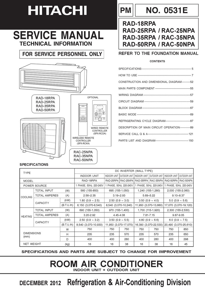
SM0757
RAM70QH4
(MULTIZONE 70H)
RAM80QH4
(MULTIZONE 80H)
RAF25NH4
RAF50NH4
RAD25QH4
RAD40QH4
SERVICE MANUAL
TECHNICAL INFORMATION
INFORMATIONS TECHNIQUES
REFER TO THE FOUNDATION MANUAL
REPORTEZ-VOUS AU MANUEL DE BASE
SPECIFICATIONS AND PARTS ARE SUBJECT TO CHANGE FOR IMPROVEMENT
LES SPECIFICATIONS ET PIECES DETACHEES PEUVENT CHANGER POUR ETRE AMELIOREES.
FOR SERVICE PERSONNEL ONLY
RESERVE AU PERSONNEL
SPECIFICATIONS
CARACTERISTIQUES GENERALES
SPECIFICATIONS 8
CARACTERISTIQUES GENERALES
FEATURES 28
CARACTÉRISTIQUES
HOW TO USE 44
UTILISATION
INSTALLATION 72
INSTALLATION
CONSTRUCTION AND DIMENSIONAL DIAGRAM 76
DIMENSIONS DES UNITÉS
MAIN PARTS COMPONENT 84
PRINCIPAUX COMPOSANTS
WIRING DIAGRAM 86
SCHÉMAS ÉLECTRIQUES
WIRING DIAGRAM OF THE PRINTED WIRING BOARD
93
SCHÉMA ÉLECTRIQUE DU CIRCUIT IMPRIMÉ
BLOCK DIAGRAM 111
ORGANIGRAMME DE CONTROLE
BASIC MODE 115
MODE DE BASE
REFRIGERATING CYCLE DIAGRAM 164
SCHÉMA DU CYCLE DE RÉFRIGÉRATION
DESCRIPTION OF MAIN CIRCUIT OPERATION
183
DESCRIPTION DES PRINCIPAUX CIRCUITS ÉLECTRIQUES
SERVICE CALL Q&A 236
MODE OPERATOIRE DE DEPANNAGE
DISASSEMBLY AND REASSEMBLY 244
DEMONTAGE ET REMONTAGE
TROUBLE SHOOTING 256
DETECTION DES PANNES
PARTS LIST AND DIAGRAM 302
LISTE DES PIÉCES DE RECHANGE ET DIAGRAMME
CONTENTS
TABLE DES MATIERES
TYPE TYPE
MODEL MODÈLE
POWER SOURCE PHASE/TENSION/FREQUENCE
TOTAL INPUT
PUISSANCE ABSORBEE TOTALE
(W)
TOTAL AMPERES
AMPERES TOTAUX (A)
CAPACITY
CAPACITE (kW)
(B.T.U./h)
TOTAL INPUT
PUISSANCE ABSORBEE TOTALE
(W)
TOTAL AMPERES
AMPERES TOTAUX (A)
CAPACITY
CAPACITE (kW)
(B.T.U./h)
W, L
DIMENSIONS DIMENSIONS (mm) H, H
D, P
NET WEIGHT POIDS NET (kg)
DC INVERTER TRIPLE AND QUADRUPLE SYSTEM MULTI
SYSTEME DE TRIPLE ET QUADRUPLE ONDULEUR CC MULTI
INDOOR UNIT UNITÉ INTÉRIEURE
OUTDOOR UNIT UNITÉ EXTÉRIEURE
750
600
215
15.0
750
235
400
14.0 77 79
1ø, 230V, 50Hz
RAF25NH4 RAF50NH4
REFER TO THE SPECIFICATIONS PAGE 10.
REPORTEZ-VOUS AUX SPECIFICATIONS DE LA PAGE 11.
ROOM AIR CONDITIONER
INDOOR UNIT + OUTDOOR UNIT
APRIL 2003 Hitachi Home & Life Solutions, Inc.
RAD25QH4
RAD40QH4
û
CH
RAF25NH4
RAF50NH4
RAM70QH4
RAM80QH4
COOLING
RÉFRIGÉRATION
HEATING
CHAUFFAGE
RAD25QH4 RAD40QH4
RAM70QH4 RAM80QH4
*After installation Après installation
850 (+90)*
830
340 (+50)*
1. In order to disassemble and repair the
unit in question, be sure to disconnect the
power cord plug from the power outlet
before starting the work.
2. If it is necessary to replace any parts, they should be replaced with respective genuine parts for the unit,
and the replacement must be effected in correct manner according to the instructions in the Service
Manual of the unit.
3. fter completion of repairs, the initial state should be
restored.
4. Lead wires should be connected and laid as in the
initial state.
5. Modification of the unit by the user himself should
absolutely be prohibited.
6. Tools and measuring instruments for use in repairs or inspection should be accurately calibrated in
advance.
7. In installing the unit having been repaired, be careful to prevent the occurrence of any accident such as
electrical shock, leak of current, or bodily injury due to the drop of any part.
8. To check the insulation of the unit, measure the insulation resistance between the power cord plug and
grounding terminal of the unit.
The insulation resistance should be 1M
Ω
or more as measured by a 500V DC megger.
9. The initial location of installation such as window, floor or the other should be checked for being safe
enough to support the repaired unit again.
If it is found not so strong and safe, the unit should be installed at the initial location after reinforced or
at a new location.
10. ny inflammable object must not be placed
about the location of installation.
11. Check the grounding to see whether it is
proper or not, and if it is found improper,
connect the grounding terminal to the earth.
Spray
gasoline
gasbombe
thinner
   
If the contacts of electrical
parts are defective, replace
the electrical parts without
trying to repair them
1
2
3
4
5
DANGER
Ð2Ð
      
 
The standards provide for items to be generally observed in carrying and handling semiconductors in
relative manufactures during maintenance and handling thereof. (They apply the same to handling of
abnormal goods such as rejected goods being returned.)
  
(1) Micro computer
(2) Integrated circuits (I.C.)
( ) Field effective transistor (F.E.T.)
(4) P.C. boards or the like to which the parts mentioned in (1) and (2) of this paragraph are equipped.
! "    #$ %& '&$(%&)
(1) Use a conductive container for carrying and storing of parts. (Even rejected goods should be handled in
the same way.)
(2) When any part is handled uncovered (in counting, packing and the like), the handling person must
always use himself as a body earth. (Make yourself a body earth by passing one M ohm earth
resistance through a ring or bracelet.)
( ) Be careful not to touch the parts with your clothing when you hold a part even if a body earth is
being taken.
(4) Be sure to place a part on a metal plate with grounding.
(5) Be careful not to fail to turn off power when you repair the printed circuit board. At the same time,
try to repair the printed circuit board on a grounded metal plate.
HITACHII
C401TH1 ,188 UV
%)  &$*%# &%&
A conductive polyvinyl bag
IC
IC
Conductive sponge
%)  $+ '
Body earth (Elimik conductive band)
Clip for connection with
a grounding wire
1M
Ω
Ð4Ð
(6) Use a three wire type soldering iron including a grounding wire.
    
Use a high insulation mode (100V, 10M
Ω
or higher) when ordinary iron is to be used.
( ) In checking circuits for maintenance, inspection, or some others, be careful not to have the test probes
of the measuring instrument shortcircuit a load circuit or the like.
Bare copper wire (for body earth) Metal plate (of Al. stainless steel, etc.)
Working table
Resistor 1M
Ω
(1/2W)
Earth wirte
Staple
     
soldering iron
Grounding wire
Screw stop at the screwed
part using a rag plate
Ð6Ð
1. In quiet operation or stopping the running, its heard slight flowing noise of
refrigerant in the refrigerating cycle occasionally, but this noise is not abnormal for
the operation.
2. When it thunders near by, it is recommend to stop the operation and to disconnect
the power cord plug from the power outlet for safety.
3. The room air conditioner dose not start automaticaly after reco ery of the electric
power failure for pre enting fuse blowing. Re-press START / STOP button after 3
minutes from when unit stopped.
4. If the room air conditioner is stopped by adjusting thermostat, or missoperation, and
re-start in a moment, there is occasion that the cooling and heating operation does
not start for 3 minutes, it is not abnormal and this is the result of the operation of
IC delay circuit. This IC delay circuit ensures that there is no danger of blowing
fuse or damaging parts e en if operation is restarted accidentally.
5. This room air conditioner should not be used at the cooling operation when the
outside temperature is below 10ûC (50ûF).
6. This room air conditioner (the re erse cycle) should not be used when the outside
temperature is below Ð15ûC (5ûF).
If the re erse cycle is used under this condition, the outside heat exchanger is
frosted and efficiency falls.
7. When the outside heat exchanger is frosted, the front is melted by operating the
hot gas system, it is not trouble that at this time fan stops and the apour may
rise from the outside heat exchanger.
CAUTION

SPECIFICATIONS

 
  
  

  
 
   
   
 
 
 


 

    
 


   
  !"
        
" 



EU1013DD×2
 
 
 !$%"
 &'

 
 
 
 '" 
  %!
  
 ( 
!    

※
) %'" *
+) %'" *
 & + &
  $
& && 
'%  
("' (" ' ("' (' ' (, ' ( '
※
)  
+)  +
Ð10Ð
SPECIFICATION OF ROOM AIR CONDITIONER
RAF-25NH4 RAF-50NH4 RAD-25QH4 RAD-40QH4 RAM-70QH4 RAM-80QH4
STANDARD
CE(EMC&LVD)
INDOOR UNIT RAF-25NH4 RAF-50NH4 RAD-25QH4 RAD-40QH4
OUTDOOR UNIT 1.0HP 2.0HP 1.0HP 1.5HP
CAPACIT (kW) 2.5(1.0
〜
2.8) 5.0(1.0
〜
5.6) 2.5(1.0
〜
2.8) 4.0(1.0
〜
4.5)
COOLING (BTU/h) 8525(3410
〜
9550)
17050(3410
〜
19100)
8525(3410
〜
9550) 13640(3410
〜
15345)
TOTA LINPUT(W) 780(360
〜
980) 1910(360
〜
2100) 780(360
〜
980) 1340(360
〜
1480)
(ONE UNIT) COP 3.21 2.62 3.21 2.99
TOTA LAMPERES(A) 3.4 8.4 3.4 5.9
POWER FACTOR(%) 99 99 99 99
SOUND LEVEL(INDOOR)
35 44 40 43
AIR FLOW VOLUME(Hi)
7.4 m
3
/min 10.3 m
3
/min 8.7 m
3
/min 9.0 m
3
/min
COOLING CAPACIT (kW)
(3 & 4 UNITS)
(BTU/h)
RAF-25NH4
×
3
TOTA LINPUT(W)
…
RAM-70QH4
COP
TOTA LAMPERES(A)
RAF-25NH4
×
4
POWER FACTOR(%)
…
RAM-80QH4
SOUND LEVEL(OUTDOOR)
CAPACIT (kW) 3.9(1.1
〜
4.7) 6.7(1.1
〜
7.6) 3.9(1.1
〜
4.7) 6.0(1.1
〜
6.8)
HEATING (BTU/h) 13300(3750
〜
14660)
22847(3750
〜
25920)
13300(3750
〜
14660)
20460(3750
〜
23190)
TOTA LINPUT(W) 1100(320
〜
1280) 2070(320
〜
2170) 1100(320
〜
1280) 1770(320
〜
1920)
(ONE UNIT) COP 3.55 3.24 3.55 3.39
TOTA LAMPERES(A) 4.8 9.1 4.8 7.8
POWER FACTOR(%) 99 99 99 99
SOUND LEVEL(INDOOR)
35 44 41 43
AIR FLOW VOLUME(Hi)
8.5 m
3
/min 12.3 m
3
/min 9.0 m
3
/min 9.5 m
3
/min
HEATING CAPACIT (kW)
(3 & 4 UNITS)
(BTU/h)
RAF-25NH4
×
3
TOTA LINPUT(W)
…
RAM-70QH4
COP
TOTA LAMPERES(A)
RAF-25NH4
×
4
POWER FACTOR(%)
…
RAM-80QH4
SOUND LEVEL(OUTDOOR)
ES ES ES ES
3333
ES(WIRELESS) ES(WIRELESS) ES(WIRELESS) ES(WIRE LESS)
RAF-25NH4,50NH4 RAD-25QH4,40QH4 RAM-70QH4 RAM-80QH4
W 29-17/32(750) 29-17/32(750)
DIMENSIONS H 35-5/8(600) 9-1/4(235)
inches(mm) D 8-15/32(215) 15-3/4(400)
(INSTALLED) - -
15 14 77 79
W 31-3/8(797) 31-23/32(806)
PACKING H 25-13/16(656) 12-1/16(306)
inches(mm) D 10-15/16(278) 23-3/8(594)
cu.ft 5.13 5.17
17 16 81 83
6.35/9.52 6.35/12.7
6.35/9.52
33-1/2(850)
32-11/16(830)
15-17(390)
CONSOLE FREE DUCT
10.9
99 99
COOLING/HEATING
NOT PROVIDED(POWER CORD SHOULD BE PREPARED AND
FLARE NUT SIZE(SMALL/LARGE)
NET WEIGHT (kg)
T PE
MODEL
CLASS
REMOTE CONTROL SWITCH
MAXIMUM LENGTH OF PIPING
PHESE/VOLTAG E/FREQUENC
AUTOMATIC AIR DEFLECTORS
FAN SPEED
1
φ
230V 50Hz
RAM-70QH4 RAM-80QH4
7.0(3.0
〜
7.9)
23870(10230
〜
26260)
2180(650
〜
3180)
8.0(3.0
〜
9.2)
27280(10230
〜
30690)
GROSS WEIGHT(kg)
LINE CORD
MAX60m(THREE UNITS TOTAL) MAX70m(FOUR UNITS TOTAL)
MODEL
-
13.31
CONNECTED TO OUTDOOR UNIT WHEN INSTALLED)
39-1/4(997)
34-21/32(880)
6.35/9.52
3.21
9.6
48
99 99
49
16-15/16(430)
51 51
11.0(3.0
〜
12.4)
37530(10230
〜
42310)
2480(620
〜3520)
û
CH
9.6(3.0 〜 10.6)
32760(10230 〜 36170)
2630(620 〜 3630)
3.87 4.18
3.02
11.6
2650(650 〜 3200)
11.6
Ð12Ð
COOL / HEAT CAPACITY SPEC. FOR INDOOR UNITS
COMBINATIONS
TO BE ABLE TO OPERATE SIMULTANEOUSLY
TRIPLE SYSTEM MULTI R.A.C.
MULTIZONE 70H
Whichever in oor units are installe , cooling an heating capacity
epen s on how many an which in oor units are operating at that time.
MODEL:RAM―70QH4

CAPACITY POWER AMPERE(A) CAPACITY POWER AMPERE(A)
RATING(kW)

CONSUMPTION 230V
RATING(kW)

CONSUMPTION 230V

(RANGE)

(W)

(RANGE)

(W)

2.5 2.50 780 3.4 3.90 1100 4.8
(1.00〜2.80) (360〜980) (1.10〜4.70) (320〜1,280)
ONE 3.5 3.50 1160 5.1 4.80 1380 6.1
UNIT (1.00〜3.90) (360〜1,280) (1.10〜5.80) (320〜1,750)
4.0 4.00 1340 5.9 6.00 1770 7.8
(1.00〜4.50) (360〜1,480) (1.10〜6.80) (320〜1,920)
5.0 5.00 1910 8.4 6.70 2070 9.1
(1.00〜5.60) (360〜2,100) (1.10〜7.60) (320〜2,170)
2.5+2.5 2.50+2.50 1560 6.9 3.90+3.90 2290 10.1
◇

(1.50〜5.60) (640〜1,720) (1.50〜8.60) (600〜2,520)
TWO 2.5+3.5 2.50+3.50 1990 8.7 3.90+4.80 2690 11.8
UNITS (1.50〜6.60) (640〜2,190) (1.50〜9.60) (600〜2,960)
2.5+4.0 2.50+4.00 2220 9.7 3.50+5.50 3200 14.1
(1.50〜7.00) (640〜2,440) (1.50〜9.90) (600〜3,520)
2.5+5.0 2.50+4.50 2580 11.3 3.00+6.00 3200 14.1
(1.50〜7.60) (640〜2,840) (1.50〜9.90) (600〜3,520)
3.5+3.5 3.50+3.50 2580 11.3 4.70+4.70 3200 14.1
(1.50〜7.60) (640〜2,840) (1.50〜10.30) (600〜3,520)
3.5+4.0 3.30+3.70 2580 11.3 4.50+4.90 3200 14.1
(1.50〜7.60) (640〜2,840) (1.50〜10.30) (600〜3,520)
3.5+5.0 2.90+4.10 2580 11.3 3.90+5.50 3200 14.1
(1.50〜7.60) (640〜2,840) (1.50〜10.30) (600〜3,520)
4.0+4.0 3.50+3.50 2580 11.3 4.70+4.70 3200 14.1
(1.50〜7.60) (640〜2,840) (1.50〜10.30) (600〜3,520)
4.0+5.0 3.10+3.90 2580 11.3 4.20+5.20 3200 14.1
(1.50〜7.60) (640〜2,840) (1.50〜10.30) (600〜3,520)
2.5+2.5 2.50+2.50 1660 7.3 2.90+2.90 1580 6.9
◆

(1.50〜5.50) (640〜1830) (1.50〜6.40) (600〜1,740)
TWO 2.5+3.5 2.30+3.30 1860 8.2 2.60+3.60 1930 8.5
UNITS (1.50〜6.20) (640〜2,050) (1.50〜6.80) (600〜2,120)
2.5+4.0 2.20+3.40 1860 8.2 2.40+3.80 1930 8.5
(1.50〜6.20) (640〜2,050) (1.50〜6.80) (600〜2,120)
3.5+3.5 2.80+2.80 1860 8.2 3.10+3.10 1930 8.5
(1.50〜6.20) (640〜2,050) (1.50〜6.80) (600〜2,120)
COOLING

HEATING

POSSIBLE

COMBINATIONS

TO OPERATE

Ð14Ð
RATING CONDITION (DRY BULB / WET BULB)
COOLING
HEATING
INDOOR
27/19
℃
20 /
−℃
OUTDOOR
35 /
−℃
7/
6℃
CAPACITY POWER AMPERE(A) CAPACITY POWER AMPERE(A)
RATING(kW)

CONSUMPTION 230V
RATING(kW)

CONSUMPTION 230V

(RANGE)

(W)

(RANGE)

(W)

2.5+2.5+2.5 2.33+2.33+2.33 2180 9.6 3.20+3.20+3.20 2480 10.9
(3.00〜7.90) (650〜3,180) (3.00〜10.60) (620〜3,520)
THREE 2.5+2.5+3.5 2.05+2.05+2.90 2180 9.6 2.80+2.80+4.00 2480 10.9
UNITS (3.00〜7.90) (650〜3,180) (3.00〜10.60) (620〜3,520)
2.5+2.5+4.0 1.95+1.95+3.10 2180 9.6 2.60+2.60+4.40 2480 10.9
(3.00〜7.90) (650〜3,180) (3.00〜10.60) (620〜3,520)
2.5+2.5+5.0 1.75+1.75+3.50 2180 9.6 2.35+2.35+4.90 2480 10.9
(3.00〜7.90) (650〜3,180) (3.00〜10.60) (620〜3,520)
2.5+3.5+3.5 1.80+2.60+2.60 2180 9.6 2.53+3.53+3.53 2480 10.9
(3.00〜7.90) (650〜3,180) (3.00〜10.60) (620〜3,520)
2.5+3.5+4.0 1.75+2.45+2.80 2180 9.6 2.40+3.40+3.80 2480 10.9
(3.00〜7.90) (650〜3,180) (3.00〜10.60) (620〜3,520)
2.5+3.5+5.0 1.60+2.20+3.20 2180 9.6 2.10+3.10+4.40 2480 10.9
(3.00〜7.90) (650〜3,180) (3.00〜10.60) (620〜3,520)
2.5+4.0+4.0 1.70+2.65+2.65 2180 9.6 2.20+3.70+3.70 2480 10.9
(3.00〜7.90) (650〜3,180) (3.00〜10.60) (620〜3,520)
3.5+3.5+3.5 2.33+2.33+2.33 2180 9.6 3.20+3.20+3.20 2480 10.9
(3.00〜7.90) (650〜3,180) (3.00〜10.60) (620〜3,520)
3.5+3.5+4.0 2.20+2.20+2.60 2180 9.6 3.10+3.10+3.40 2480 10.9
(3.00〜7.90) (650〜3,180) (3.00〜10.60) (620〜3,520)
◇ Twounits Eachunitisconnectedtoeachcompressor.
◆ Twounits Twounitareconnectedtoonecompressor.
COOLING

HEATING

POSSIBLE

COMBINATIONS

TO OPERATE

Ð16Ð
COOLING HEATING COOLING HEATING
1.00〜2.80 1.10〜4.70 11〜17 15〜18
1.00〜2.80 1.10〜4.70 11〜17 15〜18
1.00〜4.50 1.10〜6.80 18〜28 22〜27
1.00〜5.60 1.10〜7.60 23〜34 24〜30
NO.1 NO.2 NO.3
6.35/9.52D 6.35/9.52D 6.35/9.52D
2.5+2.5 2.5 --- 2.5
2.5+3.5 2.5 --- 3.5
TWO 2.5+4.0 2.5 --- 4.0
UNITS 2.5+5.0 2.5 --- ☆5.0
3.5+3.5 3.5 --- 3.5
3.5+4.0 3.5 --- 4.0
3.5+5.0 3.5 --- ☆5.0
4.0+4.0 --- 4.0 4.0
4.0+5.0 --- 4.0 ☆5.0
2.5+2.5 2.5 2.5 ---
2.5+3.5 2.5 3.5 ---
2.5+4.0 2.5 4.0 ---
3.5+3.5 3.5 3.5 ---
2.5,3.5,4.0,5.0meansindoorunitscoolingcapacityclass.
SUITABLEROOMSIZE(
m2
)
ATONEUNITOPERATION
(kW)
2.5
NOMINAL
COOLINGCAPACITY
CAPACITY(kW)
ATONEUNITOPERATION
INDOOR
UNIT
MODEL
RAD-25QH4
(m

2)
CONNECTINGPOSITIONON
OUTDOORUNIT
(VALVEDIAMETER)(mm)
RAF-25NH4
RAD-40QH4
RAF-50NH4
2.5
5.0
4.0
(11〜14)+(16〜20)
(11〜14)+(18〜22)
POSSIBLE SUITABLE
COMBINATIONS ROOMSIZE
TOINSTALL TOINSTALL
(12〜15)+(12〜15)
(12〜15)+(14〜18)
(14〜18)+(14〜18)
(14〜18)+(14〜18)
(13〜17)+(16〜20)
(13〜16)+(18〜22)
(16〜20)+(16〜20)
(16〜20)+(18〜22)
(12〜15)+(12〜15)
(12〜15)+(14〜18)
(11〜14)+(16〜20)
Twoorthreeindoorunitscanbeinstalledwithoneoutdoorunit,
whilehtreeisdesirable.
Andtotalnominalcooloingcapacityshouldnotbemorethan11.0kW.
   
  
    

Ð18Ð
NO.1 NO.2 NO.3
6.35/9.52D 6.35/9.52D 6.35/9.52D
2.5+2.5+2.5 2.5 2.5 2.5
2.5+2.5+3.5 2.5 2.5 3.5
THREE
2.5+2.5+4.0 2.5 2.5 4.0
UNITS
2.5+2.5+5.0 2.5 2.5 ☆5.0
2.5+3.5+3.5 2.5 3.5 3.5
2.5+3.5+4.0 2.5 3.5 4.0
2.5+3.5+5.0 2.5 3.5 ☆5.0
2.5+4.0+4.0 2.5 4.0 4.0
4.0
3.5+3.5+3.5 3.5 3.5 3.5
3.5+3.5+4.0 3.5 3.5
(1)Marking☆:needsflareadapter(9.52D→12.7D):PartNo.HFD43D- 4001
(2)Suitableroomsizeisdeterminedbasedontheconditionsbelow:
・ClimateisintheTemperateZonelikeTokyo,Japan.
・Forusualresidentialuse.
・Smallerfigureisforlightconstructionwhichmeanslightthermallysealed.
Largerfigureisforheavyconstructionwhichmeanswellthermallysealed.
POSSIBLE SUITABLE
CONNECTINGPOSITIONONOUTDOORUNIT
COMBINATIONS ROOMSIZE (VALVEDIAMETER)(mm)
(12〜15)+(12〜15)+(13〜17)
TOINSTALL TOINSTALL
(m

2)

(13〜16)+(13〜16)+(13〜16)
(9〜11)+(14〜17)+(14〜17)
(9〜11)+(11〜14)+(18〜22)
(9〜11)+(11〜14)+(16〜20)
(10〜13)+(10〜13)+(10〜13)
(10〜13)+(13〜16)+(13〜16)
(9〜11)+(9〜11)+(18〜22)
(9〜11)+(9〜11)+(16〜20)
(10〜13)+(10〜13)+(12〜15)
Ð20Ð
COOL / HEAT CAPACITY SPEC. FOR INDOOR UNITS
COMBINATIONS
TO BE ABLE TO OPERATE SIMULTANEOUSLY
QUADRUPLE SYSTEM MULTI R.A.C.
MULTIZONE 80H
Whichever i door u its are i stalled, cooli g a d heati g capacity
depe ds o how ma y a d which i door u its are operati g at that time.
MODEL:RAM―80QH4
CAPACITY POWER AMPERE(A)
RATING(kW)

CONSUMPTION
230V

(RANGE)

(W)

CAPACITY POWER AMPERE(A)
RATING(kW)

CONSUMPTION
230V

(RANGE)

(W)

2.5 2.50 780 3.4 3.90 1100 4.8
(1.00〜2.80) (360〜980) (1.10〜4.70) (320〜1,280)
ONE 3.5 3.50 1160 5.1 4.80 1380 6.1
UNIT (1.00〜3.90) (360〜1,280) (1.10〜5.80) (320〜1,750)
4.0 4.00 1340 5.9 6.00 1770 7.8
(1.00〜4.50) (360〜1,480) (1.10〜6.80) (320〜1,920)
5.0 5.00 1910 8.4 6.70 2070 9.1
(1.00〜5.60) (360〜2,100) (1.10〜7.60) (320〜2,170)
2.5+2.5 2.50+2.50 1560 6.9 3.90+3.90 2290 10.1
◇

(1.50〜5.60) (640〜1,720) (1.50〜8.60) (600〜2,520)
TWO 2.5+3.5 2.50+3.50 1990 8.7 3.90+4.80 2690 11.8
UNITS (1.50〜6.60) (640〜2,190) (1.50〜9.60) (600〜2,960)
2.5+4.0 2.50+4.00 2220 9.7 3200 14.1
14.1
(1.50〜7.00) (640〜2,440) (1.50〜9.90) (600〜3,520)
2.5+5.0 2.50+4.50 2580 11.3 3.00+6.00
(1.50〜7.60) (640〜2,840) (1.50〜9.90)
3.5+3.5 2580 11.3 3200 14.1
(1.50〜7.60) (640〜2,840) (600〜3,520)
3.5+4.0 3.50+4.00 2720 11.9 3200 14.1
(1.50〜8.00) (640〜2,990) (600〜3,520)
3.5+5.0 3.10+4.40 2720 11.9 3300 14.5
(1.50〜8.00) (640〜2,990) (600〜3,630)
4.0+4.0 4.00+4.00 2760 12.1 3300 14.5
(1.50〜8.20) (640〜3,040) (600〜3,630)
4.0+5.0 3.60+4.40 2760 12.1 4.30+5.30 3300 14.5
(1.50〜8.20) (640〜3,040) (1.50〜10.60) (600〜3,630)
5.0+5.0 4.00+4.00 2760 12.1 4.80+4.80 3300 14.5
(1.50〜8.20) (640〜3,040) (1.50〜10.60) (600〜3,630)
2.5+2.5 2.50+2.50 1660 7.3 2.90+2.90 1580 6.9
◆

(1.50〜5.50) (640〜1830) (1.50〜6.40) (600〜1,740)
TWO 2.5+3.5 2.30+3.30 1860 8.2 2.60+3.60 1930 8.5
UNITS (1.50〜6.20) (640〜2,050) (1.50〜6.80) (600〜2,120)
2.5+4.0 2.20+3.40 1860 8.2 2.40+3.80 1930 8.5
(1.50〜6.20) (640〜2,050) (1.50〜6.80) (600〜2,120)
3.5+3.5 2.80+2.80 1860 8.2 3.10+3.10 1930 8.5
(1.50〜6.20) (640〜2,050) (1.50〜6.80) (600〜2,120)
COOLING

HEATING

POSSIBLE

COMBINATIONS

TO OPERATE

3.50+5.50
3200
(600〜3,520)
3.50+3.50 4.70+4.70
(1.50〜10.30)
4.50+4.90
(1.50〜10.30)
4.00+5.60
(1.50〜10.60)
4.80+4.80
(1.50〜10.60)
Ð22Ð
RATING CONDITION (DRY BULB / WET BULB)
COOLING
HEATING
INDOOR
27/19
℃
20 /
−℃
OUTDOOR
35 /
−℃
7/
6℃
CAPACITY POWER AMPERE(A)
RATING(kW)

CONSUMPTION
230V

(RANGE)

(W)

CAPACITY POWER AMPERE(A)
RATING(kW)

CONSUMPTION
230V

(RANGE)

(W)

2.5+2.5+2.5 2.50+2.50+2.50 2420 10.6 2530 11.1
(3.00〜8.20) (650〜3,000) (3.00〜11.20) (620〜3,630)
THREE 2.5+2.5+3.5 2.30+2.30+3.40 2580 11.3 2530 11.1
UNITS (3.00〜8.50) (650〜3,200) (3.00〜11.20) (620〜3,630)
2.5+2.5+4.0 2.20+2.20+3.60 2580 11.3 2530 11.1
(3.00〜8.50) (650〜3,200) (3.00〜11.20) (620〜3,630)
2.5+2.5+5.0 2.00+2.00+4.00 2580 11.3 2530 11.1
(3.00〜8.50) (650〜3,200) (3.00〜11.20) (620〜3,630)
2.5+3.5+3.5 2.00+3.00+3.00 2580 11.3 2530 11.1
(3.00〜8.50) (650〜3,200) (3.00〜11.20) (620〜3,630)
2.5+3.5+4.0 2.00+2.90+3.10 2580 11.3 2530 11.1
(3.00〜8.50) (650〜3,200) (3.00〜11.20) (620〜3,630)
2.5+3.5+5.0 1.80+2.60+3.60 2580 11.3 2530 11.1
(3.00〜8.50) (650〜3,200) (3.00〜11.20) (620〜3,630)
2.5+4.0+4.0 2.00+3.00+3.00 2580 11.3 2530 11.1
(3.00〜8.50) (650〜3,200) (3.00〜11.20) (620〜3,630)
2.5+4.0+5.0 1.70+2.80+3.50 2580 11.3 2530 11.1
(3.00〜8.50) (650〜3,200) (3.00〜11.20) (620〜3,630)
3.5+3.5+3.5 2.66+2.66++2.66 2580 11.3 2530 11.1
(3.00〜8.50) (650〜3,200) (3.00〜11.20) (620〜3,630)
3.5+3.5+4.0 2.60+2.60+2.80 2580 11.3 2530 11.1
(3.00〜8.50) (650〜3,200) (3.00〜11.20) (620〜3,630)
3.5+3.5+5.0 2.40+2.40+3.20 2580 11.3 2530 11.1
(3.00〜8.50) (650〜3,200) (3.00〜11.20) (620〜3,630)
3.5+4.0+4.0 2.40+2.80+2.80 2580 11.3 2530 11.1
(3.00〜8.50) (650〜3,200) (3.00〜11.20) (620〜3,630)
2.5+2.5+2.5+2.5 2.00+2.00+2.00+2.00 2650 11.6 2.75+2.75+2.75+2.75 2630 11.6
(650〜3,200) (620〜3,630)
FOUR 2.5+2.5+2.5+3.5 1.85+1.85+1.85+2.45 2650 11.6 2.50+2.50+2.50+3.50 2630 11.6
UNITS (650〜3,200) (620〜3,630)
2.5+2.5+2.5+4.0 1.80+1.80+1.80+2.60 2650 11.6 2.40+2.40+2.40+3.80 2630 11.6
(650〜3,200) (620〜3,630)
2.5+2.5+3.5+3.5 1.70+1.70+2.30+2.30 2650 11.6 2.30+2.30+3.20+3.20 2630 11.6
(650〜3,200) (620〜3,630)
◇Twounits Eachunitisconnectedtoeachcompressor.
◆Twounits Twounitareconnectedtoonecompressor.
COOLING

HEATING

POSSIBLE

COMBINATIONS

TO OPERATE
3.40+3.40+3.40
3.00+3.00+4.20
2.80+2.80+4.60
2.60+2.60+5.00
2.60+3.80+3.80
2.60+3.60+4.00
2.30+3.30+4.60
2.40+3.90+3.90
2.30+3.50+4.40
3.40+3.40+3.40
3.20+3.20+3.80
3.00+3.00+4.20
3.20+3.50+3.50
(3.00〜9.20) (3.00〜12.40)
(3.00〜9.20) (3.00〜12.40)
(3.00〜9.20) (3.00〜12.40)
(3.00〜9.20) (3.00〜12.40)
Ð24Ð
COOLING HEATING COOLING HEATING
1.00〜2.80 1.10〜4.70 11〜17 15〜18
1.00〜2.80 1.10〜4.70 11〜17 15〜18
1.00〜4.50 1.10〜6.80 18〜28 22〜27
1.00〜5.60 1.10〜7.60 23〜34 24〜30
NO.1 NO.2 NO.3 NO.4
6.35/9.52D 6.35/9.52D 6.35/9.52D 6.35/9.52D
2.5+2.5 2.5 --- 2.5 ---
2.5+3.5 2.5 --- 3.5 ---
TWO 2.5+4.0 2.5 --- --- 4.0
UNITS 2.5+5.0 2.5 --- --- ☆5.0
3.5+3.5 3.5 --- 3.5 ---
3.5+4.0 3.5 --- --- 4.0
3.5+5.0 3.5 --- --- ☆5.0
4.0+4.0 --- 4.0 --- 4.0
4.0+5.0 --- 4.0 --- ☆5.0
2.5+2.5 2.5 2.5 --- ---
2.5+3.5 2.5 3.5 --- ---
2.5+4.0 2.5 4.0 --- ---
3.5+3.5 3.5 3.5 --- ---
2.5,3.5,4.0,5.0meansindoorunitscoolingcapacityclass .
COMBINATIONS ROOMSIZE
TOINSTALL TOINSTALL
CONNECTINGPOSITIONONOUTDOORUNIT
(VALVEDIAMETER)(mm)
RAF-25NH4
RAD-40QH4
RAF-50NH4
2.5
5.0
4.0
POSSIBLE SUITABLE
INDOOR
UNIT
MODEL
RAD-25QH4
SUITABLEROOMSIZE(
m
2
)
ATONEUNITOPERATION
(kW)
2.5
NOMINAL
COOLINGCAPACITY
CAPACITY(kW)
ATONEUNITOPERATION
(m

2)

(12〜15)+(12〜15)
(12〜15)+(14〜18)
(11〜14)+(16〜20)
(14〜18)+(14〜18)
(12〜15)+(12〜15)
(12〜15)+(14〜18)
(11〜14)+(16〜20)
(11〜14)+(18〜22)
(14〜18)+(14〜18)
(13〜17)+(16〜20)
(13〜16)+(18〜22)
(16〜20)+(16〜20)
(16〜20)+(18〜22)
Two,threeorfourindoorunitscanbeinstalledwithoneoutdoorunit,
whilehtreeorfourisdesirable.
Andtotalnominalcooloingcapacityshouldnotbemorethan12.0kW.
   
  
    

Ð26Ð
NO.1 NO.2 NO.3 NO.4
6.35/9.52D 6.35/9.52D 6.35/9.52D 6.35/9.52D
2.5+2.5+2.5 2.5 2.5 2.5 ---
2.5+2.5+3.5 2.5 2.5 3.5 ---
THREE
2.5+2.5+4.0 2.5 2.5 --- 4.0
UNITS
2.5+2.5+5.0 2.5 2.5 --- ☆5.0
2.5+3.5+3.5 2.5 3.5 3.5 ---
2.5+3.5+4.0 2.5 3.5 --- 4.0
2.5+3.5+5.0 2.5 3.5 --- ☆5.0
2.5+4.0+4.0 2.5 4.0 --- 4.0
2.5+4.0+5.0
3.5+3.5+3.5 3.5 3.5 3.5 ---
3.5+3.5+4.0
3.5+3.5+5.0
3.5+3.5+4.0 3.5 3.5 --- 4.0
NO.1 NO.2 NO.3 NO.4
6.35/9.52D 6.35/9.52D 6.35/9.52D 6.35/9.52D
2.5+2.5
+2.5+2.5
2.5+2.5
FOUR
+2.5+3.5
UNITS
2.5+2.5
+2.5+4.0
2.5+2.5
+3.5+3.5
(1)Marking☆:needsflareadapter(9.52D→12.7D):PartNo.HFD43D- 4001
(2)Suitableroomsizeisdeterminedbasedontheconditionsbe low:
・ClimateisintheTemperateZonelikeTokyo,Japan.
・Forusualresidentialuse.
・Smallerfigureisforlightconstructionwhichmeanslightth ermallysealed.
Largerfigureisforheavyconstructionwhichmeanswellthermallysealed.
TOINSTALL TOINSTALL
(m

2)

(12〜15)+(12〜15)+(13〜17)
(12〜15)+(12〜15)+(13〜17)
(12〜16)+(12〜16)+(12〜16)
POSSIBLE SUITABLE
CONNECTINGPOSITIONONOUTDOORUNIT
COMBINATIONS ROOMSIZE (VALVEDIAMETER)(mm)
CONNECTINGPOSITIONONOUTDOORUNIT
(10〜13)+(10〜13)+(10〜13)
(10〜13)+(10〜13)+(12〜15)
(9〜11)+(9〜11)+(16〜20)
POSSIBLE
(9〜11)+(9〜11)
(9〜11)+(9〜11)+(18〜22)
SUITABLE
ROOMSIZE
(10〜13)+(13〜16)+(13〜16)
(9〜11)+(11〜14)+(16〜20)
(9〜11)+(11〜14)+(18〜22)
(9〜11)+(14〜17)+(14〜17)
(9〜11)+(14〜17)+(18〜22)
(13〜16)+(13〜16)+(13〜16)
(VALVEDIAMETER)(mm)
TOINSTALL TOINSTALL
(m

2)

COMBINATIONS
(9〜11)+(9〜11)
(9〜11)+(9〜11)
(9〜11)+(9〜11)
+(9〜11)+(9〜11)
+(9〜11)+(10〜13)
+(9〜11)+(11〜14)
2.5 2.5 2.5 2.5
2.5 2.5 3.52.5
2.5 2.5 2.5 4.0
2.5 2.5 3.5 3.5
+(10〜13)+(10〜13)
Ð28Ð

  
           ! "
Refrigerant R410A, which does not damage the ozone layer, was adopted instead of HCFC 22 which is planned
to be phased out globally by 2020.
#   
The new refrigerant HFC R410A is not compatible with conventional mineral oils and no lubrication can be
expected with those oils. To solve this, the artificial synthetic ester oil is newly adopted.
 $%&'&(
Cautions in relation to HFC (R410A)
1. Safety during Servicing
This air conditioner uses the new refrigerant HFC (R410A) for protecting the ozone layer. R410A has
several different characteristic features from HCFC 22. Therefore keep the following care items during
servicing for safety.
(1) Since the working pressure of R410A model is about 1.6 times higher than that of HCFC 22 models, it
becomes necessary to use part of piping materials and servicing tools exclusive for R410A model.
(2) It is necessary to exercise more care to prevent the foreign matters (oil, moisture, etc.) from mixing into
the piping than in the case of HCFC 22 model. Also, when storing the piping, securely seal its
openings with pinching and taping, etc..
(3) Be sure to charge the refrigerant from the liquid phase side, as the liquid phase/gas phase composition
changes a little in the case of R410A model.
(4) Never use refrigerant other than R410A in an air conditioner which is designed to operate with R410A.
(5) If a refrigeration gas leakage occurs during servicing, be sure to ventilate fully.
If the refrigerant gas comes into contact with fire, a poisonous gas may occur.
(6) When installing or removing an air conditioner, do not allow air or moisture to remain in the
refrigeration cycle. Otherwise, pressure in the refrigeration cycle may become abnormally high so that a
rupture or personal injury may be caused.
(7) After completion of service work, check to make sure that there is no refrigeration gas leakage.
If the refrigerant gas leaks into the room, coming into contact with fire in the fandriven heater, space
heater, etc., a poisonous gas may occur.

    
     
   !"  #
!   " $
      
%
※
&      
 
%' %
  ( )* 
 + ,  , 
  !"   ,% -
  .  " $
    , +
$/     +
!+%
※
-   . 
"     +
!+%
  1 &
 ,    *
 !"   !
!    ,
 !  2  
 ! 3 , 
$ !%
※
 !  


 %
%   4
1
!
2#5 %6
2 5 %6
' '
 
7  #
2#
28
2
+ 99     #
 /
: ;! & 
  1  #
1
!
:!
!  

2# 7%6 %8
2  %' %8

Ð32Ð

In order to prevent any other refirigerant from being charged, R410A model is provided with the outdoor
unit whose control valve has a different service port diameter port size: 7/16 UNF 20 threads per inch
→
1/2 UNF 20 threads per inch).


In order to secure larger pressure resisting strength, flare expansion pipe dimensions and flare nut
dimensions have been changed.
Incidentally, the "refrigerant cylinder" comes with the refrigerant designation R410A) and protector coating
in the U.S.'s ARI specified rose color ARI color code: PMS 507).


Also, the "charge port and packing for refrigerant cylinder" require 1/2 UNF 20 threads per inch
corresponding to the charge hose's port size.
3. Servicing Tools
〈
Changes in the Product and Components
〉
〈
New Tools for R410A
〉
New tools for R410A
Gauge manifold
Charge hose
Electronic balance for
refrigerant charging
Torque wrench
Flare tool clutch type)
Vacuum pump adapter
Gas leakage detector
Gauge for projection
adjustment
Changes
Applicable to
HCFC-22 Model
As pressure is high, it is impossible to measure by means of
conventional gauge. In order to prevent any other refrigerant
from being charged, each port diameter has been changed.
In order to increase pressure resistance, hose materials and
port size have been changed to 1/2 UNF 20 threads per
inch). When purchasing a charge hose, be sure to confirm
the port size.
As pressure is high and gasification speed is fast, it is difficult
to read the indicated value by means of charging cylinder, as
air bubbles occur.
The opposite side dimensions of flare nuts increase.
Incidentally, a common wrench is used for nominal diameters
1/4 and 3/8.
By increasing the clamp bar's receiving hole, strengh of spring
in the tool has been improved.
Used when performing flare processing by means of
conventional flare tool.
Connected to conventional vacuum pump.
Exclusive for HFC refrigerant.
×
×
○
×
○
−
○
×
nominal diam.
1/2, 5/8)
Ð34Ð
4. Servicing work (Rerfigerant recharging)
Working steps
Handle Hi
Compound
pressure gauge
Charge hose
all valve
Refrigerant
cylinder
Scale
Vacuum pump
adapter
Vacuum pump
Handle Lo
Ð0.1MPa
Pressure
gauge Gauge manifold
Charge hose
Charge hose
Service port
all valve
Service valve (2-Way)
Service valve
(3-Way)
1. Connect the charge hose to outdoor unit.
2. Connect the vacuum pump adapter to the
vacuum pump. Connect the 1/2" conversion
adapter to the vacuum pump adapter.
Connect the charge hose to the conversion
adapter.
3. Connect the charge hose to the refrigerant
cylinder.
5. When the compound pressure gauge's
pointer has indicated -0.1MPa, place the
handle Lo in the fully closed position.
Then, service valve
&isclosed.
Run the vacuum pump in specified time.
4. Open the handle Lo .
Turn ON the power switch of the vacuum
pump & adapter.
Turn OFF the power switch of the vacuum
pump & adapter.
8. Calculation of charged refrigerant amount.
7. Air purge of gauge manifold.
Open the refrigerant cylinder's valve and
push the valve core at portion of gauge
manifold. Then the refrigerant is discharge in
a moment.
6. Remove the charge hose of vacuum pump
at portion .
9. Charging of refrigeration.
Open the handle Lo in a turn and charge
the designated amount.
13. Remove the charge hose & .
Remove the charge hose rom portion .
Remove the charge hose from portion .
10. Completion of charging.
11. e closed the valve of charge hose .
12. Run the compressor at cooling operation.
14. Attach the caps.
15. Gas leakage check.
CAUTION
1. e sure to use the vacuum pump, vacuum pump
adapter and gauge manifold to refer to their instruction
manuals beforehand.
2. Ascertain that the vacuum pump is filled with oil to the
level designated on the oil gauge.
3. After closed the ball valve of charge hose, it should be
disconnected at service port side and refrigerant cylinder
side at first.
Next, after discharging the remained gas in the charge
hose by opening the ball valve a little, disconnect it at
gauge manifold side. You can prevent from being
released the refrigerant suddenly by connecting the ball
valve to service port. And you can work with more
safety.
Ð36Ð
  
1. Top and Bottom Air Blow System
During heating, this air conditioner blows warm air from the bottom as well as from the top outlet as in pre ious
models.
When the fan speed is set to "HI" or "AUTO" for cooling, the air conditioner blows cool air from both top and
bottom, which allows rapid cooling. (This top / bottom cool air blow is possible for up to 25 minutes with the fan
speed set to AUTO or HI. When the set room temperature is reached, the unit automatically switches to top
blow only.)
(1) AIR OUTLET SWITCH
AIR OUTLET SWITCH IS SET TO
COOLING OPERATION
¥If cooling is started at an AUTO or HI fan speed
setting, and if a considerable difference is present
between the room temperature and preset
temperature, the damper inside of the bottom air
outlet will automatically open to allow cold air to
also be directed out of the bottom side air outlet.
When the room temperature reaches the preset temperature or after approximately 30 minutes ha e elapsed from
starting operation, cold air will automatically be directed only from the top side air outlet.
¥When it is desirable to direct cold air from the bottom side air outlet for a longer period of time, set the temperature
at 16¡C and fan speed at HIGH. When the room temperature is more than 8¡C abo e the preset temperature (16¡C),
cold air will continuously blow from the bottom side air outlet.
DEHUMIDIFYING OPERATION
¥ For more efficient dehumidifying, the bottom side air outlet will remain closed.
FAN OPERATION
¥ Air blows out only from top side air outlet.
AIR OUTLET SWITCH IS SET TO
¥ Air blows out only from top side air outlet in both heating and cooling operation.
¥
¥
Air can be blown only from top side air outlet, to pre ent blowing air striking your face during sleep, etc.
If air blows out only from the top side air outlet, it takes more time to reach the set temperature when compared to
air blowing from both top and bottom side air outlets. Also, temperature distribution within the room may be ad ersely
affected. It is therefore recommended to use both top and bottom side air outlets whene er possible.
HEATING OPERATION
¥Asoperation starts, warm air is automatically discharged
from top and bottom side air outlets.
¥When the room temperature reaches the preset
temperature, air is directed only from top side air outlet at
the LOW fan speed.
 
  
 
  

Other manuals for RAF25NH4

2

This manual suits for next models

5

Other Hitachi Air Conditioner manuals

Hitachi air Home 500 User manual

Hitachi

Hitachi air Home 500 User manual

Hitachi RAS-60YH5A User manual

Hitachi

Hitachi RAS-60YH5A User manual

Hitachi air Home 400 User manual

Hitachi

Hitachi air Home 400 User manual

Hitachi RASC-4HNPE User manual

Hitachi

Hitachi RASC-4HNPE User manual

Hitachi RAF-25PRA User manual

Hitachi

Hitachi RAF-25PRA User manual

Hitachi RAS-E18CYK User manual

Hitachi

Hitachi RAS-E18CYK User manual

Hitachi RAC-S28H2 User manual

Hitachi

Hitachi RAC-S28H2 User manual

Hitachi RAM-SJ24H3NK User manual

Hitachi

Hitachi RAM-SJ24H3NK User manual

Hitachi airHome MultiPro RAM-G36N2HAE User manual

Hitachi

Hitachi airHome MultiPro RAM-G36N2HAE User manual

Hitachi RAS-E70YHAB User manual

Hitachi

Hitachi RAS-E70YHAB User manual

Hitachi RAC-25WPC User manual

Hitachi

Hitachi RAC-25WPC User manual

Hitachi YUTAKI Series User manual

Hitachi

Hitachi YUTAKI Series User manual

Hitachi RAD-18NHA2 User manual

Hitachi

Hitachi RAD-18NHA2 User manual

Hitachi RAK-18QH8SW User manual

Hitachi

Hitachi RAK-18QH8SW User manual

Hitachi RAS-10NHZ4 User manual

Hitachi

Hitachi RAS-10NHZ4 User manual

Hitachi RAS-60YH7 User manual

Hitachi

Hitachi RAS-60YH7 User manual

Hitachi RAM-68NP3B User manual

Hitachi

Hitachi RAM-68NP3B User manual
Hitachi RAF-25QH8 User manual

Hitachi

Hitachi RAF-25QH8 User manual

Hitachi RA-08JF2 User manual

Hitachi

Hitachi RA-08JF2 User manual

Hitachi RAS-S18CXK User manual

Hitachi

Hitachi RAS-S18CXK User manual

Hitachi RAS-DX24CHK User manual

Hitachi

Hitachi RAS-DX24CHK User manual

Hitachi air Home 600 RAK-VH18PHASV User manual

Hitachi

Hitachi air Home 600 RAK-VH18PHASV User manual

Hitachi RAS-F10CF User manual

Hitachi

Hitachi RAS-F10CF User manual

Hitachi RAS-S24H2AA User manual

Hitachi

Hitachi RAS-S24H2AA User manual

Popular Air Conditioner manuals by other brands

Toshiba RAS-13SKHP-E Service manual

Toshiba

Toshiba RAS-13SKHP-E Service manual

York F2FP040H06 User's information manual

York

York F2FP040H06 User's information manual

Daikin FTKS50EV1B Operation manual

Daikin

Daikin FTKS50EV1B Operation manual

Sears Kenmore P/N93SR-D02 owner's manual

Sears

Sears Kenmore P/N93SR-D02 owner's manual

AirStage ASUA7RLAV installation manual

AirStage

AirStage ASUA7RLAV installation manual

Stealth Designer SC-24CC-UM quick start guide

Stealth

Stealth Designer SC-24CC-UM quick start guide

McQuay MDB075D owner's manual

McQuay

McQuay MDB075D owner's manual

Panasonic CU-E9GFE-2 operating instructions

Panasonic

Panasonic CU-E9GFE-2 operating instructions

Tycoon TS2MVI32-09 Service manual

Tycoon

Tycoon TS2MVI32-09 Service manual

Midea PD series manual

Midea

Midea PD series manual

Technibel KPAFP125R5IA Series instruction manual

Technibel

Technibel KPAFP125R5IA Series instruction manual

EIC Solutions AAC-145A-4XT Series Installation and operation manual

EIC Solutions

EIC Solutions AAC-145A-4XT Series Installation and operation manual

Lennox FLEXY FX 025 Application guide

Lennox

Lennox FLEXY FX 025 Application guide

Sanyo THX2452 user manual

Sanyo

Sanyo THX2452 user manual

CLIMAVENETA i-ACCURATE i-AX Installation manual - user and maintenance

CLIMAVENETA

CLIMAVENETA i-ACCURATE i-AX Installation manual - user and maintenance

Panasonic CS-YS9TKV operating instructions

Panasonic

Panasonic CS-YS9TKV operating instructions

Matsui MAT-9KACW manual

Matsui

Matsui MAT-9KACW manual

INVENTOR P7MVI-09WiFi user manual

INVENTOR

INVENTOR P7MVI-09WiFi user manual

manuals.online logo
manuals.online logoBrands
  • About & Mission
  • Contact us
  • Privacy Policy
  • Terms and Conditions

Copyright 2025 Manuals.Online. All Rights Reserved.