HME ZOOM Nitro User manual

© 2022 HM Electronics, Inc. All rights reserved. PUB-00066
Rev B 05/05/22
4. Mount the monitor bracket to the wall. To do this,
find an appropriate location (preferably along a
stud if wall construction is a wood stud frame).
• Hold the wallplate level against the wall,
and mark the wall through the two mounting
holes.
• Drill holes at the marked locations.
• Mount the bracket to the wall using the nec-
essary hardware (screws and wall anchors or
toggle bolts if necessary); see Fig. 1.3.
BRACKET attached to
WALL with two screws
Fig. 1.3
5. Attach the monitor to the faceplate with the pro-
vided hardware (see Fig. 1.4).
BRACKET
attached to
MONITOR
with four screws
Fig. 1.4
InstallatIon:
Tools, Equipment, & Material Required:
• General hand tools, screwdrivers, etc.
• Tape Measure, pencil/marker
• Drill with drill bit set
• Fish sticks/tape for routing cables (if necessary)
• Cable ties for bundling cables and strain relief
• Belden 8723 audio cable or equivalent
• Protective equipment such as safety glasses.
Fig. 1.1
1. Check the packing list! Verify you have received
everything listed.
2. Survey the premises with store manager to de-
termine the optimal mounting location for the
ZOOM Nitro. Take into consideration:
• User accessibility
• Appropriate space for mounting all system
components
• Proximity to a power outlet
• Cable lengths required between connections
• Clearance from obstructions like electrical
and plumbing obstructions when drilling
• Mount the system high enough on a wall to
be out of the way but still visible/accessible.
3. Remove (if attached) and discard the monitor
base stand (see Fig1.2).
Fig. 1.2
ZOOM Nitro® QUICK REFERENCE INSTALLATION GUIDE
6. Attach the CU to the CU wallplate using the pro-
vided hardware (see Fig. 1.5).
COM
DCIN HDMI 1
HDMI 2
FOR SALES & SERVICE CALL:
1-800-848 4468
1
2
3
4
DCIN HDMI 1
HDMI 2
FOR SALES & SERVICE CALL:
1-800-848 4468
CU50 Sales
& Service
Sticker
Outer
Mounting
Holes (x4)
Attach wallplate at
CU 60 rear
Fig. 1.5
7. Mount the CU on the wall.
• Hold the plated CU against the wall, and
mark the wall through the four outside
mounting holes.
• Drill holes at the marked locations.
• Mount the plated CU to the wall using the
necessary hardware (screws and wall anchors
if necessary); see Fig. 1.6
Note: The HME Sales and Service sticker should
be right side up.
COM
DCIN HDMI 1
HDMI 2
FOR SALES & SERVICE CALL:
1-800-848 4468
1
23
4
DCIN HDMI 1
HDMI 2
FOR SALES & SERVICE CALL:
1-800-848 4468
CU60 Sales
& Service
Sticker
Outer
Mounting
Holes (x4)
Attach wallplate at
CU 60 rear
Fig. 1.6
8. Connect the cables (reference Fig. 1.7 for each
step):
1. Connect the network cable to the network
port (verify it is also connected at the network
router end).
2. Connect a mouse (and keyboard if desired)
to the USB port (see all connections in the
following diagram).
3. Connect the HDMI cable for the primary moni-
tor to the port labeled HDMI 1.
4. Connect the power adapter.
Note: HDMI 2 is for the Drive-Thru Leaderboard
display (if desired). Remove port cap to access.
COM
DCIN HDMI 1
HDMI 2
FOR SALES & SERVICE CALL:
1-800-848 4468
1
23
4
DCIN HDMI 1
HDMI 2
FOR SALES & SERVICE CALL:
1-800-848 4468
CU60 Sales
& Service
Sticker
Outer
Mounting
Holes (x4)
Attach wallplate at
CU 60 rear
Fig. 1.7
9. Connect the power cable and the HDMI cable to
the monitor (see Fig. 1.8). Connect the other end
of the power cable to an electrical outlet.
POWER CABLE HDMI CABLE
MONITOR REAR
Lorem ipsum
Fig. 1.8
1
2
4 86
3
5
9
7

© 2022 HM Electronics, Inc. All rights reserved.
2
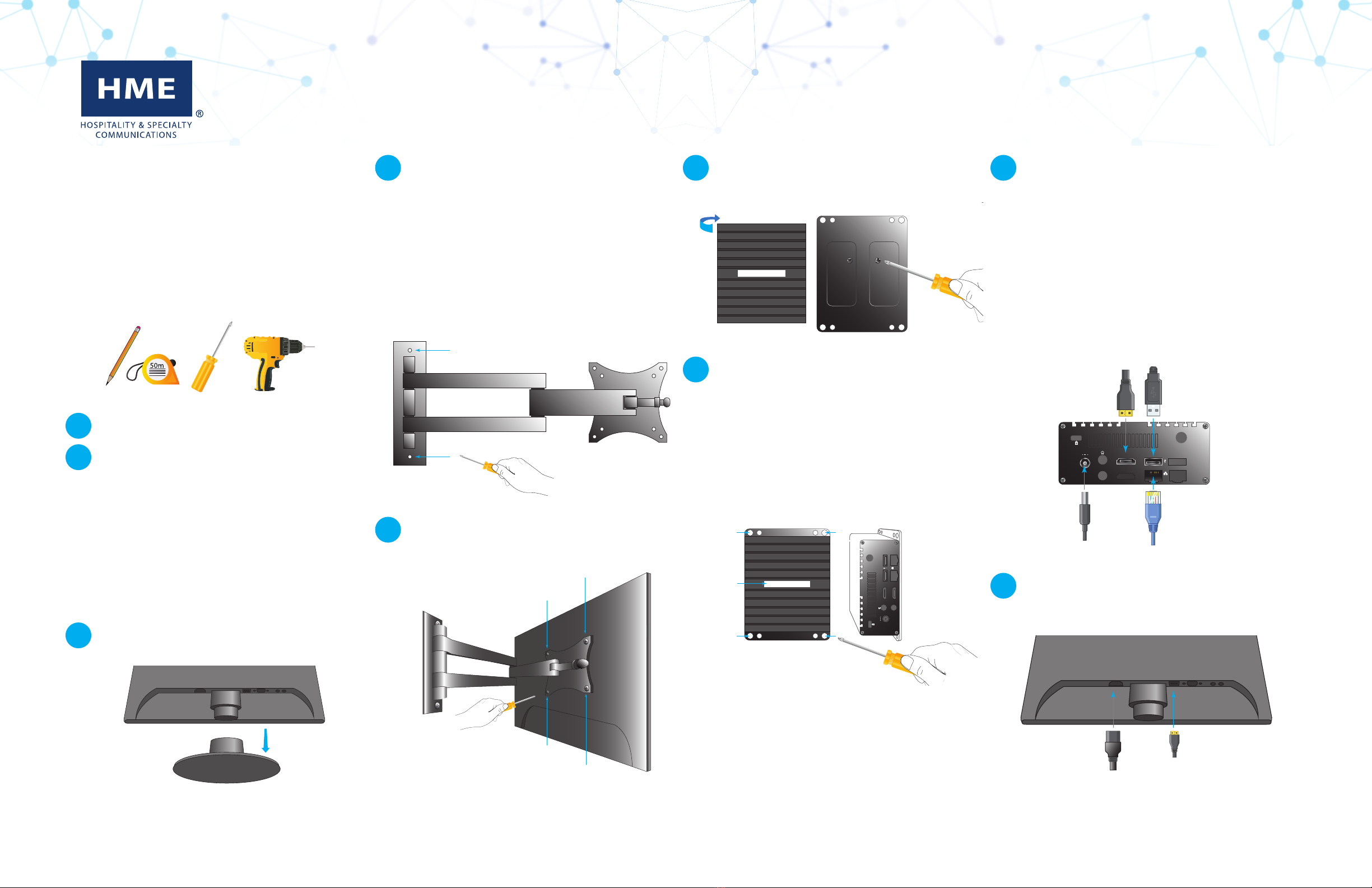
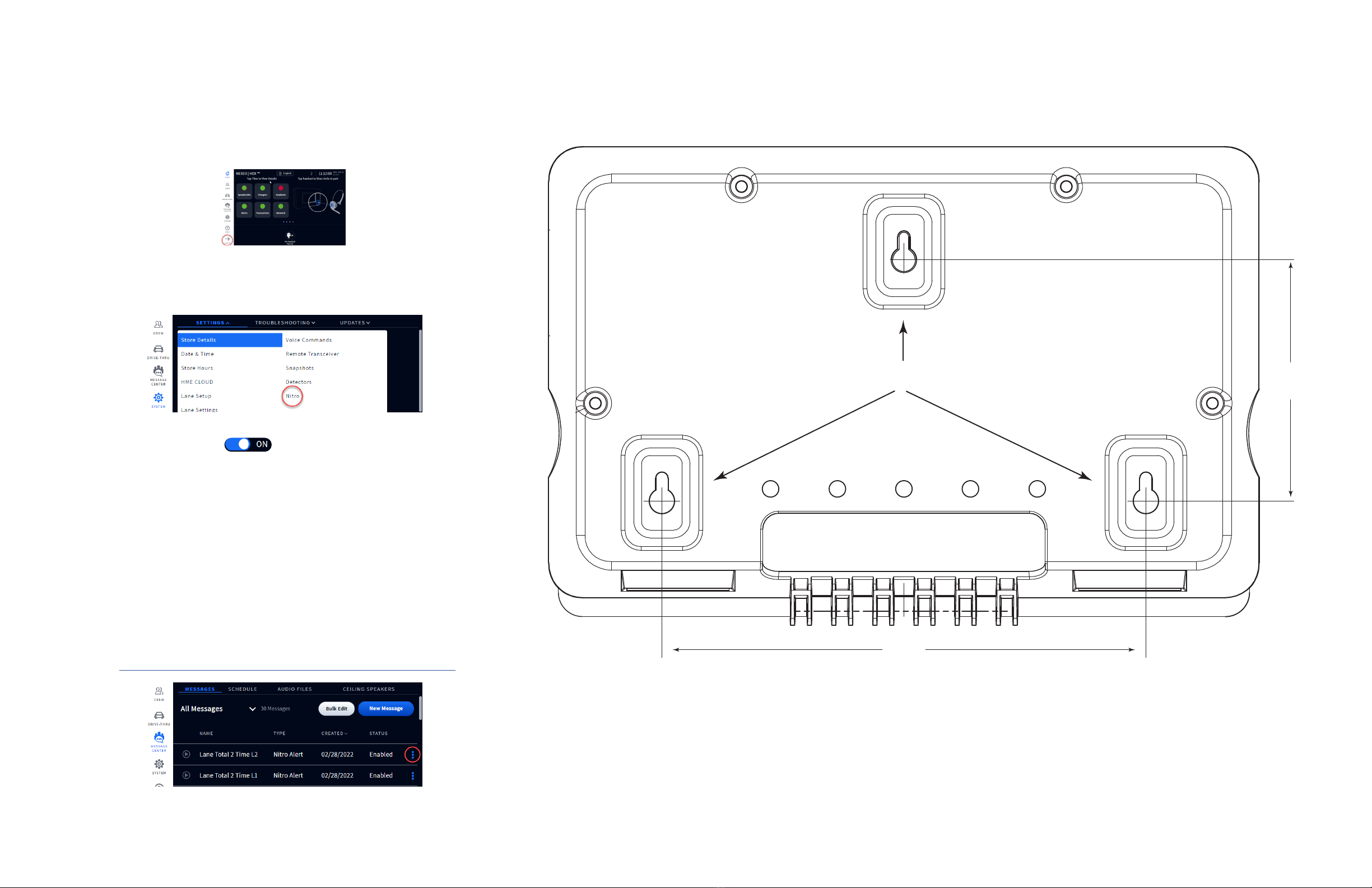
10. Mount the TSP60 using the three mounting
keyholes at the rear of the unit. The two lower
keyholes can be accessed by opening the lower
front cover of the housing. The latch is magnetic,
use the finger tabs on both sides and pull back
from the housing to open (see Fig. 2.1).
• Use the TSP Template image on the last page
of this guide to punch through and mark all
three mounting keyholes on the wall (the top
hole cannot be accessed through the TSP
housing).
• Drill three holes at the marked locations.
• Install the provided hardware (screws and
wall anchors if necessary) but do not tighten
the screws. Leave a gap (~ ¹/8th inch (3.2
mm)) between the screw heads and wall.
3”
(76.2 mm)
WALL
FINGER TAB
(both sides)
PULL To OPEN
TSP 60
SIDE VIEW
TSP60
SIDE VIEW
CLOSED OPENED
SCREW
(x3)
ANCHOR
(x3)
Fig. 2.1
• Align the keyholes to the screw heads.
• Mount the TSP60 over all three screw heads
until flush against the wall, then slide down
onto the screw shanks to secure it in place.
11. Route and terminate component cables to the
TSP60 through the opening on the rear housing.
Refer to the TSP Wiring Connections and Fig. 3.1
on page 3 while following these next few steps.
12. Connecting Loop Detectors:
After the Base Station has been connected to
the TSP, connect the first loop detector cable to
the LOOP1 connector (J4) of the TSP using Red
and Black wires. These may be connected in any
order (see Fig. 2.4). Any additional loops after
the menu point, such as a pickup window or a
pull-forward spot, can be connected to LOOP2,
3, and 4 connectors (J5, J6, and J7), respectively.
Note: Activation is required to use LOOP2 - 4.
13. When connecting a base station, choose one of
the following steps: A, if connecting a NEXEO|H-
DX™ Base Station to the TSP, or B, if connecting
an EOS|HD®Base Station to the TSP. Also, refer
to Fig. 3.1 wiring connections on page 3.
A For NEXEO: Connect the Green and White
wires from J800-1&2 on the base station to
the Greet1 terminals J1-1&2 on the TSP (see
Fig. 2.2). With polarized terminals, always
connect +ve to +ve and -ve to -ve. Connect
the Shield wire to ground (pin 5 on J800 &
J1). Connect the remaining Red wire from
J800-7 to J2-1 and Black wire from J800-6 to
J2-2 (or any of the available detector inputs).
For stores with another menu (e.g., a Y-Lane),
repeat this step using J801 on the base sta-
tion to Greet2 and another detector input on
the TSP.
8 7 6 5 4 3 2 18 7 6 5 4 3 2 1
1 2 3 4 5 6 7 81 2 3 4 5 6 7 8
NEXEO
Base Station
J801
LANE 2 TIMER
J800
LANE 1 TIMER
ZOOM Nitro
TSP60
J2 EXT. DETECTOR INPUTS
J1 GREET INPUTS
8 7 6 5 4 3 2 18 7 6 5 4 3 2 1
1 2 3 4 5 6 7 81 2 3 4 5 6 7 8
NEXEO
Base Station
J801 LANE 2 TIMERJ800 LANE 1 TIMER
ZOOM Nitro
TSP60
J2 EXT. DETECTOR INPUTS
J1 GREET INPUTS
Fig. 2.2
B For EOS: Connect the Green and White
wires from J6-7&8 on the base station to the
Greet1 terminals J1-1&2 on the TSP (see Fig.
2.3). With polarized terminals, always con-
nect +ve to +ve and -ve to -ve. Connect the
Shield wire to ground on both ends. Connect
the remaining Red wire from J1-4 to J2-1
and Black wire from J1-3 to J2-2 (or any of
the available detector inputs). For stores with
another menu (e.g., a Y-Lane), repeat this
step (for Greet 2 and Menu 2) and connect to
Greet2 and another detector input on the TSP.
1 2 3 4 5 6 7 81 2 3 4 5 6 7 8
1 2 3 4 5 6 7 81 2 3 4 5 6 7 8
EOS
Base Station
J6 MIC AND SPEAKERJ1 MENU DETECT OUTPUT
ZOOM Nitro
TSP60
J2 EXT. DETECTOR INPUTS
J1 GREET INPUTS
1 2 3 4 5 6 7 81 2 3 4 5 6 7 8
1 2 3 4 5 6 7 81 2 3 4 5 6 7 8
EOS
Base Station
J6 MIC AND SPEAKERJ1 MENU DETECT OUTPUT
ZOOM Nitro
TSP60
J2 EXT. DETECTOR INPUTS
J1 GREET INPUTS
Fig. 2.3
14. Connecting the USB cable:
Connect the USB type B end to the TSP60.
Connect the other end to the Black (bottom)
USB port on the front panel of the CU60. The
TSP60 turns on automatically when the CU60
is powered on (see Fig. 2.4).
A B 1 2 3 4 5 6
7 8
GREET
POWER
EXTERNAL DETECTORS
ON-BOARD DETECTORS
TSP60
J8 GREET J6 EXT. DET IN J10 DET OUT
J4
LOOP5
J5
LOOP6
J6
LOOP7
J7
LOOP8
TSP60
FRONT VIEW CU60
END VIEW
COM
USB type B end
LOOP
DETECTOR
POWER LED turns on
When CU60 is powered on
USB type A end
Fig. 2.4
15. Use cable ties and the strain relief holes on the
TSP60 rear housing to bundle and strain relief
the cables exiting the unit at the rear.
16. Turn on the CU60 (if it was not turned on in step
14) and turn on the monitor using the power
button.
17. The ZOOM Nitro screen:
• When you first boot up the system, the Instal-
lation Wizard screen appears (see Fig. 2.5).
• The Installation Wizard walks you through
several screens. Fill in the required informa-
tion to progress to the next screen. For ex-
ample, on the second screen, you must scroll
through and read EULA page and click on the
Agree button to advance to the next screen.
When you reach the Network Settings screen,
enable “DHCP” to auto-populate the fields.
Finally, a Congratulations prompt completes
the Installation Wizard; click Done to exit. The
Dashboard now appears.
• Click the menu icon in the Dashboard’s up-
per left corner, choose the SECURITY option,
and log in as the Installer.
• Use the CAR DETECTION SETTINGS option to
configure system to the store’s layout. Use
the STORE and DASHBOARD SETTINGS options
to customize the system further based on the
customer’s preference.
Fig. 2.5
18. Your system is now ready for use.
• Refer to the ZOOM Nitro User’s Guide for
details on how to use the system.
• If there are any installation issues, call HME
Technical Support at 1.800.848.4468.
10
11
12
13
15
16
17
14
18
A
B

© 2022 HM Electronics, Inc. All rights reserved. 3
J3 Vehicle Detection Output
Pin # Label Description/wire color
1 VEH_DET_OUT1 Output signal from LOOP5 (at J4)
2 VEH_DET_OUT2 Output signal from LOOP6 (at J5)
3 VEH_DET_OUT3 Output signal from LOOP7 (at J6)
4 VEH_DET_OUT4 Output signal from LOOP8 (at J7)
5 GND
6 GND
J3 is for Vehicle Detection outputs to the Base Station
to support menu detection in the absence of an ex-
ternal VDB. These outputs are from the four Onboard
detectors.
LED state table
LED Status/Description
POWER Solid Blue and always on if the CU is on and connected to the TSP
GREET Solid Blue, only on when the host is speaking
EXTERNAL DETECTORS Solid Blue, only on when a detector is connected, and a vehicle is
detected at the corresponding detection point
ON-BOARD DETECTORS Solid Blue, only on when a detector is connected, and a vehicle is
detected at the corresponding detection point
J2 External Detector Inputs
Pin # Label Description/wire color
1 EXT_IN1/RLY_NO From NEXEO Base Station: J800-7 or
EOS Base Station: J1-4, +ve Menu
Det. wire. (Red wire)
2 GND/RLY_COM From NEXEO Base Station: J800-6 or
EOS Base Station: J1-3, GND Menu
Det. wire. (Black wire)
3 EXT_IN2/RLY_NO
4 GND/RLY_COM
5 EXT_IN3/RLY_NO
6 GND/RLY_COM
7 EXT_IN4/RLY_NO
8 GND/RLY_COM
J2 supports four external detector inputs. These in-
clude both relay closure and logic-level signal inputs
in support of non-HME, wireless or generic detectors,
including positive polarity signal compatibility.
J1 Greet Inputs
Pin # Label Description/wire color
1 GREET1+ From NEXEO Base Station: J800-1 or
EOS Base Station: J6-8, +ve Outside
Mic/Speaker wire. (Green wire)
2 GREET1- From NEXEO Base Station: J800-2 or
EOS Base Station: J6-7, -ve Outside
Mic/Speaker wire. (White wire)
3 GREET2+
4 GREET2-
5 GND Ground/Shield wire from either Base
Station
6 /ALT_GREET1
7 /ALT_GREET2
8 GND
J1 supports two greet signal inputs from the Base
Station. Standard greet signals received from the
audio lines (speakers) are terminated at GREET1 and
GREET2 inputs. The ALT GREET 1 & 2 inputs are for
digital inputs from other sources, such as using a
headset button. Two greet signals is the maximum
supported at the same time. Both can be from the
same source or can be a combination of two sources
such as GREET1 and ALT GREET2.
J4, J5, J6, J7 Onboard Detector Inputs
Pin # Label Description/wire color
J4-1 Loop 5 +ve Menu point/first detector loop in Lane
J4-2 Loop 5 -ve
J5-1 Loop 6 +ve Additional loop after first detection point
J5-2 Loop 6 -ve
J6-1 Loop 7 +ve Additional loop after first detection point
J6-2 Loop 7 -ve
J7-1 Loop 8 +ve Additional loop after first detection point
J7-2 Loop 8 -ve
J4 is the default available onboard VDB for a direct
connection. Connect loop/wireless detector input
here.
In addition to accepting a direct detector connection,
these inputs (J4 - J7) can also be configured to sup-
port both relay closure and logic-level signal inputs.
J5 - J7 requires activation to use (call HME at the
phone number at the end of this guide for details).
A B 1 2 3 4 5 6 7 8
GREET POWER
EXTERNAL DETECTORS ON-BOARD DETECTORS
TSP60
J1 GREET J2 EXT. DET IN J3 DET OUT J4
LOOP5
J5
LOOP6
J6
LOOP7
J7
LOOP8
USB type B
OPENING for
CABLE ROUTING
CONNECTOR
LABELS
PCBA SN
LABEL
LED
PANEL
MOUNTING
KEYHOLE
MAGNETIC
LATCH
TSP60
FRONT VIEW
BOTTOM HALF OPENED TO EXPOSE CONNECTORS
HOLES for
CABLE TIES/
STRAIN RELIEF
Lorem ipsum
Fig. 3.1
Fig. 3.2
A copy of this guide and much more can be found by scanning
this QR code or going to:
https://www.hme.com/qsr/drive-thru-user-manuals/
HM ELECTRONICS, INC.
2848 Whiptail Loop, Carlsbad, CA 92010 USA
Phone: 1-800-848-4468 | Fax: 858-552-0172
The HME logo and product names are registered
trademarks or trademarks of HM Electronics, Inc.
tsP WIrIng ConneCtIons
PCBA SN Label: This serial number
identifies the TSP60 if more than
one is used. It can be found under
TSP SETTINGS>TSP60 on the
ZOOM Nitro display (see Fig. 3.2).
Connected
Reset Remove

© 2022 HM Electronics, Inc. All rights reserved.
4
.
6.00”
(152.4 mm)
3.00”
(76.2 mm)
TSP60
TEMPLATE FOR MOUNTING HARDWARE
This way up
Three mounting keyholes
1. On the NEXEO|HDX base station HOME screen (see Fig. 4.1), log in to
the base station using the four-digit Installer’s PIN.
Fig. 4.1
2. Navigate to the SYSTEM screen, and from the SETTINGS drop-down
list, select “Nitro.” See Fig. 4.2.
Fig. 4.2
3. Tap Nitro Alerts toggle to enable alerts and then configure:
Nitro MQTT IP: Specifies the assigned IP address for ZOOM Nitro.
Log in to the ZOOM Nitro dashboard and go to NETWORK>LO-
CAL NETWORK. Copy the listed IP Address and enter here.
Nitro MQTT Port: Specifies the assigned port for Nitro MQTT bro-
ker. The default port number is 1883.
Nitro MQTT Keep Alive Interval: Specifies the keep message alive
interval in seconds (range = 1 - 120), the default is 10 seconds,
this means system messaging is set to occur every 10 seconds.
4. Navigate to the MESSAGE CENTER screen, and under the MESSAGES
tab, find Nitro Alerts listed under the TYPE column (see in Fig. 4.3).
5. Use the More icon at the end of each row to enable/disable or edit
alerts. For example, Fig. 4.3 shows the first two Nitro Alerts enabled.
Also see the online document “Configuring ZOOM Nitro to NEXEO
Alerts” for more details. It can be found here:
https://www.hme.com/training/supporting-documents/?lng=1
Fig. 4.3
ConfIgurIng neXeo|HDX for ZooM nItro use
(If requIreD)
Other HME Conference System manuals

HME
HME SYS6700HD Specifications

HME
HME SYS6700HD User manual

HME
HME IC300 User manual

HME
HME NEXEO HDX User manual

HME
HME EOS HD User manual

HME
HME NEXEO HDX User manual

HME
HME Communicator COM6000 User manual

HME
HME NEXEO HDX User manual

HME
HME Wireless 6400 User manual

HME
HME Clear-Com HelixNet Partyline User manual
Popular Conference System manuals by other brands

Cornell
Cornell 4800 series installation manual

DETEWE
DETEWE DSL Speedweb OpenAttendant 205 user guide

Aastra
Aastra OpenCom 100 series Quick reference guide

Mocet
Mocet IG7600 Quick installation guide

Studiomaster
Studiomaster Vak 10c instruction manual

Polycom
Polycom RealPresence Practitioner Cart 8000 user guide