Hobby King Turnigy 10XC User manual

Turnigy 10XC Charger
User’s Guide
© Copyright 2012 Hobby King
01/17/2012
This Turnigy product manufactured in Singapore by LEO Energy Pte Ltd, www.revolectrix.com

January 17, 2012 ver 1.0 www.revolectrix.com 2
Table of Contents
Table of Contents........................................................................................................................2
Description..................................................................................................................................3
Features.......................................................................................................................................3
Precautions .................................................................................................................................5
Parts.............................................................................................................................................5
Charger terminology...................................................................................................................6
Power and Charging Speed .......................................................................................................7
About Factory Presets...............................................................................................................................8
Setting Input Current Limit and Low Voltage.............................................................................................8
Connecting packs to the charger..............................................................................................9
General information...................................................................................................................................9
Connecting packs......................................................................................................................................9
Applying power to the charger................................................................................................10
Introduction to presets.............................................................................................................................10
Operating the charger ..............................................................................................................11
Overview of button operations:...............................................................................................................11
Performing Common Tasks:....................................................................................................12
Selecting a preset ...................................................................................................................................12
Changing a preset...................................................................................................................................12
Charging a pack or packs .......................................................................................................................14
Options Menu Explained.........................................................................................................................15
Alternate charging modes.......................................................................................................................17
Using the Firmware Update Utility Software ..........................................................................19
Installing the Firmware Update Utility Software......................................................................................19
Launching the Firmware Update Utility Software....................................................................................19
Connecting the charger to your computer...............................................................................................19
Updating charger firmware......................................................................................................................19
Restoring Factory Defaults......................................................................................................................19
Balance connector wiring ........................................................................................................20
When using DEFAULT WIRING mode (Factory Default Setting) ...........................................................20
When using XH/EH WIRING mode.........................................................................................................22
Specifications............................................................................................................................24
Quick start for the Turnigy 10XC Charger ..............................................................................25
Troubleshooting........................................................................................................................26

Description
Model: Hobby King Turnigy 10XC, for use with LiPo, Li-Ion, A123, NiCd, NiMH, and Pb battery
packs
10s Multi-Chemistry, 10 Amp, 400W model for charging with available high-power balancing, overcharge
protection, and automatic charge/discharge to storage (for Li batteries)
Features
Charges Lithium Polymer, Lithium Ion, A123, NiCd, NiMH, and Pb packs. Charges any brand of
pack.
Supports high-power balance charging of Li or A123 battery packs. Balance charges one 1s to 10s
pack, or two 1s to 5s LiPo packs simultaneously. When two packs are connected, the balance
connections and pack main discharge wires are wired in series by the charger.
Equipped with JST PA series times two, 6 position balance connectors which enable the charger to
monitor and independently charge each cell to its optimum level (balance charge operation).
Accepts Turnigy 10XC Adapters for plug-and-play compatibility. Turnigy 10XC Adapters support
from 2s to 6s battery packs (all brands) when the charger is running in the charger’s default wiring
mode; termed “DEFAULT WIRING” in charger options menu. See section titled “Special Button
Operation” later in this user guide for more details on altering WIRING MODE.
Also supports customer-selectable, XH mode. JST XH/EH balance connectors and wiring are
growing to be the dominant scheme in the industry. Switching to XH mode, the Turnigy 10XC can
support existing XH style adapters you may already own. Splice in Turnigy 6 position battery
pigtails to the wires on existing adapters and you are good to go!
Supports non-balanced charge of Li (up to 2s), Ni (up to 28 cells), Pb (up to 24V), A123 (up to 12s).
Accepts 10-32 VDC input.
Up to 10A max charge current.
Maximum 25A input current
470W max continuous input and 400W max continuous output at 30V DC input. Charger will achieve
rated output to a 10s LiPo using 30V DC input. Increasing input voltage beyond 30V does increase
power output, but only if the charger’s output voltage exceeds 42V; e.g., when charging 12s non-
balanced A123 packs. However, 32V DC input is a maximum rating. It is recommended to utilize
input voltage slightly below the absolute maximum.
Includes 1A proportional integrated balancers
Power-balance-charge packs through balance connectors in tandem with the main discharge wires of
the battery pack(s). Unit does not support balance-connector only charging.
Compensates for balance wire lengths up to six feet with 1mV accuracy.
Displays individual cell internal resistance to 0.1milliohm, for estimating pack quality, health, and
performance.
Storage Preset available to charge or discharge Li batteries to appropriate per-cell storage levels; 3.8v
(LiPo), 3.0v (A123).
During discharge to storage, the 10XC incorporates 1A-per-cell (nominal) discharge rate using the
charger’s integrated balancing circuitry to provide up to 42W (at 10s) discharge power.
Light-grey, 2 line, 16 character backlit LCD display provides easy readability.
One button, Charge Optimization can be set for an Accurate 1mV cell balance and (C/20 termination)
January 17, 2012 ver 1.0 www.revolectrix.com 3

or for Faster Charging (less balancing accuracy and C/10 termination) at the 10XC interface.
Protects your Pb input source from over-discharge by providing an audible warning when input
voltage of your Pb battery approaches 50% state of charge.
Intelligent controller performs extensive checks to prevent damage to packs and power supply. This
makes it virtually impossible to damage the charger or the batteries from incorrect connections or
wiring; including, but not limited to reverse polarity.
Input reverse-polarity protection.
Simple, effective, 2-button interface allows instant access to presets, preset parameters, and starting
and stopping charger operations.
Access pre-defined, named presets by clicking the MODE button.
Hold the MODE button to access the Main Menu operations: Choose Chg. Amps, Choose Chemistry,
Show Help Screen, Exit. Use the charger’s Main Menu to alter basic settings of presets on-the-fly.
Press and hold the START/STOP button to start charger operation or cancel/end a charging session.
Press and hold MODE button during power up to access Options Menu; choose input amps limit and
supply low voltage setting (Power Management feature), alternate between DEFAULT or XH balance
wiring schemes, and set quiet charging (no speaker beeps during charging).
Supports Bi-directional, optional PC which enables charger firmware updates.
Use available PC software to update charger firmware reliably with the click of your mouse button,
and without sending the charger back to the factory. Keep up-to-date with the latest enhancements
and bug fixes.
Works with a wide range of power supplies, even those not rated for high power. Easily changes
from moderate current bench supply at home to car battery at the field. Set Input supply amps limit
and supply low voltage at the charger interface, to prevent damage to your input source.
January 17, 2012 ver 1.0 www.revolectrix.com 4

Precautions
Follow all instructions in this manual to assure safe operation.
IMPORTANT: Do not disconnect or connect packs while the charger is charging.
Always watch LiPo packs while they are charging. Never leave LiPo packs unsupervised during
charging.
See additional warning sheets provided with your battery packs.
Follow all guidelines for charging, discharging, handling and storing LiPo cells.
Minor arcing may occur when discharge wires are connected to the charger before charging. This is
normal.
Parts
Turnigy 10XC Charger
Removable input plier clips (red/black) for connecting the 10XC to a DC power source
Optional PC USB Adapter (required for using the Firmware Update Utility Software)
Optional: Turnigy 10s Adapters (support all major battery brands)
Optional: Turnigy 10s Banana Plug Output Cables (2 pack) – solder the mating end of the connector
you use on your battery’s discharge wires to these cables
Notes:
You may have already received some of the optional items listed above with your purchase.
January 17, 2012 ver 1.0 www.revolectrix.com 5

Charger terminology
To DC
Power
Supply
DisplayConnect PC USB Interface here when
connecting to PC Firmware Update Software
(black wire toward outside wall of case) Channel 1 Channel 2
Banana jacks for discharge
wires when charging
2 packs at the same time
Use two outer banana jacks for discharge
wires when charging only one pack.
Never connect pack discharge wires
across the two yellow banana jacks.
This will result in blowing the internal fuse.
Note the red “X” warning between the yellow jacks!
MODE
button
START/STOP
button
Channel 2
balance connector
Channel 1
balance connector
January 17, 2012 ver 1.0 www.revolectrix.com 6

Power and Charging Speed
When one pack is connected to the charger, the pack is initially charged at the selected charge rate (or
the maximum charge rate possible). Using Ohm’s law, the maximum charge rate (Amps) is derived
from the maximum power (Watts) the charger can produce without overheating.
Maximum output power will normally reach approximately 400W when charging a 10s LiPo battery
using a 30V DC input power source, and assuming the input source can deliver a maximum of 470W of
clean power to the charger input. Maximum power depends on many factors including pack imbalance
during charge, input (supply) voltage, output (charge) voltage, DC/DC converter efficiency, which
varies between 80% and 95% depending on the relationship of supply voltage-to-charge voltage,
ambient temperature, and internal operating temperature. Increasing input voltage beyond 30V does
increase power output, but only if the charger’s output voltage exceeds 42V; e.g., when charging 12s non-
balanced A123 packs. However, 32V DC input is a maximum rating. It is recommended to utilize input
voltage slightly below the absolute maximum.
When the pack reaches about 95% capacity, the charger enters balance charge mode. Charge current
tapers off, but will remain at 1A or higher until the pack voltage slows the current to 1/20th C (Constant
Voltage Mode). When the pack reaches 99% capacity, the charger beeps three times. The pack can be
removed to use, or allowed to continue charging until it is 100% full and the charger displays “Charge
Complete.”
During the entire charge process, the charger power balances the pack using 1A current until all cell
voltages are within 1mV of each other. Power balancing is the process of beginning the balancing
process early in the charge cycle using high-current shunts to drain excess cell voltage while other cells
in the pack have a chance to catch up. Power balancing means the pack tops off faster and the total
charge time is greatly reduced. This is possible because the balance circuitry is internal to the charger.
Automatic temperature control and an integral fan ensure the charger never exceeds maximum safe
operating temperature under any conditions. The result is faster, safer charging.
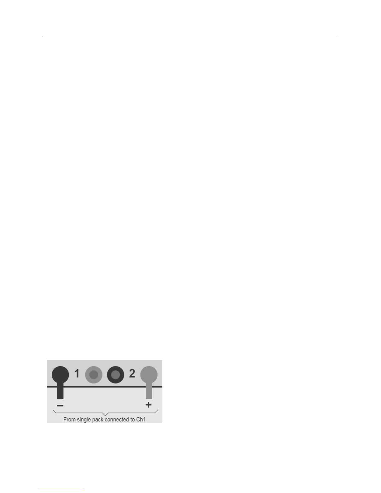
When charging two packs, the packs are connected in series (the balance connections as well as the
main charge wires). In effect, the charger treats the two packs as a single pack. For example, if you
connect a 3s pack and a 4s pack, the charger operates on them as one 7s pack. If the pack capacities are
different for the two packs connected, the charge rate should be selected based on the lower capacity
pack. Initially, the packs are charged at the selected charge rate (or the maximum charge rate possible)
until one pack becomes fully charged—however, the charger can handle cell balancing of the two packs
completely independently. The second pack continues to charge at a minimum 1A rate until it is full
and balanced.
Notice that one of the packs in a simultaneously-charged pair is always topped off at a minimum rate of
1A (dictated by the maximum balance current available). If the packs have the same capacity, and were
discharged to about the same level, both packs will charge in less than 30 minutes at 3C. However, if
the packs have different capacities, or were discharged to different levels, charging for the pair could take
longer than expected. In most instances, by the time the first pack is fully charged, the second pack is
already approaching constant voltage charge mode; the battery pack itself is the limiting factor in charge
time, not the charger.
Example 1: You are powering an aircraft with two 4s 2100mAh packs connected in series.
Because those packs have the same capacity, and were discharged to about the same level
during flight, you can expect them to charge in about the same time. It would be appropriate
to charge them simultaneously using the Turnigy 10XC Charger.
Example 2: You are powering one aircraft with a 3s 500mAh pack, and other aircraft with a
5s 5000mAh pack. If you charge these packs simultaneously using the Turnigy 10XC
Charger, it would probably take a long time (the 500mAh pack would become full first, then
the charger would switch to its 1A balancing rate to fill up the 5000mAh pack, which could
take several hours). In this case, it would be faster to charge these packs separately because
the charger can then apply optimum (and substantially different) charge currents to each pack.
January 17, 2012 ver 1.0 www.revolectrix.com 7

In some cases, such as Example 2, it will be faster to charge two packs separately rather than
simultaneously. It’s up to you to decide, based on what you know about their respective capacities and
discharge states.
In Example 2 above, when the 500 mAh pack reaches 99% capacity (the charger beeps three times), it is
a simple matter to remove the pack from the charger and continue charging the 5000 mAh pack at a
higher charge rate. Here’s how:
1. Connect both packs and start charging them using an AUTO or manual rate setting.
2. Watch the fuel level display. When one pack reaches 99% fuel level, stop charging.
3. Disconnect the full pack.
4. If the partially charged pack is connected to Channel 2, move it to Channel 1.
5. Continue charging the partially-charged pack.
About Factory Presets
During all phases of the charge process, the charger will balance all the cells in Channel 1 and Channel 2
together as one big pack, and report the fuel level of two packs being charged as one big pack. The
exception to this is if you use one of the Factory containing the words “Dual Channels”. In this case, the
10XC will balance all the cells in Channel 1 against each other and all the cells in Channel 2 against each
other.
Setting Input Current Limit and Low Voltage
The charger will draw up to 25A to deliver its 10A maximum output current. The high input current is
required when the input voltage must be boosted to drive packs having larger numbers of cells in series.
Output power is determined by several factors, including battery pack imbalance during charge, input
voltage, input current, output voltage, ambient temperature, and the charger’s internal temperature.
The charger’s DC-to-DC converter is typically 80% to 95% efficient. Highest efficiency occurs when
the input voltage is higher than the output voltage needed to charge the connected pack(s). However,
the charger cannot tolerate input higher than 32V DC. Supplying input voltage of 30V provides the
highest efficiency, coolest operating temperature and fastest charging times, especially when charging
packs containing more than five cells in series.
You can also manually limit the charger’s input current and adjust the supply low voltage limit so the
charger will not draw more power than the supply can provide. If you know your power supply is rated
for 3A output, for example, you can limit the charger’s input current to 3A. (Be aware that limiting
charger input current may increase pack charge times.) If you are using a Pb battery to power the 10XC
and you do not want to discharge below a certain voltage, you can set it where you want it. When the
charger is powered from a high current source (such as a car battery), you can adjust the current limiting
to provide maximum pack charging current. Details for changing these settings are provided in sections
“Options Menu Explained” as well as “Limiting charger input current”. The Factory Default settings
for Input Current Limit and Supply Low Voltage Limit are as follows:
1. Input Supply Current Limit: 25A
2. Input Supply Low Voltage Limit: 11V
January 17, 2012 ver 1.0 www.revolectrix.com 8

Connecting packs to the charger
General information
When balance charging, both a balance connector and the main discharge wires must be connected to
the Turnigy 10XC.
When performing a non-balance charge on a 2s Li, A123, NiCd, NiMH, or Pb pack, connect only the
pack’s main discharge wires to the two outer banana jacks on the charger’s front panel.
When charging only one pack, always plug that pack’s balance connector into the charger’s Channel
1 balance port and always connect the main discharge wires to the charger’s outermost banana jacks.
When charging two packs simultaneously, make sure to correlate each pack’s balance connector and
pack discharge leads to the same charger Channel. For example, first pack’s balance connector in
Channel 1 balance port, first pack’s discharge leads to Channel 1 banana jacks (the left two jacks).
Second pack’s balance connector in Channel 2 balance port, second pack’s discharge leads to
Channel 2 banana jacks (the right two jacks).
When charging two packs, both packs must have the same chemistry. For example, you can’t charge
one A123 pack and one LiPo pack at the same time. Never mix chemistries under any circumstances.
WARNING: Failure to comply with the above could result in fire and/or damage not covered by warranty!
Pack discharge wires are usually not terminated in banana plugs (e.g., they might be terminated in a
XT60 connector). For convenience in connecting to the charger, prepare an adapter cable with
banana plugs on the charger end and a connector that mates with the pack’s discharge connector on
the other end.
CAUTION: When using the banana plug adapter cables described above, ALWAYS insert the banana
plugs into the charger BEFORE connecting the adapter cable to the pack. Reverse the sequence when
disconnecting the pack. This will prevent the live banana plugs from touching each other, which would
create a dangerous condition and could seriously damage the pack.
Connecting packs
1. Hobby King offers plug-and-play adapters for charging LiPo packs equipped with balance connectors
made by all major manufacturers.
If an adapter isn’t available for the pack you want to charge, or if the pack doesn’t have a balance
connector, the Turnigy 10XC 6 position cable assemblies can be used to make the pack compatible with
the Turnigy 10XC Charger.
Note: see also “Balance connector wiring” later in this manual.
2. When charging a single pack, plug the discharge wires into the outermost banana jacks.
January 17, 2012 ver 1.0 www.revolectrix.com 9

3. When charging two packs simultaneously, connect the discharge wires into the banana jacks as shown
below.
Applying power to the charger
To apply power to the charger: Connect the charger to a 10V to 32V DC power supply, field battery
or car battery. If your bench power supply is equipped with banana jacks for output, you can remove
the plier clips from the charger’s input cables and plug the cables directly into the power supply jacks.
When the charger is powered up, it displays the following “Welcome” screen:
Turnigy 10s
[firmware version]*
Press the MODE button one time to advance to the “Preset Menu”
Preset 1
[chem] [BAL] @ [charge current]*
Press the MODE button repeatedly to scroll through and view/select the Turnigy 10XC’s 10 presets,
one at a time.
*Information in square brackets varies.
Introduction to presets
As shipped from the factory, the charger has ten presets. The presets are displayed in the “Preset Menu”
and display in the charger’s LCD as follows:
Preset Name/Settings Description
Preset 1
LiPo BAL @ 1.0A
Designed for a single 1s-10s LiPo battery, balance
charged at 1.0 Amps.
P2 Dual Channels
LiPo BAL @ 1.0C
Designed for two, 1s-5s LiPo batteries, balance
charged at 1.0 Amps.
Preset 3
LiPo BAL @ STORE
Designed to automatically storage charge or discharge
LiPo batteries to 3.8v per cell for safe storage.
Preset will charge or discharge using 1A internal
balance circuits.
Preset 4
LiPo 2sU @ 1.0A
Designed for one 2s LiPo, unbalance charged at 1.0A.
Preset 5
A123 BAL @ 4.6A
Designed for 1s-10s A123 battery, balance charged at
4.6A.
P6 Dual Channels
A123 BAL @ 4.6A
Designed for two, 1s-5s A123 batteries, balance
charged at 4.6A.
Preset 7
A123 2sU @ 4.6A
Designed for one 2s A123, unbalance charged at 4.6A.
January 17, 2012 ver 1.0 www.revolectrix.com 10

Preset 8
NiCd 8mV @ 1.0A
Designed for 1-26 cell NiCd, non balance charged, peak
detection, 8mV fallback at 1.0A.
Preset 9
NiMH 5mV @ 1.0A
Designed for 1-26 cell NiMH, non balance charged, peak
detection, 5mV fallback at 1.0A.
Preset 10
LEAD 12V @ 3.0A
Designed for 12V Lead Acid Battery, non balance
charged at 3.0A.
When power is applied, the charger always initializes to the last preset used for charging. If you altered
the charge settings for a preset at the charger (as described in “Changing a preset,” later in this manual),
those changes are retained when the charger is disconnected from power, and will be reapplied when the
charger is powered up again.
“Selecting a preset” and “Changing a preset,” in the next section, provide additional information.
Operating the charger
You operate the charger using the MODE button and START/STOP button on the right side of the
charger. This simple, effective, 2-button interface allows instant access to presets, preset parameters, as
well as starting and stopping charger operations.
MODE button: enables you to view/select a preset, change preset parameters and display charging
data during charging.
START/STOP button: enables you to start charging after you have selected a preset, and to stop or
cancel a charging session at any time. The START/STOP button also allows you to toggle back and
forth between Accurate and Faster Charge optimizations (applicable to LiPo and A123 battery packs
only).
Overview of button operations:
Following is an overview of all possible functions available using these buttons. These functions are
listed in the approximate order you might use to traverse the 10XC.
At start up, press the MODE button to access and scroll the Preset Menu and to view/select pre-
defined, named presets and their settings, one at a time. A preset is considered “selected” when its
name and settings are listed on the charger’s LCD.
At any time prior to starting a charge operation, press and hold the MODE button to access the
Main Menu options: Choose Chg. Amps, Choose Chemistry, Show Help Screen, Exit.
While watching the scrolling menu options, continue holding the MODE button, then, release it
only when you see the menu option you want. Now you may use the charger’s menu to alter
parameters of presets on-the-fly. Note: Preset parameters are permanently saved the instant they are
changed.
When inside of Main Menu options, press the MODE button to change preset parameters.
When changes to preset parameters are complete, press and hold the MODE button to access the
Main Menu again. Then choose Exit to return to the Preset Menu.
Press the START/STOP button to toggle back and forth between Accurate vs Faster Charge
optimization. This feature available only when a LiPo or A123 balanced preset is selected.
Press and hold the START/STOP button (for 1 second) to start charger operation or cancel/end a
charging session.
At any time while charge is in progress, press the MODE button to view real-time operating
January 17, 2012 ver 1.0 www.revolectrix.com 11

information and charging data.
Special Button Operation:
Press and hold MODE button while applying power to access and scroll the Options menu: CHOOSE
SPLY AMPS, LOWS SUPPLY VOLTS, NODE CONNECTOR, QUIET CHARGING, Exit. Use the Options
Menu to choose input amps limit and supply low voltage setting, alternate between DEFAULT or XH
balance wiring schemes, and set quiet charging (no speaker beeps during charging).
Performing Common Tasks:
Selecting a preset
At start up, press the MODE button to access and to scroll the Preset Menu and view/select pre-
defined, named presets and their settings, one at a time.
The preset displayed when you stop pressing the MODE button is the “selected” preset. Once the preset
is selected, you can change the parameters for this preset (see “Changing a preset”) or begin charging by
pressing and holding the START/STOP button (for one second).
Changing a preset
You can change the charge parameters for the currently selected preset to match the characteristics of
the pack(s) you are charging.
At any time prior to starting a charge operation, press and hold the MODE button to access the
Main Menu options: Choose Chg. Amps, Choose Chemistry, Show Help Screen, Exit.
While watching the scrolling menu options, continue holding the MODE button, then, release it
only when you see the menu option you want. Now you may use the charger’s menu to alter
parameters of presets on-the-fly. Note: Preset parameters are permanently saved the instant they are
changed.
1. Select the preset you want to change (see “Selecting a preset,” above).
2. At this point, there are several things you can do:
To change the charge current:
a. Press and hold the MODE button, then release it when the display changes to this:
Choose Chg. Amps
Hold for More
Note: If you hold the MODE button down longer, you’ll see Choose Chemistry,etc (described
below)
When you
release the MODE button, you’ll see the charge current of the selected preset:
Choose Chg. Amps
Charge @ [current]
b. Then:
Press the MODE button about once per second to increase current in 0.1A steps.
Press the MODE button quickly twice to increase current to the next whole Amp.
January 17, 2012 ver 1.0 www.revolectrix.com 12

When the maximum current is reached, press the MODE button once if you wish to select
STORAGE charge mode:
STORE (to charge or discharge pack to 50% capacity; optimum for long-term storage)
To change the chemistry:
a. Press and hold the MODE button, then release it when the display changes to this:
Choose Chemistry
Hold for More
Note: If you hold the MODE button down longer, you’ll see Show Help Screen, etc (described
below).
When you release the MODE button, you’ll see the chemistry setting:
Choose Chemistry
[chemistry] [BAL] [voltage]
b. Press and release the MODE button until you see the chemistry you want. Choices are:
Chemistry/Charge Mode Description
LiPo BAL 4.20V LiPo Balance Charge to 4.20V per cell
LiPo BAL 4.22V LiPo Balance Charge to 4.22V per cell
LiPo BAL 4.10V LiPo Balance Charge to 4.10V per cell
A123 BAL 3.65V A123 (or LiFe) Balance Charge to 3.65V per cell
NiCd 8mV Fall Bk NiCd Unbalance Charge, Peak Detect, 8mV Fallback
NiMH 5mV Fall Bk NiMH Unbalance Charge, Peak Detect, 5mV Fallback
LEAD 6V Lead Acid Charge to 6V
LEAD 12V Lead Acid Charge to 12V
LEAD 18V Lead Acid Charge to 18V
LEAD 24V Lead Acid Charge to 24V
LiPo 1sU 4.20V LiPo Unbalance Charge, 1s to 4.20V
LiPo 2sU 8.40V LiPo Unbalance Charge, 2s to 8.40V
A123 1sU 3.65V A123 (or LiFe) Unbalance Charge, 1s to 3.65V
A123 2sU 7.30V A123 (or LiFe) Unbalance Charge, 2s to 7.30V
A123 3sU 10.95V A123 (or LiFe) Unbalance Charge, 3s to 10.95V
A123 4sU 14.60V A123 (or LiFe) Unbalance Charge, 4s to 14.60V
A123 5sU 18.25V A123 (or LiFe) Unbalance Charge, 5s to 18.25V
A123 6sU 21.90V A123 (or LiFe) Unbalance Charge, 6s to 21.90V
A123 7sU 25.55V A123 (or LiFe) Unbalance Charge, 7s to 25.55V
A123 8sU 29.20V A123 (or LiFe) Unbalance Charge, 8s to 29.20V
A123 9sU 32.85V A123 (or LiFe) Unbalance Charge, 9s to 32.85V
A123 10sU 36.50V A123 (or LiFe) Unbalance Charge, 10s to 36.50V
A123 11sU 40.15V A123 (or LiFe) Unbalance Charge, 11s to 40.15V
A123 12sU 43.80V A123 (or LiFe) Unbalance Charge, 12s to 43.80V
To get help using the Turnigy 10XC: Press and hold the MODE button, then release it when the
display changes to this:
Show Help Screen
Hold for More
Note: If you hold the MODE button down longer, you’ll see Exit,etc (described below)
Press the MODE button repeatedly to scroll the Help Screen information
January 17, 2012 ver 1.0 www.revolectrix.com 13

To Exit the Main Menu and return to the Preset Menu: Press and hold the MODE button, then
release it when the display changes to this:
Exit
Hold for More
Note: You may press and hold the MODE button from any place within the menu to change menu
options or select Exit. Remember, any changes you make while in the Main Menu are saved the instant
you make the changes. If you hold the MODE button down longer, you’ll see the previous Main Menu
options described above.
or
To Quick Start a Charge (Exit the Main Menu and begin charging in one operation if a pack is
connected): Press and hold the START/STOP button for one second. Details are provided in the
next section.
Charging a pack or packs
1. Before charging, pack(s) must be properly connected to the charger. See “Connecting packs to the
charger,” earlier in this manual for details. Also, the correct preset must be selected for the packs
connected to the charger. See “Selecting a preset”, earlier in this manual for details.
2. Press and hold the START/STOP button for one second to enter Charging Mode.
3. You will see the following screens in sequence:
PLEASE WAIT…
CHRGING LiPo BAL
MODE for info.
*above screen will vary depending on what preset is being used
Note: because the 10XC supports automatic storage charge/discharge to 50%, the initial LCD
indication may show DSCHGING for up to 10 seconds, even if a charge was initiated. This is normal.
4. While in Charge Mode, you can take the following actions:
To view pack and operating data: Press the MODE button repeatedly to cycle through the
following screens. (These examples assume two packs are being charged using one of the Dual
Channel presets; if one pack is being charged, only the top line may appear in some screens.)
C 1.00A 00:00:59
Supply=12.2V/ 3A
Charge current and charge time.
Supply voltage and input current.
[preset name]
[chem] [BAL] @ [charge current]
Selected preset.
Preset’s charging settings.
[chemistry] [BAL] [charge process]
[chemistry] [BAL] [charge process]
Chemistry and charge process (Fast
Charging, Balance Charging, etc.) in effect
for each channel.
Ch1 Pack = 15.772V
Ch2 Pack = 15.761V
Total pack voltage(s).
January 17, 2012 ver 1.0 www.revolectrix.com 14

Ch1 42mAh In
Ch2 40mAh In
mAh put back into pack(s) during charging.
1:3.956V 2:3.956V
3:3.956V 4:3.956V
Individual cell voltages.* “:” indicates Ch1
screen auto scrolls to show all cells:
5=3.966V 6=3.966V
7=3.966V 8=3.966V
Individual cell voltages.* “=” indicates Ch2
1:12.3mΩ2:13.2
3:12.1mΩ4:14.2
Individual cell internal resistances in
milliohms.*† “:” indicates Ch1
screen auto scrolls to show all cells:
5=11.8mΩ6=13.5
7=12.4mΩ8=12.6
Individual cell internal resistances in
milliohms.*† “=” indicates Ch2
*Cells are numbered from 1 through n, where 1 is the first cell in the pack connected to Ch1, and n is the last cell in the pack
(if only one pack is being charged) or the last cell in the pack connected to Ch2 (if two packs are being charged).
†For the charger to calculate internal resistances, pack must be at less than 80% fuel level at start. Internal resistances will
be available for display after about 12 minutes of charging, and will be periodically updated after that.
5. Note, when you press and hold the START/STOP button to initiate a charge or storage operation
(step 2 above), you are actually starting a charge “session”. During a session, the data is logged to the
charger’s memory, the displayed on the charger’s LCD. When the charger is allowed to finish the
operation, the LCD will read, e.g., LiPo [BAL] DONE
To end the charge session and clear logged data: Press the START/STOP button for one second.
The charger flashes CHARGER STOPPED then displays the Preset Menu.
Note: Pack data is lost when you end the charge session, so if you want to see it, cycle through the saved
data by pressing the MODE button before pressing and holding the START/STOP button.
To cancel charging at any time: Press and hold the START/STOP button for one second. The
charger flashes CHARGER STOPPED then displays the Preset Menu.
Note: Pack data is lost when you end the charge session, so if you want to see it, cycle through the saved
data by pressing the MODE button before pressing and holding the START/STOP button.
Options Menu Explained
In addition to the charger’s Preset Menu, and Main Menu, there is also an Options Menu available for
altering basic charger settings using the charger’s interface. The Options Menu is accessed by pressing
and holding the MODE button while you power up the charger.
1. Press and hold the MODE button while you power up the Turnigy 10XC.
2. Continue holding the MODE button; the charger will enter the Options Menu and immediately start
to cycle through the following menu items; CHOOSE SPLY AMPS, LOW SUPPLY VOLTS, NODE
CONNECTOR, QUIET CHARGING, Exit. Release the MODE button only when the LCD reads the
setting you want to change or press and hold the MODE button again to begin cycling through the
Options Menu items again. If you accidentally release the MODE button when the LCD reads Exit,
begin again at step 1 above.
3. At this point, there are several things you can do:
January 17, 2012 ver 1.0 www.revolectrix.com 15

To change the charger’s input supply current (amps) limit (Power Management feature):
a. Press and hold the MODE button, then release it when the display changes to this:
CHOOSE SPLY AMPS
Hold for More
Note: If you hold the MODE button down longer, you’ll see LOW SUPPLY VOLTS, etc (described
below).
When you release the MODE button, you’ll see the current supply amps limit setting:
CHOOSE SPLY AMPS
Limit @ [current amps setting]
b. Press and release the MODE button until you see the current limit setting you want. Choices
range from 1A to 25A in 1A increments.
Note: to protect your power supply from overload, make this setting approximately 10% lower than the
max current rating of your input supply. Factory Default for this setting is 25A. But realize that reducing
the supply current limit below 25A will extend charge times.
To change the charger’s input supply low voltage limit (Power Management feature):
a. Press and hold the MODE button, then release it when the display changes to this:
LOW SUPPLY VOLTS
Hold for More
Note: If you hold the MODE button down longer, you’ll see NODE CONNECTOR?, etc (described
below).
When you
release the MODE button, you’ll see the input supply current low voltage limit
setting:
LOW SUPPLY VOLTS
Limit @ [volts]
b. Press and release the MODE button until you see the input supply low voltage limit setting
you want. Choices range from 10V to 28V in 0.1V increments.
Note: Press the button about once per second to select 0.1V increments. Press the button faster to scroll
in 1V increments. 10V is the Factory Default setting and is the lowest input voltage for safe operation of
the 10XC; however, you may choose to raise this voltage to protect your input supply. For example, you
should avoid operating at lower than 11 or 11.5V using a 12V Pb battery as input as over-discharge will
severely shorten the life of the input battery.
To toggle the charger between DEFAULT and XH balance connector wiring:
a. Press and hold the MODE button, then release it when the display changes to this:
NODE CONNECTOR?
Hold for More
Note: If you hold the MODE button down longer, you’ll see Quiet Charging, etc (described
below).
When you
release the MODE button, you’ll see the currently selected balance connector wiring
January 17, 2012 ver 1.0 www.revolectrix.com 16

mode:
NODE CONNECTOR?
>[mode]
b. Press and release the MODE button to toggle operation between DEFAULT WIRING or XH/EH
WIRING
Note: DEFAULT WIRING is the Factory Default mode and provides proper operation when using Turnigy
10XC adapters. XH/EH WIRING mode supports the popular JST XH or EH wiring scheme. See the
section “Balance Connector wiring” below for more information about these wiring schemes.
To set the charger for QUIET CHARGING:
a. Press and hold the MODE button, then release it when the display changes to this:
QUIET CHARGING?
Hold for More
Note: If you hold the MODE button down longer, you’ll see Exit, etc (described below).
When you
release the MODE button, you’ll see the setting for QUIET CHARGING:
QUIET CHARGING
>[Y/N]
b. Press and release the MODE button to turn QUIET CHARGING OFF or ON.
Note: When QUIET CHARGING is turned ON, the charger will not beep to notify you at 99% charge
completion or when the charge is completed. Setting QUIET CHARGING to YES does not disable the
speaker during button presses.
To Exit the Options Menu and return to the Preset Menu:
a. Press and hold the MODE button, then release it when the display changes to this:
Exit
Hold for More
Note: If you hold the MODE button down longer, you’ll see CHOOSE SPLY AMPS, etc (described
above).
When you
release the MODE button, you’ll see the Preset Menu:
Preset 1
[chem] [BAL] @ [charge current]
Note: Remember, any settings you change while in the Options Menu are automatically saved the instant
you make the change. You may Exit the menu at any time. You may also simply cycle power to the
charger to re-start, in which case the Welcome Screen will appear.
Alternate charging modes
Based on what the charger determines about charging conditions, it may enter one of these charging
modes automatically (as indicated in the display):
In
Low Voltage Restore Mode
, the charger automatically attempts to repair an over-discharged pack. Cells
discharged as low as 0.5V may be repaired to as much as 98% of capacity.
In
Safety Charging Mode, the charger detects that at least one cell is seriously out of balance, and
January 17, 2012 ver 1.0 www.revolectrix.com 17

automatically lowers charge current to 0.5A.
CAUTION: If the charger’s display shows SAFETY CHARGING during several attempts at charging,
the pack is damaged. Treat damaged packs with caution. Do not charge them on a flammable surface,
and do not charge them unattended. Never repeatedly START a charge on a pack that continuously
triggers SAFETY CHARGING. Fire may result!
If the charger detects a problem, it will stop charging and display a safety code. If this happens:
1. Press the
MODE button to reset the charger.
2. Reconnect the battery properly.
3. Press the
START/STOP button to continue charging.
See the “Troubleshooting” section for more information
January 17, 2012 ver 1.0 www.revolectrix.com 18

Using the Firmware Update Utility Software
The Turnigy 10XC Firmware Update Utility Software enables you to update the charger’s firmware, and
restore Factory Defaults.
Installing the Firmware Update Utility Software
For detailed information on installing the Turnigy 10XC Firmware Update Utility and drivers for the PC
USB Interface (sold separately), please visit the Hobby King website.
Launching the Firmware Update Utility Software
Start > All Programs > Hobby King > Turnigy 10XC.
Connecting the charger to your computer
* The Turnigy 10XC Firmware Update Utility is a free download. But to actually connect the charger
to the PC and use the application you will require the PC USB Interface. This device also requires
the proper driver to support your version of Windows.
1. If the Firmware Update Utility Software isn’t running, launch it now.
2. Now plug the USB plug into your computer. Windows should locate the device and load the driver
you just installed.
3. Now power up the charger and plug the 3-pin connector into the jack on the charger’s left side. The
black wire should be toward the bottom of the charger’s panel.
4. With COM port set to “Auto” (Firmware Update Utility program lower left corner) watch the
message line just below the program’s menu bar.
If “Waiting to Start” appears, everything is working properly and you are ready to use the program.
If “Checking Com COMx for data” or “No Data from 10XC Charger” doesn’t go away, the
program can’t communicate with the charger. To correct this, unplug the PC interface from the PC
and the charger and begin again at Step 1 above. If problem persists, contact Hobby King
Technical Support.
Updating charger firmware
When you are ready to update the charger:
1. Be sure the charger is connected to the computer, and is powered up.
2. Disconnect all packs from the charger.
3. In the Firmware Update Utility program window, select the firmware you want to install.
4. Click Update Firmware.
5. Wait—and do nothing—until updating is complete.
IMPORTANT: During firmware downloading, do not disconnect the charger from power, do not disconnect
the charger from the computer, and do not exit the Firmware Update Utility Software. If the firmware
update is compromised for any reason, disconnect the PC interface from the charger and from the PC, re-
boot the computer, cycle power to the charger, then repeat steps 1 – 5 above.
Restoring Factory Defaults
To restore Factory Defaults, click the “Factory Default” button
January 17, 2012 ver 1.0 www.revolectrix.com 19

Balance connector wiring
When using DEFAULT WIRING mode (Factory Default Setting)
The following diagrams shows how a 6 pin Turnigy 10XC (JST PA series) balance connector must be
wired to a 5s, 4s, 3s, 2s, and 1s battery pack when the Turnigy 10XC is set to DEFAULT WIRING
mode (Factory default).
Pin 1
Red
Black
Pack positive
Node 4
Node 3
Node 2
Node 1
Pack negative
5s Pac
k
Pack positive
(red), 18.5V*
Node 4, 14.8V*
Node 3, 11.1V*
Node 2, 7.4V*
Node 1, 3.7V*
Pack negative
(blk), 0V
Cell 5
Cell 4
Cell 3
Cell 2
Cell 1
* Nominal voltage with
respect to pack negative
Turnigy 10XC Connector/DEFAULT WIRING Mode
Pin 1
Red
Black
Pack positive
Node 3
Node 2
Node 1
Pack negative
4s Pack
Pack positive
(red), 14.8V*
Node 3, 11.1V*
Node 2, 7.4V*
Node 1, 3.7V*
Pack negative
(blk), 0V
Cell 4
Cell 3
Cell 2
Cell 1
* Nominal voltage with
respect to pack negative
Turnigy 10XC Connector/DEFAULT WIRING Mode
January 17, 2012 ver 1.0 www.revolectrix.com 20
Table of contents
Other Hobby King Batteries Charger manuals