Hoffmann Megaplan Megaspin User manual

I 0992 - 04/15 - Ver. 07
ENGLISH
Use and maintenance manual
GB
1. FOREWORD 5
1.1 GENERAL 5
1.2 PURPOSE OF THE MANUAL 5
1.3 WHERE AND HOW TO KEEP THE MANUAL 5
1.4 MANUAL UPGRADES 6
1.5 COLLABORATION WITH USERS 6
1.6 MANUFACTURER 6
1.7 MANUFACTURER’S RESPONSIBILITY AND WARRANTY 6
1.7.1 Terms of warranty 6
1.8 TECHNICAL ASSISTANCE SERVICE 7
1.9 COPYRIGHT 7
2. INSTALLATION 8
3. MACHINE DESCRIPTION 12
3.1 MACHINE FUNCTION 12
3.2 TECHNICAL SPECIFICATIONS 13
3.3 DIMENSIONS 13
3.4 WARNINGS 13
3.4.1 Periodic cleaning 13
4. WHEEL LIFTING (OPTION) 16
5. WHEEL LOCKING 17
6. USE OF THE WHEEL BALANCING MACHINE 18
6.1 DIMENSION ACQUISITION 18
6.2 CORRECTION MODE SELECTION 19

6.3 UNBALANCE UNIT OF MEASURE SELECTION 20
6.4 UNBALANCE MEASUREMENT (FIRST SET OF BUTTONS) 21
6.4.1 Lock/release wheel in correction position 22
6.5 UNBALANCE MEASUREMENT (SECOND SET OF BUTTONS) 23
6.6 THRESHOLD DISPLAY 24
6.7 UNBALANCE CORRECTION 25
6.7.1 Iron rims 25
6.7.2 Aluminium rims 26
6.7.3 Change weight application distance 28
6.8 UNBALANCE SPLIT 29
6.9 UNBALANCE OPTIMISATION 30
6.10 TYRE SET 31
6.10.1 Tyre set value certicate 33
6.10.2 Tyre set certicate customisation 33
6.11 WEIGHT STATISTICS 34
6.12 TRACEABILITY 36
6.13 BALANCING CERTIFICATE PRINTOUT 38
6.13.1 Balancing certicate customisation 39
6.14 SCREENSAVER 44
6.15 WHEEL ANALYSIS 45
6.15.1 Runout 46
6.15.1.1 When and why TO USE MATCHING 46
6.15.1.2 Matching 47
6.15.1.2.1 When to perform matching 48
6.15.1.2.2 How to perform matching 48
6.15.1.3 Peak/peak and rst harmonic graphs 49
6.15.2 Tread 50
6.15.3 Taper 52
6.16 OUTSIDE RIM RUNOUT 53

7. WHEEL DISMOUNTING 55
8. SETUP 56
8.1MENU 56
8.2 GENERAL SETUP 57
8.2.1 General setup 1/3 57
8.2.1.1 Screensaver customisation 59
8.2.2 General setup 2/3 60
8.2.3 General setup 3/3 61
8.3 RESERVED SETUP 62
8.3.1 LASER calibration 63
8.3.2 CC motor calibration 64
8.3.3 Spindle reset 65
8.3.4 Taper calibration 66
8.3.5 Correction weights 67
8.3.6Wheel runout 68
8.3.7 Outside rim runout 69
8.3.8 Tread 70
8.3.9 Reserved for technical service 71
8.3.10 Saves the machine calibration 71
8.3.11 Loads the user manual 71
8.3.12 Lift 71
8.3.13 Firmware upgrade 72
8.3.14 Factory setting 73
8.4 MACHINE CALIBRATION 74
8.5 DIMENSIONS 75
8.6 SELF-DIAGNOSTICS 76
8.7 OSK 77
8.8 SOUNDS 79
8.9 TRACEABILITY 80

8.10 INSTRUCTION MANUAL 80
9. DIAGNOSTICS 81
9.1 INCONSISTENT UNBALANCE READINGS 81
10. MAINTENANCE 86
10.1GENERAL 86
10.1.1 Introductory notes 86
10.1.2 Safety rules 86
10.1.3 Replacing fuses 86
11. DISPOSAL/SPARE PARTS 87
11.1 DISPOSING OF THE BALANCER 87
11.2DISPOSING OF ELECTRONICS COMPONENTS 87
11.3 IDENTIFICATION AND ORDERING METHOD 87
11.4 ATTACHED DOCUMENTATION 87

5
Ver. 04-2015
ENGLISH
Use and Maintenance Manual
WARNING
ThIs mANuAl Is AN INTeGRAl pART of The INsTAllATIoN
mANuAl WhIch should be coNsulTed coNceRNING sTARTING ANd
usING The mAchINe sAfely.
ReAd cARefully befoRe coNTINuING.
1.1 GENERAL
The machine has been constructed in conformity with
the current EC Directives and the technical standards
implementing the requirements, as stated in the
declaration of conformity issued by the manufacturer
and attached to the manual.
This publication, hereinafter simply referred to as
‘manual’, contains all the information required to
safely use and service the machine referred to in the
Declaration of Conformity.
This appliance, hereinafter is generically referred
to as ‘machine’.
The manual addresses operators instructed on the
precautions to take in relation to the presence of
electric current and moving devices.
This publication is intended for all ‘users’ who as
far as within their competence need to and/or are
obliged to give instructions to others or operate on
the machine themselves.
These persons can be identified as follows:
▪operators directly involved in transporting, storing,
installing, using and servicing the machine from when
it is put on the market until when it is scrapped;
▪direct private users.
The original Italian text of this publication consti-
tutes the only reference to resolve any interpreta-
tion controversies related to the translation into the
European Community languages.
This publication forms an integral part of the machine
and must therefore be kept for future reference until
final dismantling and scrapping of the machine.
1.2 PURPOSE OF THE MANUAL
This manual, and the installation manual, contains
the instructions required to use the machine safely
and carry out routine maintenance work.
Any calibrations, adjustments and extraordinary
maintenance operations are not considered in this
document as they may only be performed by the
service engineer who must work on the machine ac-
1. FOREWORD
cording to the technical and rated characteristics for
which it was built.
Though it is fundamental to read this manual, it
cannot replace skilled technical staff who must be
adequately trained beforehand.
The foreseen use and configurations of the machine
are the only ones allowed by the manufacturer; do
not attempt to use the machine in a different way.
Any other use or configuration must be agreed in
advance with the manufacturer in writing and in
this case an annex will be attached to this manual.
For use, the user must also comply with the specific
workplace legislation in force in the country where
the machine is installed.
The manual also refers to laws, directives, etc., that
the user must know and consult in order to accom-
plish the goals that the manual sets out to achieve.
1.3 WHERE AND HOW TO KEEP THE
MANUAL
This manual (and relative attachments) must be kept
in a safe and dry place and must always be available
for consultation.
Make a copy and keep it in the archive.
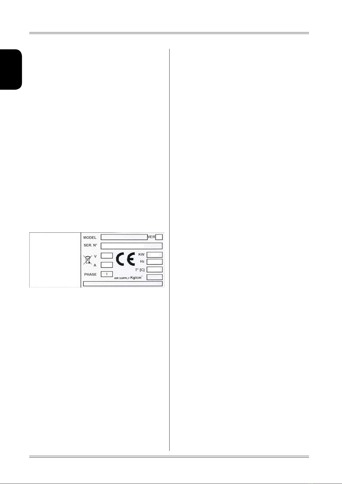
When exchanging information with the manufacturer
or the technical assistance staff authorised by the
former, quote the rating plate information and the
serial number of the machine.
This manual must be kept for the entire lifetime of
the machine, and if necessary (e.g.: damage making
all or some of it illegible, etc.) the user must request
another copy exclusively from the manufacturer,
quoting the publication code indicated on the cover.
1.4 MANUAL UPGRADES
This manual is an integral part of the machine and
reflects the state of the art at the moment it was
put on the market. The publication complies with the
directives in force on that date; the manual cannot
be considered inadequate as a result of regulatory
updates or modifications to the machine.
Any manual upgrades that the manufacturer may see
fit to send to users will become an integral part of
the manual and must be kept together with it.
Introduction

6
Ver. 04-2015
ENGLISH
Use and Maintenance Manual
Introduction
1.5 COLLABORATION WITH USERS
The manufacturer will be pleased to provide its cus-
tomerswithanyfurtherinformationtheymayrequire
andwillconsider proposalsfor improvingthis manual
in order to more fully satisfy the requirements it was
written for.
In case of transfer of ownership of the machine,
which must always be accompanied by the use and
maintenancemanual,theoriginalusermustinform
the manufacturer of the name and address of the
new user in order to allow it to send the new user
any communications and/or updates deemed to be
indispensable.
This publication is the property of the Manufac-
turer and may not be fully or partly reproduced
without prior written agreement.
1.6 MANUFACTURER
The machine identification data is indicated on the
plate mounted on the machine.
The plate below is shown for the sake of example.
1.7 MANUFACTURER’S RESPONSIBILITYAND
WARRANTY
In order to make use of the manufacturer’s warranty,
the user must scrupulously observe the precautions
contained in the manual, in particular he must:
▪never exceed the limits of use of the machine;
▪always constantly and carefully clean and service
the machine;
▪havethemachineusedbypeopleofprovencapacity
and attitude, adequately trained for the purpose.
The manufacturer declines all direct and indirect
liability caused by:
▪use of the machine in a different way from that
indicated in this manual
▪use of the machine by people who have not read
and fully understood the contents of this manual;
▪use in breach of specific regulations in force in
the country of installation;
▪modifications made to the machine, software
and operating logic, unless authorised by the
manufacturer in writing;
▪unauthorised repairs;
▪exceptional events.
Transfer of the machine to a third party must also
include this manual; failure to include the manual
automaticallyinvalidatesalltherightsofthepurchaser,
including the terms of warranty, where applicable.
If the machine is transferred to a third party in a
country with a different language from the one writ-
ten in this manual, the original user shall provide a
faithful translation of this manual in the language of
country in which the machine will operate.
1.7.1 Terms of warranty
The Manufacturer guarantees the machines it manu-
facturersagainstallmanufacturingorassemblyfaults
for 12 (twelve) months from the date of collection
or delivery.
The Manufacturer undertakes to replace or repair
any part which it deems to be faulty free of charge
at its factory, carriage paid.
If a Manufacturer’s repairman (or a person author-
ised by the same) is required to work at the user’s
facilities, the relative travel expenses and board and
lodging shall be charged to the user.
The free supply of parts under warranty is always
subject to the faulty part being inspected by the
manufacturer (or a person authorised by the same).
The warranty is not extended following repairs or
other work done to the machine.
The warranty does not cover damage to the machine
deriving from:
▪transport;
▪neglect;
▪improper use and/or use not in compliance with
the instructions in the operating manual
▪incorrect electrical connections.
The warranty is invalidated in case of:
▪repairs made by people who were not authorised
by the manufacturer;
▪modifications that were not authorised by the
manufacturer;
▪use of parts and/or equipment that were not
supplied or approved by the manufacturer;
▪removaloralterationofthemachineidentification
plate.

7
Ver. 04-2015
ENGLISH
Use and Maintenance Manual
1.8 TECHNICAL ASSISTANCE SERVICE
For any technical service operation, contact the
manufacturerdirectlyoranauthoriseddealeralways
quotingthe model,the versionandthe serialnumber
of the machine.
1.9 COPYRIGHT
The information contained in this manual may not
be disclosed to third parties. Partial or total dupli-
cation, unless authorised by the Manufacturer in
writing, through photocopying, duplication or other
systems, including electronic acquisition, is breach
of copyright and can lead to prosecution.
Introduction

4
2
3
1
8
Ver. 04-2015
ENGLISH
Use and Maintenance Manual
2. INSTALLATION
1. Unpack the machine and place the front guard
on the ground with the spindle locking/release
pedal,theZero Weight liftand theside guard(1).
3. Do not install the machine in an area directly
exposedtosunlightorwheretherearereflections
from the floor. The machine might malfunction
if there is excess light (3).
2. Absolutely do not force the side column when
unloading the machine from the pallet and be
careful with the electrical wiring (2).
Installation
4. Avoid positioning objects made of a particularly
reflecting material in the areas indicated in gray,
as they might interfere with laser reading (4).

5
6
7
8
9
10
9
Ver. 04-2015
ENGLISH
Use and Maintenance Manual
Installation
5. Hold up the lift using a wooden board (5)
6. Screw in the elbow union and fit all the wiring and
pneumatic connectors inside the lift (6)
7. Connect the 8 Ø tube (7)
8. Connect the 140 Ø tube (8)
9. Connect the lift pedal cable with a male/female
Faston (9)
10. Connect the footboard micro limit switch cable
with a male/female Faston (10)

8
11
12
13
14
10
Ver. 04-2015
ENGLISH
Use and Maintenance Manual
Installation
11. Connectthepneumaticlockingpedalmicroswitch
cable with a male/female Faston (11)
12. Position and fasten the front footboard (12)
13. Position the side guard and fasten it (13)
14. Position the lift with the footboard in line with
the spindle (14)

16
25Nm
15
17
17
16
11
Ver. 04-2015
Use and Maintenance Manual
ENGLISH
Installation
15. Drill the holes in the floor using a drill with an 8Ø bit and fit the expandable bolts provided as indicated
in the drawing and tighten them to a torque of 25 Nm. As indicated in the box, in the last phase, fasten
the mounting brackets on the side of the column and tighten to a torque of 25Nm (15) .
16. Check that the mains input voltage and frequency
parameters are compatible with the data shown
on the wheel balancing machine plate (±10%)
(16).
17. Check proper pneumatic connection; the machine
and the lift require at least 7 kg/cm² (~ 0.7 MPa;
~7 BAR; ~105 PSI) (17).
18. Turn on the machine and carry out
the following
operations:
▪ LASER CALIBRATION
▪TAPER CALIBRATION
▪MACHINE CALIBRATION

12
Ver. 04-2015
Use and Maintenance Manual
ENGLISH
Machine description
3.1 MACHINE FUNCTION
It is a wheel balancing machine for cars, light commercial vehicles and 4-WDs .The wheels must weigh less
than 75 kg. It can be operated in a temperature range of 0° to + 45° C.
It can operate only on a flat and non-resilient surface.
Do not mount any wheels other than motorcycle, car or truck wheels on the wheel balancing machine.
Thanks to the new and exclusive VDD (Virtual Direct Drive) system, reliable unbalance measurements can be
made in a short time, almost half the cycle time of other wheel balancing machines in this range.
3. MACHINE DESCRIPTION
The main features include:
▪Automatic dimension measurement
▪Inside and outside rim eccentricity measurement
▪Automatic minimisation of static unbalance
▪Wheel taper measurement
▪Selection of optimal wheel mounting
▪Customisable certificate printout
▪Machine setting menu
▪Unbalance optimisation
▪Static program, ALUS; SPLIT; BPC; indication of exact position of the correction weights; self-diagnostics;
self-calibration
▪Statistics of weights used
LASER POSITIONING
PNEUMATIC LOCKING PEDAL
RIM INTERIOR LED LIGHT
ZERO WEIGHT PEDAL ZERO WEIGHT (OPTION)
CONE HOLDER
EXTERNAL SCANNING LASER
PNEUMATIC SPINDLE
INTERNAL SCANNING LASER
GUARD
WEIGHT TRAY
TFT TOUCH SCREEN
ZERO WEIGHT CARRIAGE LEVER

Ø250mm
Zona d’azione laser scansione
13
Ver. 04-2015
ENGLISH
Use and Maintenance Manual
3.2 TECHNICAL SPECIFICATIONS
The following data refers to the wheel balancing
machine in its standard configuration.
Single phase power supply 115 /230 V 50/60 Hz
Protection class IP 54
Rated power 0,15 kW
Balancing speed 100 min-1
Cycle time per wheel
4.7 seconds (5 3/4"x14")
15 Kg
Measurement uncertainty 0.5 g.
Average noise < 70 dB(A)
Rim width setting range 1.5”-20” or 40 - 510 mm
Settable diameter 10” ÷ 30” or 265 ÷ 765 mm
Min/max. compressed air pressure 7 ÷ 10 Kg/cm2
~ 0.7 ÷ 1 Mpa;
~ 7 to 10 BAR;
~ 105 to 145 PSI.
Machine weight 220 kg.
3.3 DIMENSIONS
3.4 WARNINGS
CAUTION:
Keep The AreA INdICATed IN The fIgUre free Of TOOls,
AdApTers, eTC.
The function buttons are selected by pressing on the
TOUCH SCREEN.
CAUTION:
press The bUTTONs ONlY wITh YOUr fINgers.
Never Use The COUNTerweIghT grIppers Or OTher
pOINTed ObjeCTs !
Machine description
3.4.1 Periodic cleaning
CAUTION
The TOUCh pANel ANd The exTerNAl sCANNINg lAser effICIeNCY
CAN be gUArANTeed UsINg AsOfT ClOTh ANd NON-AbrAsIve
COmmerCIAl glAss/plAsTIC CleANINg sprAY Or eThANOl Or
NATUrAl deTergeNTs.
dO NOT Use:
OrgANIC sOlveNTs TYpe NITrO ThINNer
TUrpeNTINe
peTrOl
TrIChlOrOeThYleNe
ACeTONe
Scanning laser range
of action

SE2-MOUNTING
0mm
1-2mm
A B
CD
E F
G
Si raccomanda tassativamente la verica periodica (mensile) del corretto serraggio
del terminale SE2 (780N m 575Ft Ibs). Un serraggio errato può provocare imprecisioni
di equilibratura e danni alla macchina NON COPERTI DA GARANZIA.
We strongly recommend a periodic (monthly) testing of the proper tightening
of the SE2 terminal (780N m 575Ft Ibs). A bad tightening can cause balancing
inaccuracies and machine damages NOT COVERED BY WARRANTY.
Nous recommandons fortement la vérication périodique (mensuel) du correct serrage
du terminal SE2 (780N m 575Ft Ibs). Un mauvais serrage peut entraîner des imprécisions
d’équilibrage et dommages à la machine PAS COUVERTS PAR LA
GARANTIE.
Eine regelmäßige (monatliche) Kontrolle der richtigen Befestigung des Endstücks SE2 wird
unbedingt empfohlen. Eine falsche Befestigung kann zu einer ungenauen Auswuchtung
und zu Maschinenschäden führen, die NICHT VON DER GARANTIE GEDECKT SIND.
Es muy recomendable una prueba periódica (mensual) del correcto apriete del
terminal SE2 (780N m 575Ft Ibs). Un mal ajuste puede perjudicar la calidad del
equilibrado y causar daños a la máquina NO CUBIERTO POR LA GARANTÍA.
É altamente recomendável um teste periódico (mensal) o aperto adequado
do terminal SE2 (780N m 575Ft Ibs). Um mau aperto pode causar imprecisões
equilíbrio e danos à máquina NÃO COBERTOS PELA GARANTIA.
14
Ver. 04-2015
Use and Maintenance Manual
ENGLISH

SE2-DISMOUNTING
360°
Cone
A B
CD
E
Quando possibile, centrare le ruote con cono dall’interno (vedi disegno). Evitare di usare il manicotto RL con cerchi in ferro.
Whenever possible, centre the wheels with the cone from the inside (see the drawing ). Avoid using the RL sleeve with metal rims.
Lorsque c’est possible, centrer les roues avec le cône de l’intérieur (voir dessin). Eviter d’utiliser le manchon RL avec les jantes en fer.
Wenn möglich, die Räder mit Konus von Innen heraus zentrieren (siehe Zeichnung). Bei Eisenfelgen die Verwendung der Muffe RL vermeiden.
Siempre que sea posible, centrar las ruedas con cono desde dentro (véase dibujo). Evitar usar el manguito RL con llantas de hierro.
Quando possível, centre as rodas com cone pelo lado de dentro (ver gura). Evite utilizar a luva RL com jantes de ferro.
15
Ver. 04-2015
Use and Maintenance Manual
ENGLISH

16
Ver. 04-2015
Use and Maintenance Manual
ENGLISH
Wheel lifting
4. WHEEL LIFTING (OPTION)
▪Position the wheel on the carriage resting it against the ZERO WEIGHT carriage lever. Check that the
pneumatic spindle is enabled for mounting (open); if not, push the pneumatic locking pedal.
▪Push the Zero Weight pedal.
cAuTIoN:
NeveR push The ZeRo WeIGhT pedAl If TheRe Is ANyoNe sTANdING IN The RANGe of AcTIoN of The lIfT.
cAuTIoN:
befoRe pushING The pedAl To lIfT AWheel, AlWAys checK ThAT The spINdle Is opeN
(If NoT, The lIfT mIGhT NoT AsceNd oR AsceNd INcoRRecTly).
As soon as the wheel lifts off the ground, it is ready for mounting on the wheel balancing machine at zero
weight.
▪Position the central hole of the wheel at the height of the spindle and slide the wheel onto the spindle
with the aid of the Zero Weight carriage lever.
Zero Weight carriage lever
Pneumatic locking pedal Zero Weight pedal

18
Ver. 04-2015
Use and Maintenance Manual
ENGLISH
Use of the wheel balancing machine
6.1 DIMENSION ACQUISITION
6. USE OF THE WHEEL BALANCING MACHINE
Acquires the wheel dimensions
Enables/disables taper and tread
measurement
Return to main screen
Outside rim eccentricity measurement
(use with the rim only)
NEW WHEEL
Press the button to acquire the dimensions.
Close the guard to perform the balancing spin.
ATTeNZIoNe
befoRe pRessING The buTToN , posITIoN The Wheel IN such AWAy ThAT ANy WeIGhTs AlReAdy oN The RIm do NoT fAll WIThIN The
ReAdING AReA of The INTeRNAl lAseR, ThAT WAy excludING ANy dImeNsIoN meAsuRING INAccuRAcIes.
WHEEL THE SAME AS PREVIOUS
Close the guard to perform the balancing spin.
The machine in any case checks the wheel dimensions and if they are different from the previous wheel,
automatically measures them again. With this innovative system you can balance a set of 4-5 wheels meas-
uring the dimensions only once, thus saving a lot of time.
TAPER AND TREAD MEASUREMENT AT THREE POINTS
Press the button to enable/disable complete taper and tread measurement.
This function uses a special measuring cycle that extends the cycle time by a few seconds.
The setting remains stored even when the wheel balancing machine is turned off.
OUTSIDE RIM ECCENTRICITY MEASUREMENT WITHOUT TYRE
Press the button ( OUTSIDE RIM RUNOUT)
CANCEL DIMENSION SETTING
Press the button .

19
Ver. 04-2015
Use and Maintenance Manual
ENGLISH
Use of the wheel balancing machine
6.2 CORRECTION MODE SELECTION
Press from the unbalance measurement screen.
Press the weight symbol in the desired correction position.
If doing the unbalance correction in static mode only, press and hold the outside adhesive weight symbol
for once or twice (depending on the current correction mode).
Goes back to the unbalance measurement
screen, automatically recalculating the
unbalance values.

20
Ver. 04-2015
Use and Maintenance Manual
ENGLISH
Use of the wheel balancing machine
6.3 UNBALANCE UNIT OF MEASURE SELECTION
Press the button / from the unbalance measurement screen
Selects grams
Selects ounces
Allows selecting whether to view the unbalance values expressed in grams or ounces.
Table of contents