Hoffrichter CARAT II pro User manual

Quality makes the Difference
User’s manual
for patients
as of device software 1.000
CARAT II pro
Ventilator
Device type 9LV203
HOFFRICHTER GmbH
Mettenheimer Straße 12 / 14
19061 Schwerin
Germany
Telephone: +49 385 39925 - 0
Fax: +49 385 39925 - 25
Email: info@hoffrichter.de
www.hoffrichter.de
CARAT II pro Patient 1.000 ENG_2014-07-16_01 Article no.: 5000 0626
User’s manual CARAT II pro for patients

3
CARAT II pro
User's manual
for patients
©2014 HOFFRICHTER GmbH
All rights reserved.
The content published in this user's manual is the sole property of the HOFFRICHTER
GmbH. All forms of reproduction, editing, distribution and any kind of exploita-
tion, even in part, require the prior written consent of the HOFFRICHTER GmbH.
The HOFFRICHTER GmbH reserves the right to amend or replace this user's manual
without prior notice.
Please ensure that you are always working with the most current version of this
user's manual. Should you have any questions, please contact the ventilation
device provider, or check our information at www.hoffrichter.de.
The respiratory device may only be operated and maintained by trained personnel.
The following documents are available for CARAT II pro in addition to this user's
manual:
• User's manual for CARAT II pro for physicians and medical professionals
• Brief instructions for CARAT II pro
• Service manual
• Hygiene concept
• Maintenance plan

4
Please read fi rst this user's manual carefully and in its entirety before fi rst
using the ventilator.
In particular, follow all safety and cleaning instructions.
Keep the instructions in close proximity to the device for immediate re-
ference if necessary.
Every HOFFRICHTER GmbH device is supplied with a serial number for tracea-
bility purposes.
Please enter your device’s serial number here. You will fi nd the serial number on
the rating plate on the bottom of the device.
.............................................
Please always quote the serial number for all queries and complaints.
The device complies with the requirements of Directive 93/42/EEC.

Table of contents5
TABLE OF CONTENTS
CHAPTER 1 ............................................................................ 11
INTRODUCTION ...........................................................................................11
Scope of delivery ...........................................................................................12
Symbols ........................................................................................................14
Intended use ..................................................................................................19
Contraindications ...........................................................................................19
Side effects ....................................................................................................20
CHAPTER 2 ............................................................................ 21
SAFETY INFORMATION ...............................................................................21
General safety instructions .............................................................................22
Electrical safety ..............................................................................................24
Installation requirements and transport ...........................................................25
Instructions before commissioning .................................................................26
Using of oxygen .............................................................................................26
Safety-related test ..........................................................................................27
CHAPTER 3 ............................................................................ 29
DESCRIPTION OF DEVICE ..........................................................................29
Front side connecting points ..........................................................................30
Rear side connecting points ...........................................................................31
Control elements ............................................................................................33
LED displays ..................................................................................................35
Movable and removable housing parts ...........................................................37
CHAPTER 4 ............................................................................ 39
COMMISSIONING ........................................................................................39
Setting up the device .....................................................................................40
Power supply .................................................................................................40
Connecting the tube circuit ............................................................................47
Calibrating the tube circuit ..............................................................................52
Connecting the alarm box or the nurse call .....................................................54
SpO2 sensor connection ................................................................................55
Inserting the SD card .....................................................................................56
RemovING the SD card ..................................................................................56
Using oxygen .................................................................................................57

6Table of contents
Using the functional bag .................................................................................61
Switching the device on .................................................................................62
Switching the device off .................................................................................62
CHAPTER 5 ............................................................................ 63
VENTILATION MODES .................................................................................63
CHAPTER 6 ............................................................................ 65
DEVICE OPERATION ....................................................................................65
Key lock.........................................................................................................65
User profi les ...................................................................................................65
Menu structure ..............................................................................................66
Basic operation ..............................................................................................66
Basic screen layout ........................................................................................68
Explanation of toolbar icons ...........................................................................69
Enabling a screen ..........................................................................................71
Monitoring .....................................................................................................73
Activating a ventilation set ..............................................................................79
Display of stored alarms .................................................................................81
System settings .............................................................................................82
Statistics ........................................................................................................88
Starting ventilation .........................................................................................90
Stopping ventilation .......................................................................................90
CHAPTER 7 ............................................................................ 91
ALARMS AND MESSAGES ..........................................................................91
General information ........................................................................................92
Alarm sound test ............................................................................................92
Audible alarm output (audio alarms) ................................................................93
Visible alarm output .......................................................................................94
Alarm log .......................................................................................................96
Forwarding alarms .........................................................................................96
Alarm overview ..............................................................................................97
Messages ....................................................................................................101
CHAPTER 8 .......................................................................... 103
CLEANING AND DISINFECTION ................................................................103
Overview ......................................................................................................104
Cleaning the device ......................................................................................106

Table of contents7
Cleaning the tube circuit ...............................................................................106
Cleaning the mask .......................................................................................106
Cleaning the headgear .................................................................................107
Cleaning / Replacing the fi lter ........................................................................107
CHAPTER 9 .......................................................................... 109
ROUTINE CHECKS AND MAINTENANCE WORK ......................................109
Overview ......................................................................................................110
Battery maintenance ....................................................................................111
CHAPTER 10 ........................................................................ 113
APPENDIX ..................................................................................................113
Data management .......................................................................................114
Error messages ............................................................................................115
Technical data ..............................................................................................117
Replacement parts and accessories .............................................................121
Manufacturer's declaration on electromagnetic compatibility .........................128
Disposal.......................................................................................................129
Disclaimer ....................................................................................................130

8List of fi gures
LIST OF FIGURES
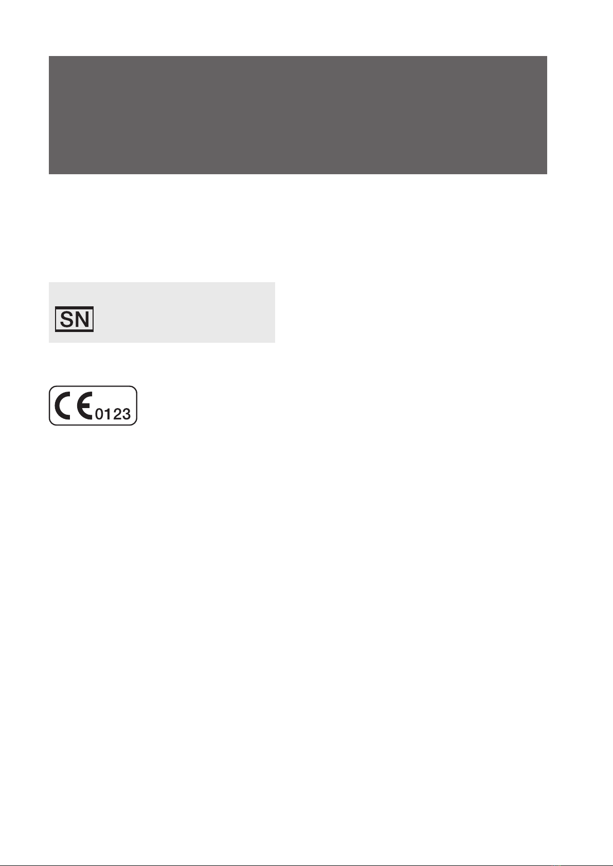
Figure 1: Rating plate ....................................................................................15
Figure 2: Connections at the front side of the device .....................................30
Figure 3: Connections at the rear side of the device ......................................31
Figure 4: Control elements ............................................................................33
Figure 5: LED displays ..................................................................................35
Figure 6: Left device side ..............................................................................37
Figure 7: Right device side ............................................................................37
Figure 8: Setting up the device .....................................................................40
Figure 9: Mains connection via power supply unit ..........................................41
Figure 10: Start screen ...................................................................................42
Figure 11: Standby screen ..............................................................................42
Figure 12: AKKUPACK uni BASE (right) / AKKUPACK uni PLUS (left) ...............45
Figure 13: Connecting AKKUPACK uni BASE ..................................................46
Figure 14: Connecting a single line patient circuit ............................................48
Figure 15: Connecting a double line patient circuit ..........................................49
Figure 16: Connecting the humidifi er - single line patient circuit .......................50
Figure 17: Connecting the humidifi er - double line patient circuit......................51
Figure 18: "Measurement without pressure tube" message box .......................52
Figure 19: Connecting alarm box ....................................................................54
Figure 20: Connecting the SpO2 sensor ..........................................................55
Figure 21: Inserting SD card ...........................................................................56
Figure 22: Removing SD card .........................................................................56
Figure 23: Connecting the oxygen source (rear of unit) ....................................57
Figure 24: Connecting the FiO2 sensor (single line patient circuit example) .......59
Figure 25: Functional Bag ...............................................................................61
Figure 26: Switching on the device .................................................................62
Figure 27: Switching off the device..................................................................62
Figure 28: Ventilation modes overview ...........................................................63
Figure 29: User profi le in the toolbar................................................................65
Figure 30: Basic screen layout ........................................................................68
Figure 31: Home screen .................................................................................71
Figure 32: Monitoring screen (data) .................................................................74
Figure 33: Monitoring screen (graphs) .............................................................75
Figure 34: Monitoring screen (freeze graphs) ...................................................76
Figure 35: Flow-Volume-Loop .........................................................................77
Figure 36: Volume-Pressure-Loop ...................................................................77
Figure 37: Flow-Volume-Loop .........................................................................78
Figure 38: Parameter screen ..........................................................................79
Figure 39: Alarm log screen ............................................................................81
Figure 40: System screen ...............................................................................84

List of fi gures9
Figure 41: Statistics screen (1 ventilation parameter) .......................................89
Figure 42: Stop ventilation ..............................................................................90
Figure 43: Alarm displays in the toolbar ...........................................................93
Figure 44: Alarm output in the toolbar .............................................................94
Figure 45: Alarm output in the textbox ............................................................95
Figure 46: Alarm box ......................................................................................96
Figure 47: Messages in the toolbar ...............................................................101
Figure 48: Filter cassette structure ................................................................107

10List of tables
LIST OF TABLES
Table 1: Operating time with battery power and factory default settings ........43
Table 2: Overview ventilation modes .............................................................64
Table 3: Adjustable alarms ............................................................................97
Table 4: Adjustable alarms ............................................................................98
Table 5: Fixed Alarms ...................................................................................99
Table 6: Fixed Alarms .................................................................................100
Table 7: Messages .....................................................................................101
Table 8: Cleaning intervals - overview .........................................................104
Table 9: Service intervals - overview ...........................................................110
Table 10: Data management .........................................................................114
Table 11: Error messages during operation and at device start-up ................115
Table 12: Error messages during operation and at device start-up ................116

Chapter 1: Introduction 11
CHAPTER 1
INTRODUCTION
This chapter contains general information on the use and operation of the ventilator.

12Chapter 1: Introduction
SCOPE OF DELIVERY
Illustration Name
CARAT II pro Ventilator
Switched-mode power supply
Mains cable
Disposable double line patient circuit for adults
with pressure measuring tube
(L = 180 cm, 22 mm)
Adapter for bacterial fi lter
SD card
Straight FiO2 connection adapter
Carrying case

Chapter 1: Introduction 13
Illustration Name
Spare fi lter cassette, complete (open) with fi lters
Spare coarse fi lter, 1 pack (2 ea)
Spare fi ne fi lter, 1 pack (5 ea)
User's manual for the patient
Brief instructions
Final inspection certifi cate

14Chapter 1: Introduction
SYMBOLS
PACKAGING SYMBOLS
Symbol Meaning
European Article Number
Article number
Serial number
CE - Declaration of Conformity
Transport and store package with arrows pointing up at all times
Fragile contents
Protect from moisture!
5
95
Humidity range during storage and transport
250 hPa
1100 hPa
Air pressure range during storage and transport
-20°C
+55°C
Temperature range for storage and transport up to 1 month
-20°C
+45°C
Temperature range for storage and transport up to 6 months
-20°C
+35°C
Temperature range for storage and transport longer than 6 months
HANDLE
WITH CARE
IF DAMAGED
KEEP
UPRIGHT
LITHIUM ION RECHARGEABLE
BATTERIES INSIDE
(No lithium metal)
Do not damage or mishandle this package. If package
is damaged, batteries must be quarantined, inspected
and repacked. For additional emergency information call:
+49 385 39925 - 0
ENTHÄLT WIEDERAUFLADBARE
LITHIUM-IONEN BATTERIEN
(Kein Lithium-Metall)
Vorsichtig behandeln! Bei Beschädigungen der Ver-
packung müssen die Batterien ausgesondert, überprüft
und neu verpackt werden! Informationen für den Notfall:
+49 385 39925 - 0
CAUTION
VORSICHT
IF DAMAGED
For more information, call +49 385 39925-0
Lithium-ion Batteries
DO NOT LOAD OR TRANSPORT
PACKAGE IF DAMAGED
CAUTION!
CAUTION! Device contains lithium-ion batteries

Chapter 1: Introduction 15
SYMBOLS ON THE RATING PLATE
The rating plate is on the back of the device
Figure 1:
SN
EAG1300001
IP22
CARAT II pro
Ventilator
Type: 9LV203
Quality makes the Difference
Li-Ion ICR 18650
14.8V; 4400mAh; 65.12Wh
DC-INPUT O
2
-INPUT
24V
12V
max. 5A max. 15l/min
1000 hPamax. 10A
Rating plate
Symbol Meaning
Observe the warning and safety instructions in the user’s manual.
Protection class II (protective insulation)
BF application part
IP22 Protect against:
• solid foreign objects with diameters from 12.5 mm
• access to hazardous parts with a fi nger
• falling / dripping water, as long as the housing is tilted
up to15°
Serial number
CE - Declaration of Conformity
Manufacturer
Do not dispose of the device with the household waste. Please contact
the relevant customer services department to fi nd out how to properly
dispose of the device.

16Chapter 1: Introduction
SYMBOLS ON THE DEVICE
Symbol Meaning
Connecting points
Inspiration tube connection
Expiration tube connection
Control tube connection
Pressure measuring tube connection
FiO2 sensor connection
DC DC connection
SpO2SpO2 sensor connection
Com Com-interface
Remote alarm/nurse call connection
USB interface
O2FiO2 connection
O2FiO2 output
SD card slot

Chapter 1: Introduction 17
Symbol Meaning
Operation
Alarm key
ON/OFF key
Safe key
Home key
Escape key
LEDs
Alarm LED
Mains LED
Battery LED

18Chapter 1: Introduction
SYMBOLS USED IN THIS USER’S MANUAL
Important information is denoted by symbols in this user’s manual. Please ensure
that you follow these instructions in order to avoid accidents, personal injury and
material damage.
In addition, the local accident prevention regulations and general safety regula-
tions in force in the area of use must be observed.
This symbol denotes general safety instructions. Follow these instructions
to avoid accidents, personal injury or material damage.
This symbol denotes hazardous situations that lead to serious injuries or death.
This symbol denotes hazardous situations that may lead to serious injuries
or death.
This symbol denotes hazardous situations that may lead to light or severe
injuries.
This symbol denotes situations that may lead to material damage or dam-
age to the device.
This symbol denotes information, tips and instructions for the effi cient, cor-
rect use of the device.

Chapter 1: Introduction 19
INTENDED USE
The use of the device contrary to its intended use can endanger the health
of the patient.
CARAT II pro is used for continuous or intermittent respiratory support and for the
ventilation of patients. The device is suitable for adults and children from a tidal volume
of 50 ml and higher and is designed for home or clinical applications.
CARAT II pro has both pressure- and volume-controlled ventilation modes. The ven-
tilation can be invasive (e.g using a tracheostoma) or non-invasive (using a mask).
CARAT II pro has the technical prerequisites to allow it to run with a single line
patient circuit with exhalation valve or with a double line patient circuit as required.
The device can be connected to a low-pressure source of oxygen for ventilation
with increased oxygen concentration. There is also the option to combine CARAT II
pro with an external humidifi er.
CONTRAINDICATIONS
Ventilation may be contraindicated for certain pre-existing conditions.
The following conditions may be a contraindication for non-invasive ventilation:
• Severe cardiac arrhythmia
• Severe hypotension
• Severe epistaxis
• Pneumothorax or pneumomediastinum
• Pneumoencephalus
• Cranial trauma
• Status after cranial or brain surgery
• Acute infl ammation of the paranasal sinuses, middle ear infection or a perfo-
rated ear drum
• Aspiration hazard
In individual cases, the attending physician must decide on the therapy.

20Chapter 1: Introduction
SIDE EFFECTS
The following undesired side effects may occur in connection with artifi cial respiration:
Invasive ventilation:
• Complications due to tube / tracheal cannula
Mask ventilation:
• Pressure points and skin defects in the face
• Eye irritation due to leaks
• Gastric infl ation
• Aspiration
• Sinusitis
• Nose bleeds
General complications of mechanical ventilation:
• Pulmonary barotrauma / volutrauma caused by ventilation
• Ventilator-associated pneumonia
• Effects on the cardio-vascular system

Chapter 2: Safety warnings21
CHAPTER 2
SAFETY INFORMATION
This chapter contains safety instructions on the following topics:
• General safety instructions
• Electrical safety
• Installation and transport
• Commissioning
• Use of oxygen
• Safety-related test
Other manuals for CARAT II pro
1
Table of contents
Other Hoffrichter Medical Equipment manuals

Hoffrichter
Hoffrichter VECTOR et Reference guide

Hoffrichter
Hoffrichter TREND III CPAP User manual

Hoffrichter
Hoffrichter VECTOR et Cpap User manual

Hoffrichter
Hoffrichter Nasal Pillow 4in1 Mask User manual

Hoffrichter
Hoffrichter Point Reference guide

Hoffrichter
Hoffrichter TREND II User manual

Hoffrichter
Hoffrichter TREND III Reference guide

Hoffrichter
Hoffrichter TRENDvent Reference guide

Hoffrichter
Hoffrichter CARAT II pro User manual

Hoffrichter
Hoffrichter TREND III CPAP User manual