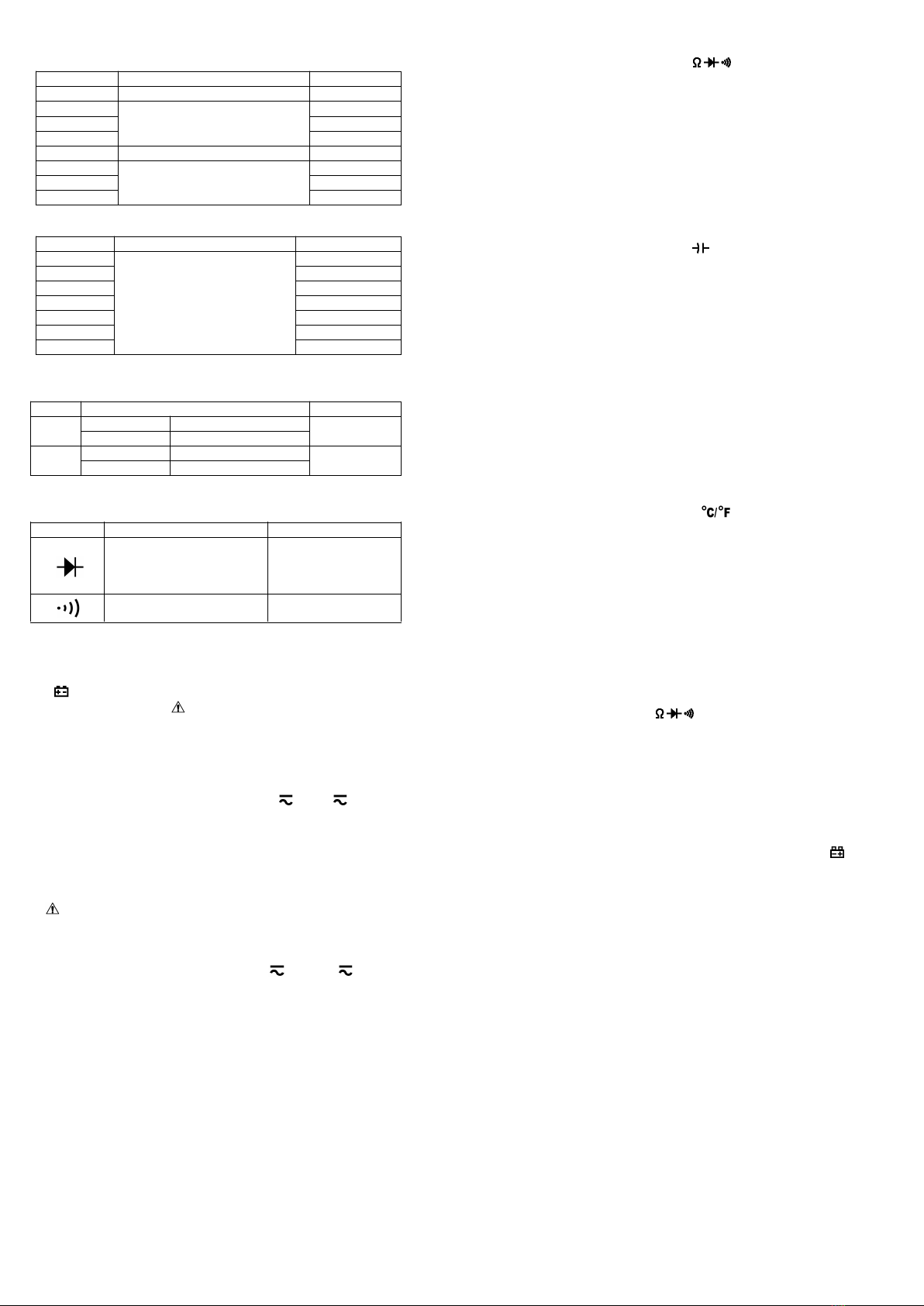
Range Accuracy Resolution
9.999nF ±(3.0% of rdg + 10 digits) 1pF
±(2.5% of rdg + 5 digits)
99.99µF ±(5.0% of rdg + 10 digits) 10nF
±(10.0% of rdg + 20 digits)
-- Overload protection: 250V DC or AC rms
Range Accuracy Resolution
± (0.1% of rdg + 5 digits)
-- Sensitivity: sine wave 0.6V rms (9.999MHz: 1.5V rms)
-- Overload protection: 250V DC or AC rms
Range Accuracy Resolution
150~1000℃± ( 3% of rdg + 2digits )
302~1832℉± ( 3% of rdg + 3digits )
-- NiCr-NiSi K-type sensor
-- Overload protection: 600mA/250V PPTC Resettable Fuse
6-9 Diode and Audible continuity test
Range Description Test Condition
Display read approximately
Built-in buzzer sounds if
resistance is less than 50Ω
Overload protection: 250V DC or AC rms
7. OPERATING INSTRUCTIONS
7-1 Attention before operation
7-1-1 Check battery. When the battery voltage drop below proper operation range,
the “ ” symbol will appear on the LCD display and the battery need to changed.
7-1-2 Pay attention to the “ ” besides the input jack which shows that the input
voltage or current should be within the specified value.
7-1-3 The range switch should be positioned to desired range for measurement
7-2 Measuring DC & AC Voltage
7-2-1 Connect the black test lead to COM/T- jack and the red to VΩHz jack.
7-2-2 Set the rotary switch at the desired “mV ” or “V” range position, it
shows symbol for testing DC voltage, if you want to test AC voltage, push “SEL”
7-2-3 Connect test leads across the source or load under measurement.
7-2-4 You can get reading from LCD. The polarity of the red lead connection will
be indicated along with the DC voltage value.
1.“ ” means you can’t input the voltage more than 600V, it’s possible to show
higher voltage, but it may destroy the inner circuit or pose a shock.
2. Be cautious against shock when measuring high Voltage.
7-3 Measuring DC & AC Current
7-3-1 Set the rotary switch at the desired “60A ” or “600A ” range position, it
shows symbol for testing DC current, if you want to test AC current, push “SEL”
7-3-2 Zero the reading by pressing “REL/INR” key for a reading of zero on the
7-3-3 Disconnect the test leads from the Meter.
7-3-4 Clamp the Jaws around the one conductor to be measured. Center the
conductor within the Jaw using the Centering Marks as guides.
7-3-5 You can get reading from LCD. The arrow in the Jaw indicates the direction
of positive current flow (positive to negative).
7-3-6 On AC current range, Press the “REL/INR” key for more than 2 seconds to
measure inrush current, and the “INR” sign will appear on the display, press it can
measure inrush current repeatedly, press it over 2 seconds to exit.
1. When the value scale to be measured is unknown beforehand, set the range
selector at the highest position.
2. When only “OL” is displayed, it indicates over-range situation and the higher
range has to be selected.
7-4-1 Connect the black test lead to COM/T- jack and the red to VΩHz jack.
7-4-2 Set the rotary switch at the desired “ ” range position.
7-4-3 Connect test leads across the resistance under measurement.
7-4-4 You can get reading from LCD.
NOTE: Max. input overload: 250V rms<10sec
1. For measuring resistance above 1MΩ, the mete may take a few seconds to get
2. When the input is not connected, i.e. at open circuit, the figure ‘OL’ will be
displayed for the over-range condition.
3. When checking in-circuit resistance, be sure the circuit under test has all
power removed and that all capacitors have been discharged fully.
7-5 Measuring Capacitance
7-5-1 Connect the black test lead to COM/T- jack and the red to VΩHz jack.
7-5-2 Set the rotary switch at the desired “ ” range position.
7-5-3 Connect test leads across the capacitance under measurement.
7-5-4 You can get reading from LCD.
NOTE: Max. input overload: 250V rms<10sec
1. Capacitors should be discharged before being tested.
2. When testing large capacitance, it will take longer time before the final
indication (For 100uF~99.99mF range, it will take about 10 seconds).
3. When testing small capacitance (≤1uF), to assure the measurement accuracy,
first press "REL/INR", then go on measuring.
7-6-1 Connect the black test lead to COM/T- jack and the red to VΩHz jack.
7-6-2 Set the rotary switch at the desired “Hz” range position.
7-6-3 Connect the probe across the source or load under measurement.
7-6-4 You can get reading from LCD.
7-7 Measuring Temperature
7-7-1 Connect the black banana plug of the sensor to COM/T- jack and the red
banana plug to the T+ jack.
7-7-2 Set the rotary switch at the desired “ ” range position, push “SEL” to
7-7-3 Put the sensor probe into the temperature field under measurement.
7-7-4 You can get reading from LCD.
1. The accessory of the meter WRNM-010 type contact thermocouple limit
temperature is 250 ℃(300 ℃shortly), please use special probe for test higher
2. Please don't change the thermocouple at will, otherwise we can't guarantee to
3. Please don’t importing the voltage in the temperature function.
7-8 Diode & Audible continuity Testing
7-8-1 Connect the black test lead to COM/T- jack and the red to VΩHz jack.
7-8-2 Set the rotary switch at the “ ” range position, push “SEL” to choose
Diode or Audible continuity measurement.
7-8-3 On diode range, connect the test leads across the diode under
measurement, display shows the approx. forward voltage of this diode.
7-8-4 On Audible continuity range, connect the test leads to two point of circuit,
if the resistance is lower than approx. 50Ω, the buzzer sounds.
NOTE: Make sure the power is cut off and all capacitors need to be discharged
8-1 When the battery voltage drop below proper operation range the " " symbol
will appear on the LCD display and the battery need to changed.
8-2 Before changing the battery, set the selector switch to “OFF” position and
remove the test leads from the terminals. Open the cover of the battery cabinet
8-3 Replace the old battery with the same type battery (AAA R03P 1.5V×3).
8-4 Close the cover of the battery cabinet and fasten the screw.
9-1 You must replace the test leads if the lead is exposed, and should adopt the
leads with the same specifications as origin.
9-2 Do not use the meter before the back cover is properly closed and screw
secured. Upon any abnormality, stop operation immediately and send the meter
9-3 When take current measurement, keep the cable at the center of the clamp
will get more accurate test result.
9-4 Repairs or servicing not covered in this manual should only by qualified
9-5 Periodically wipe the case with a dry cloth and detergent. Do not use
abrasives or solvents on this instruments.
9-6 Please take out the battery when not using for a long time.
[1] Test Leads: electric rating 1000V 10A
[2] “K” type thermocouple sensor probe
Above picture and content just for your reference. Please be subject to the
actual products if anything different or updated. Please pardon for not


