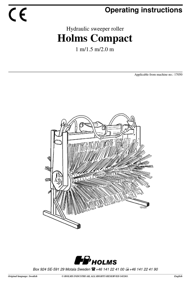
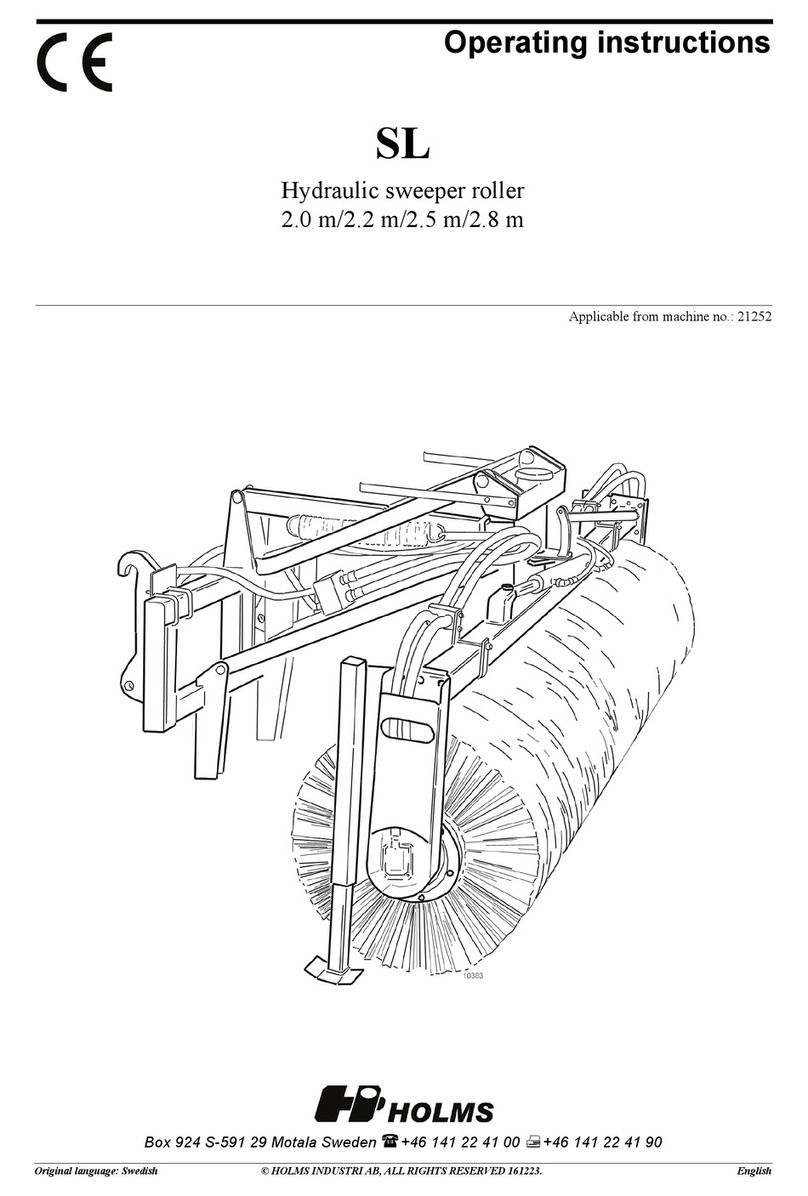
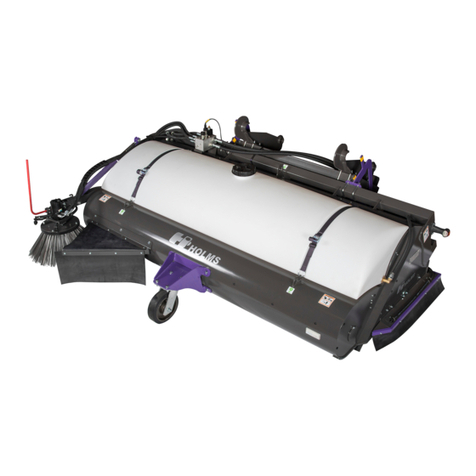
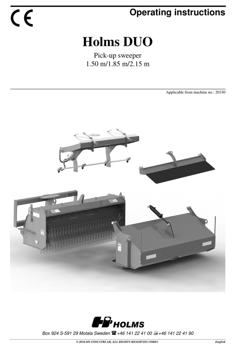
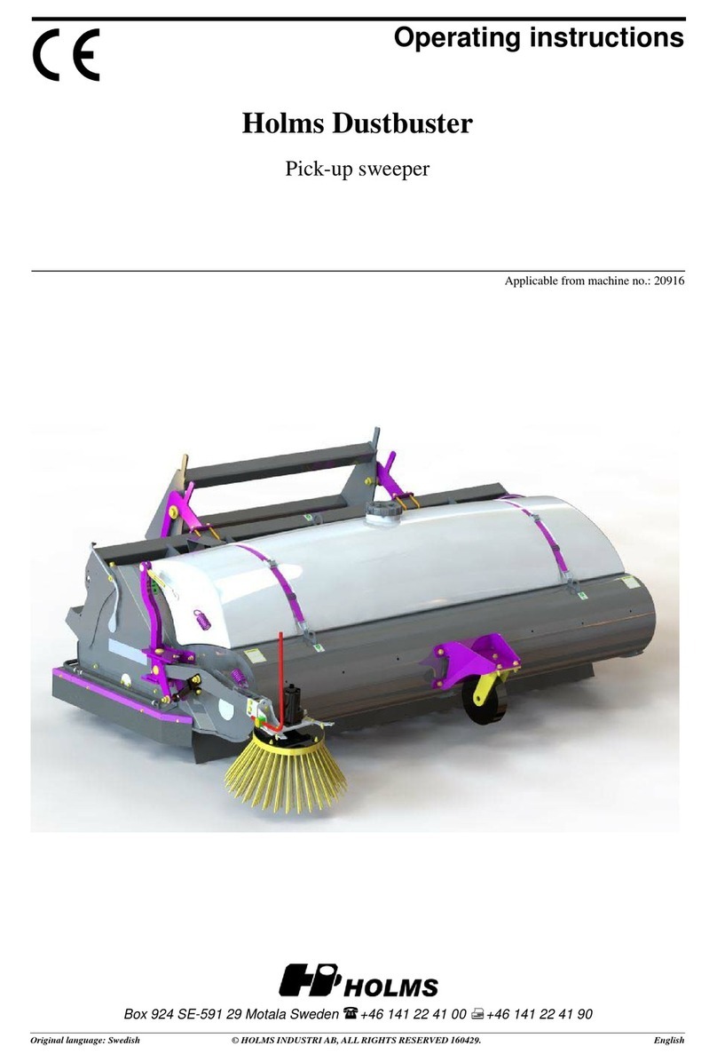
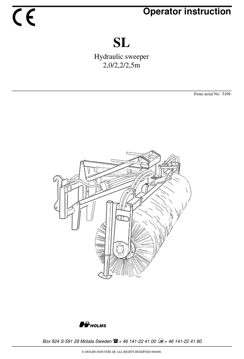
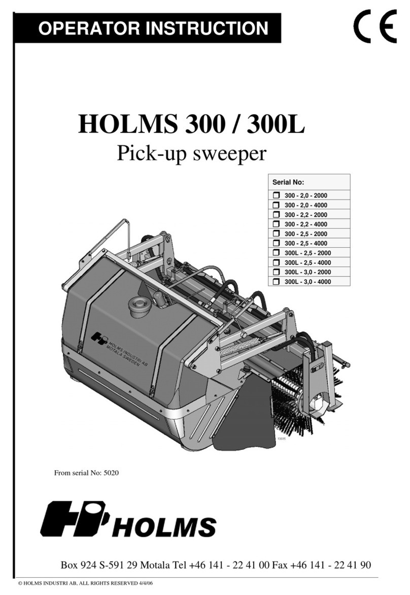
HOLMS SH Specifications

© HOLMS INDUSTRI AB, ALL RIGHTS RESERVED 060406.
Operator instruction
Box 924 S-591 29 Motala Sweden + 46 141-22 41 00 ¬+ 46 141-22 41 90
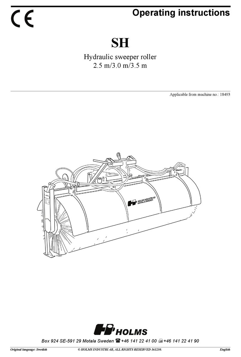
Hydraulic sweeper
2,5/3,0/3,5m
From serial No: 6261.
SH

SH
© HOLMS INDUSTRI AB, ALL RIGHTS RESERVED 060406. 2
Content
Foreword..................................................................... 3
Product facts............................................................... 4
General information ....................................................5
Extra equipment.......................................................... 5
Operator instruction .................................................6-8
Connecting to carrier with standard bracket......................6
Connecting to carrier without its own lift............................6
Sweeper setting height and tilt..........................................7
Setting of ground pressure................................................7
Sweeping........................................................................7-8
Disconnecting from carrier with standard bracket.............8
Disconnecting from carrier without its own lift ...................8
Maintenance ...............................................................9
After running .....................................................................9
Lubrication.........................................................................9
Change of brushes.................................................9-10
Dismounting of sweeper....................................................9
Change of brushes.......................................................9-10
Mounting of sweeper roll.................................................10

SH
3© HOLMS INDUSTRI AB, ALL RIGHTS RESERVED 060406.
PLEASE NOTE! READ THIS MANUAL CAREFULLY BEFORE USING
THIS EQUIPMENT FOR THE FIRST TIME.
Foreword
This instruction manual isintended as a guide to thecorrectoperationand maintenance of theequipment.Study
it carefully before using or before carrying out preventive maintenance on the equipment.
Much time and thought has gone into making this equipment as effective andsafe as possible. That effortcould
be wasted if you do not read, understand and follow these directions. Familiarize yourself with the equipment
and all the instructions. Keep the manual close at hand when using the equipment.
Note: This manual is designed for use in all our market areas. Subsequently, it includes special equipment for
particular areas. Ignore the instructions which do not apply to your equipment.
We continuously strive to improve our products and therefore reserve the right to make changes to them
whenever we feel it beneficial, without the obligation to alter equipment that has already been delivered and is
operational. We also reserve the right to change, without warning, information and equipment, as well as
instructions for maintenance and other service procedures.
It is the operator's responsibility to:
• Ensure that the implement is not used or handled in an incorrect manner.
• Ensure that any warning signs on the machine are readable.
• Ensure that no unauthorised person uses the machine, or is in close proximity of it during operation or when
maintenance work is being carried out.
• Ensure that the carrier is in the correct condition for operation (hydraulics, stability etc.).
When ordering spare parts, or during any other contact with Holms or your local dealer, always give the
machine's type and serial number (located on the machine identification plate).
When ordering gaskets for the hydraulic drives give the drive unit serial number (on the engine gable).
WE SPECIFICALLY DO NOT ADVISE MAKING ANY MODIFICATIONS, CHANGES
AND CONVERSIONS THAT HAVE NOT BEEN SANCTIONED BY HOLMS.
WE ALSO WARN AGAINST USING SPARE PARTS THAT HAVE NOT BEEN AP-
PROVED BY HOLMS.
DAMAGE OR FAULTS THAT MAY HAVE BEEN CAUSED BY NON-APPROVED
SPARE PARTS OR NON-APPROVED MODIFICATIONS ARE NOT COVERED BY
HOLMS' LIMITED GUARANTEE - SEE CURRENT GUARANTEE TERMS. HOLMS
WILL ALSO NOT COMPENSATE FOR ANY INJURIES TO PERSONS OR PROPER-
TY THAT MAY HAVE BEEN CAUSED BY NON-APPROVED SPARE PARTS OR
MODIFICATIONS.
Please pay particular attention to the warning symbols.

SH
© HOLMS INDUSTRI AB, ALL RIGHTS RESERVED 060406. 4
Model SH 2,5 SH 3,0 SH 3,5
Working width (m) 2,5 3,0 3,5
Max width (m) 2,7 3,2 3,7
Max height (m) 1,52 1,52 1,52
Working width at 30° angling (m) 2,2 2,6 3,0
Weight with std. brushes (kg) 470 500 530
Added weight with compl. sprinkling system, empty tank (kg) 200 200 200
Centre of gravity, A in sketch (mm) 1110 1120 1130
Centre of gravity, B in sketch (mm) 300 300 300
Centre of gravity, A in sketch incl. sprinkling system
empty (mm) 1100 1110 1120
Centre of gravity, B in sketch incl. sprinkling system
empty (mm) 220 220 220
Centre of gravity, A in sketch incl. sprinkling system filled (mm) 760 770 780
Centre of gravity, A in sketch incl. sprinkling system filled (mm) 220 220 220
Max oil flow (l/min) 210 210 210
1. Centre of gravity
*) All measures and weights are excl. hooks.
A
B

SH
5© HOLMS INDUSTRI AB, ALL RIGHTS RESERVED 060406.
Generally about the sweeper
The Sweeper SH standard design is adapted to front mounting
on wheel loaders. Attachment brackets are also available for
other applications such as trucks and agriculture tractors.
SH operates with two directacting hydraulic motors designed
for an oil flow of 70-200 l/min.
The suspension of the Sweeper gives a constant and evenly ap-
plied pressure against the ground. This gives minimal brush
wear and insensitiveness to unevenness, grooves, kerb stones
etc.
The Sweeper can be equipped with hydraulic and mechanical
angling ±30°.
Extra equipment
• Brush-cover in Polyethylene (plastic).
• Spraying system complete with 600 l tank, pump
and spraying ramp.
• El. hydraulic angling, makes it possible to angle during
sweeping, the carrier needs only one hydraulic function.
• Side shift, gives the possibility to move the sweeper
hydraulically ± 0,7 m.
• Truck attachment with built-in lifting function for VV-85,
DIN-plate or similar brackets.
• Different types of brushes, conventional or tufted, steel or
polypropylene (plastic).
2. Watertank 600 litre.
Distribution block
El. selector valve
3. El. hydraulic bevelling

SH
© HOLMS INDUSTRI AB, ALL RIGHTS RESERVED 060406. 6
Operating instruction
Connecting to carrier with standard bracket
1. Connect the sweeper to the loader attachment bracket. See the
respective carrier's instruction manual.
2. Connect the driving hose quick couplings to the 3:rd
hydraulic function outlet or to the carriers hydraulic motor
outlet.
3. Connect the angling cylinder quick coupling to the 4:th
hydraulic function outlet. In case the sweeper isequipped with
electric operated selector valve - connect the cable to the car-
rier. Electric circuit, see page 25 alt 33.
4. Start the sweeper by moving the operation control for the
3:rd function to its locking position or activate the hydraulic
motor circuit.
5. Check the sweeper rotation direction. If the sweeper rotates
in the opposite direction in closed position, shift closed posi-
tion of the lever or loosen the control lever and shift the quick
couplings for the 3:rd hydraulic function.
Connecting to carrier without its own lift
1. Connect the lift cylinder's two tubes to a double-acting hydraulic
function. Set the coupling's pin in position; see picture 4.
2. Lift up the bracket and drive the vehicle toward the sweeper. Attach
the sweeper to the carrier.
3. Lift the sweeper and remove the pin in the coupling. Take away the
supports.
4. Control the tilt angle; it is correct when the centre bracket on the
sweeper is vertical. (Preferably check with a level.) The tilt angle is
adjusted with spacers between the gate and lower bracket; see picture
5.
5. Connect the drive tubes' quick couplings to a double-acting hydrau-
lic outlet, or to the hydraulic motor circuit on the carrier.
6. Connect the angling cylinder's quick couplings to a double-acting
hydraulic outlet. (Or, if the sweeper is equipped with electrical hydrau-
lic angling, connect the cabling to the carrier.)
7. Start the sweeper by activating the hydraulic motor circuit.
8. Check that the sweeper rotates in the correct direction. If it rotates
wrongly in closed position, shift closed position of the lever or shift the
quick couplings for the hydraulic motor function.
4. Pin in the connecting position
5. Spacer between gate and bracket

SH
7© HOLMS INDUSTRI AB, ALL RIGHTS RESERVED 060406.
Sweeper setting, height and tilt
1. Lift up the sweeper and put the parking supports in
operating position (dia.6).
2. Start the sweeper with the 3:rd hydraulic function or with
the hydraulic motor circuit.
3. Slowly lower the sweeper until the height indicator yellow
markers are in line (dia. 7).
4. Tilt the sweeper until the tilting indicator markers are in line
(dia. 8).
5. Eventual readjustment of height as described in point 3.
Setting of ground pressure
The sweeper’s ground pressure can be adjusted for different
requirements. Set the machine in parking position, then use the
adjusting grip (dia. 9) to set the ground pressure.
Warning! Lower the unit, unloading the
suspension, before making any adjustments.
Attention! When banking a sweeper roller using electrohy-
draulic banking, the roller must be in contact with the ground.
Attention! Do not use the carrier lifting or tilting function for
ground pressure setting.
Warning! Always completely stop the unit
before making any adjustments.
1. Set the sweeper height and tilt.
2. Let the sweeper rotate a short while against the ground.
3. Measure the clean-swept stripe, it shall normally be about
15-25 cm.
Decrease the ground pressure by lowering the adjusting grip.
Increase the ground pressure by raising the grip (dia. 9).
Sweeping
By sweeping the setting normally shall be as described in
“Sweeper setting, height and tilt”. The yellow markers on the
height- and tilting indicators shall be in line. In this position
the loader bracket is vertical to the ground. The sweeper oper-
ates with even pressure over its whole width (dia.10).
Attention!Do not use the loader height and tilting function for
ground pressure adjustment.
6. Parking support in operating position
7. Height indicator
8. Tilt indicator
9. Adjusting grip

SH
© HOLMS INDUSTRI AB, ALL RIGHTS RESERVED 060406. 8
If greater pressure is required on one side or if it is necessary
to compensate for uneven brush wear the tilt angle can be ad-
justed.
By tilting the unit backwards more pressure is applied to the
side of the brush nearest the carrier (dia. 11).
By tilting the unit forwards more pressure is applied to the side
of the brush furthest from the carrier (dia. 12).
Lifting the unit from the ground, e.g. for transportation, is
most easily and quickly done by tilting it backwards.
Disconnecting from carrier with standard
bracket
1. Loosen the attachment bracket faucets before the sweeper
is placed on the ground to avoid damage on the suspension
system.
2. Lower and secure the support in parking position.
Attention! The sweeper brushes can be deformed if the sup-
ports are not used when sweeper is parked.
3. Put down the sweeper on the ground.
4. Loosen the quick couplings for the 3:rd and 4:th hydraulic
functions alternatively hydraulic motor circuit and the cable.
Disconnecting from carrier without its own lift
Attention! Before disconnecting the broom must be standing
straight with the angling cylinder and side shift. Otherwise the
sweeper may collide with the attachment.
1. Place the supports in parking position; see picture 13. Set
the coupling's pin in the lift position.
Attention! The brushes become deformed if the supports are
not used when the sweeper is parked.
2. Set the sweeper carefully down on the ground, release the
sweeper from the carrier, and reverse a little.
3. Lower the sweeper's gate to the lowest position with the lift
cylinder.
Warning!
Make sure the system has no pressure
before loosening the quick couplings.
4. Loosen the quick couplings and any electrical cabling.
10. Sweeper with even ground pressure
12. Sweeper tilted forwards
11. Sweeper tilted backwards
13. Supports in parking position

SH
9© HOLMS INDUSTRI AB, ALL RIGHTS RESERVED 060406.
Maintenance
After running
• Wash the sweeper, which increases the life-time and makes
it easier to detect eventual leakage or other defects.
• Inspect the sweeper concerning damages on hoses, brush
protectors, leaf spring or framework. Also check eventual
oil leakage.
Lubrication
A couple of times a year, the bar tube bearing shall be greased.
Clean the nipple and fill in until the grease pierces (dia 14).
Change of brushes
Place the supports in driving position and lower the machine
until the broom rests against the ground.
Dismounting of sweeper roll
1. Loosen the hydraulic hose brackets on the bar tube (dia 15).
2. Remove the four bolts from the gable side (dia 16).
3. Avoid the bare tube to spring up by holding a foot on the
plate of the support stand, then carefully remove the gable (dia
17).
Attention! Risk for clamping.
4. Angle thesweeper rollfrom the bar tube and pull the roll out
from the carrier housing on the other gable side.
Change of brushes
1. Loosen the screws and take away the sweeper roll end ring
(dia 18).
2. Put shackels in the two holes for the brush core mounting-
screws and put a lifting wire loop through the shackles.
3. Lift the sweeper roll in vertical position by using a traverse
crane or similar equipment.
4. Lift up the roll from the floor and pull down the brush
sections and the distance rings. Lower the sweeper roll.
14. Bar tube bearing
15. Bracket - hydraulic hoses
16. Removing the bolts
17. Removing the gable side

SH
© HOLMS INDUSTRI AB, ALL RIGHTS RESERVED 060406. 10
5. Check the core free from damage.
6. Fasten one end ring with screws on the core (dia 19).
7. Lift up the sweeper core with the end ring downwards.
8. Place one distance ring with the brush element pins into the
grooves of the brush core.
9. Place one distance ring.
10. Place one brush element turned, as in dia.20, and then an-
other distance ring.
11. Place alternating brush elements and distance rings. Please
notice that the brush rings shall be turned alternatively, so the
result will be as in dia 21. (When using Bee-line brushes).
12. To get the whole core "dressed" a thinner distance ring
alt. double brushes without distance ring is necessary at
the end in order to receive agreement of length.
13. Fasten the other end ring with screws.
Mounting of sweeper roll
1. Put the sweeper roll on the fixed gable side carrier housing.
2. Put the gable side with the hydraulic motor and carrier
housing on the two guide pins (dia 17).
Attention! Risk for clamping.
3. Mount the four gable side bolts (dia 16).
4. Mount the hydraulic hose bracket on the bar tube (dia 15).
Water sprinkling system (extra equipment)
• The pump must not be run for long periods when dry, i.e.
once the water has been used up the pump must be switched
off.
• The machine is equipped with water filters to prevent dirt
from getting into the system. The filters are located in the
tank's filling hole and can be rinsed clean and reused. The fil-
ters mustbe in position when the tank is filled, otherwise there
is a risk of the pump and water system being damaged.
• When there is a risk of freezing, empty the water from the
water tank, water pump and attendant hoses. The easiest thing
is to empty the tank first and then run the pump dry for 20-30
seconds. When emptying the tank, remove the hose coupling
from the tank.
19. End ring mounting
18. End ring screws
20. Mounting of brush element
21. Correct mounting
Brush element
Distance ring
This manual suits for next models
3
Table of contents
Other HOLMS Blower manuals