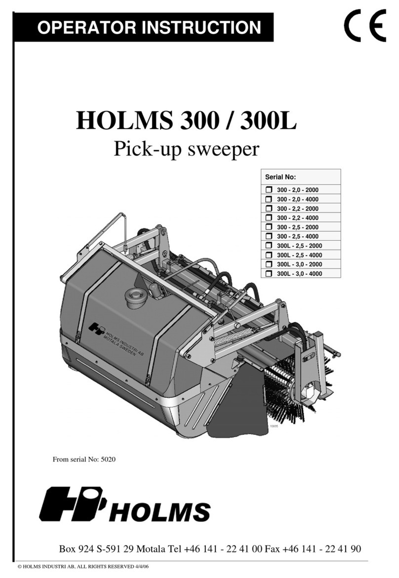
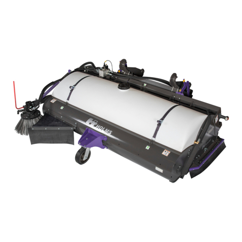
HOLMS 300 User manual

Original language: Swedish © HOLMS INDUSTRI AB, ALL RIGHTS RESERVED 141204. English
Operating instructions
Box 924 SE-591 29 Motala Sweden +46 141 22 41 00 ¬+46 141 22 41 90
Applicable from machine no.: 18479
Pick-up sweeper
2.0/2.2/2.5/3.0 m
HOLMS 300
Series no:
300 - 2.0 - 2000
300 - 2.2 - 2000
300 - 2.5 - 2000
300 - 2.5 - 4000
300 - 3.0 - 4000


HOLMS 300
© HOLMS INDUSTRI AB, ALL RIGHTS RESERVED 141204. 3
Warning labels..............................................................4
Safety...........................................................................7
Transport and storage..................................................9
Product data...............................................................10
Product Description....................................................11
Standard model.................................................11
Operating instructions ................................................12
Connection to carrier.........................................12
Operator settings ..............................................12
Emptying the refuse container ..........................14
Disconnection from carrier................................14
Connection of side brush (extra equipment).....14
Sprinkler............................................................14
Operating with side brush (extra equipment)....15
Service and maintenance...........................................17
After operation ..................................................17
Replacement of brush.......................................17
Replacement of brush on side brush
(extra equipment)..............................................20
Replacement of the Swish brush................................21
Tip.....................................................................21
Index...........................................................................22
Contents

HOLMS 300
4© HOLMS INDUSTRI AB, ALL RIGHTS RESERVED 141204.
Warning labels
There are several specific warning labels on this product; see the descriptions below. Make sure that
you understand the implications of these labels before using the product.
Clean/replace warning labels if they are illegible or are missing. Contact you Holms dealer if you
require new labels.
Risk of crushing - mind your hands and do not come too close to the machine (warning label
1530052)
Do not enter this area whilst the machine is in
operation. Mind your hands and keep them away
from this area whilst the tool is in use.
Keep a safe distance away from the machine
whilst it is in operation. Not following this rule
may lead to serious personal injury or, in a worst
case scenario, death.
Risk of crushing - do not come too close to the machine (warning label 1530053)
Keep a safe distance away from the machine
whilst it is in operation. Not following this rule
may lead to serious personal injury or, in a worst
case scenario, death.

HOLMS 300
© HOLMS INDUSTRI AB, ALL RIGHTS RESERVED 141204. 5
Always read instructions and safety regulations before use (warning label 1530054)
Do not use the tool before you have thoroughly
studied all instructions and safety regulations,
and are sure you have understood them. If there
is something you do not understand, contact your
Holms dealer. Misinterpretations may result in
serious personal injury or, in a worst case
scenario, death.
Risk of crushing, beware of flying objects - mind your hands and do not come too close to the
machine (warning label 1530055)
Keep a safe distance from the tool whilst it is
being used and beware of flying objects. Not
following this rule may lead to serious personal
injury or, in a worst case scenario, death.
Use the marked loops when transporting the tool (warning label 1530056)
When transporting the tool, use the marked loops
to secure the tool during transit.

HOLMS 300
6© HOLMS INDUSTRI AB, ALL RIGHTS RESERVED 141204.
Attach lifting devices at the marked locations when lifing the tool (warning label 1530057)
This label shows where the lifting devices are to
be attached. Make sure that the lifting devices are
attached so that the tool is lifted horizontally (in
horizontal position, no inclination). Use
approved lifting devices only.
Risk of crushing - mind your hands (warning label 1530060)
Mind your hands and keep them away from this
area whilst the tool is in use.

HOLMS 300
© HOLMS INDUSTRI AB, ALL RIGHTS RESERVED 141204. 7
NB
READ THIS DOCUMENT CAREFULLY BEFORE USING THE EQUIPMENT.
Important safety aspects to take into consideration
• Make sure that the tractor/loader can carry the equivalent tool type and weight.
• Make sure that for this sweeper the carrier has a suitable hydraulic oil flow.
• Make sure that no unauthorised persons are loitering in the machine’s working area when working
with the machine or carrying out servicing.
• Always use the dust covers for the quick-couplings when the machine is disconnected, to prevent
dirt getting into the hydraulic system.
Safety
This instruction manual is intended to be used as a guide for the correct use and maintenance of the
machine. Study the manual carefully before starting and operating the machine and before any
preventive maintenance is carried out. A lot of time has been spent on designing and manufacturing
the machine so that it will be as efficient and safe as possible, all of which will be of little use if you
do not read, understand and follow the instructions. Familiarise yourself with the product and all the
instructions, and keep the instruction manual safe so that it is always readily at hand when using the
machine.
NB
THIS MANUAL HAS BEEN PREPARED FOR ALL OUR MARKETS AND MAY THEREFORE INCLUDE DIFFERENT
EQUIPMENT FOR SPECIFIC MARKETS. PLEASE IGNORE THE SECTIONS THAT DO NOT APPLY TO YOUR
MACHINE.
We continuously strive to improve our products and therefore reserve the right to change design
specifications and implement improvements whenever we consider this necessary; however, such
improvements will not be made to products that have already been delivered or put to work. We also
reserve the right to change data and equipment without prior notice, as well as instructions for
maintenance and other service procedures.
The operator is responsible for ensuring that:
Please pay special attention to the warning symbols.
Make sure you tighten the screw joint reinforcement.
The machine is not used or handled incorrectly.
That any warning labels on the machine are legible.
Unauthorised persons do not use the machine or remain within the machine’s
working area during its operation or maintenance.

HOLMS 300
8© HOLMS INDUSTRI AB, ALL RIGHTS RESERVED 141204.
NB
WESTRONGLY ADVISE AGAINST ANY MODIFICATIONS, CHANGES OR CONVERSIONS THAT HAVE NOT BEEN
APPROVED BY HOLMS.WEALSO WARN AGAINSTUSING SPARE PARTS THAT HAVE NOT BEEN APPROVED BY
HOLMS.DAMAGE OR FAULTS THAT COULD HAVE BEEN CAUSED BY NON-APPROVED SPARE PARTS OR NON-
APPROVED MODIFICATIONS ARE NOT COVERED BY HOLMS’ LIMITED WARRANTY – SEE APPLICABLE
WARRANTY CONDITIONS. HOLMS WILL NOT PROVIDE COMPENSATION FOR ANY PERSONAL INJURY OR
MATERIAL DAMAGE RESULTING FROM THE USE OF NON-APPROVED SPARE PARTS OR MODIFICATIONS.
When ordering spare parts, or otherwise contacting Holms or your local dealer, always specify the
machine type and its serial number. (Specified on the product’s machine plate.)
The carrier is suitable for use with the machine (hydraulic oil flow, stability,
etc.).

HOLMS 300
© HOLMS INDUSTRI AB, ALL RIGHTS RESERVED 141204. 9
Transport and storage
Transporting the tool
When loading and unloading, lift the tool at the marked
loop.
Storage
Park on supports to avoid damage to the brush.
When storing, remember to drain the sprinkler system.
Use approved lifting devices only.
When transporting the tool, use the marked loops
to secure the tool during transit.

HOLMS 300
10 © HOLMS INDUSTRI AB, ALL RIGHTS RESERVED 141204.
Product data
2.2 2.5 3.0
Working width (m) 2.2 2.5 3.0
Max width (m) 2.4 2.7 3.2
Max height without hook (m) 1.3 1.3 1.3
Water tank volume (litres) 400 400 400
Effective refuse volume (approx. litres) 360 660 700
Weight, empty (kg)a
a. Weights and centres of gravity excluding attachment.
470 570 650
Additional weight with side brush (per brush) (kg) 70 70 70
Weight, full water tank and full container (kg)b
b. Applies to material with a density of 1.4-1.5.
1395 1935 2055
Centre of gravity, dimension A (empty) (mm) 140 140 130
Centre of gravity, dimension B (empty) (mm) 320 340 340
Max oil flow (litres/min) 2000/4000 motors 130/210 130/210 130/210
A
B
1.Centre of gravity

HOLMS 300
© HOLMS INDUSTRI AB, ALL RIGHTS RESERVED 141204. 11
Product Description
The Holms 300 is a front-mounted, pick-up sweeper for
loaders, tractors, etc. The roller is driven by two direct-
acting hydraulic motors which are available in two sizes,
2000 (195 cm3) and 4000 (311 cm3). The motors are
intended for a flow of between 40 and 130 litres/min and
between 70 and 210 litres/min, respectively.
The Holms 300 is manufactured in various widths
between 2 and 3 metres. The refuse container has an
effective refuse volume of 360-700 litres, depending on
the width chosen.
The suspension of the sweeper brush ensures a constant
and uniformly distributed contact pressure to the surface.
This ensures minimum brush wear and makes the roller
lesssusceptibletoirregularities,tram tracksand kerbs,etc.
Standard model
In the standard model the Holms 300 is fitted with a
400 litre water tank and an electric water pump. The
machine’s attachment hooks are of the screw type, which
enables lateral displacement and also simplifies
switching between different carriers.
2.Holms 300 / 2.0 m

HOLMS 300
12 © HOLMS INDUSTRI AB, ALL RIGHTS RESERVED 141204.
Operating instructions
Connection to carrier
Connect the sweeper to the carrier as follows:
1. Tiltthe machineattachmentasfar forwardas possible
(see figure 3), connect thehook part, lift and tilt back.
This is important as, otherwise, the sweeper may be
damagedby the loader arms.Themachinecan then be
locked. See Instruction Manual for respective carrier.
2. Connect the quick-couplings on the drive hoses to the
third function hydraulic outlet, or to the hydraulic
motor circuit on the carrier.
3. Connect the electric cable on the water pump to the
carrier.
4. Start the sweeper roller by moving the lever for the
third hydraulic function to its locked position, or
activate the hydraulic motor circuit.
5. Check that the sweeper roller is rotating in the right
direction. If the sweeper roller isrotating in the wrong
direction in the locked position, change the locked
position for the lever or loosen the lever lock and
change the quick-couplings for the third hydraulic
function.
Operator settings
The following operator settings must be selected:
• vertical position and tilt
• adjustment of height indicator to compensate for
brush wear
• ground pressure, see “Settingthe ground pressure” on
page 13.
Setting the vertical position and tilt of the machine
Set the machine's vertical position and tilt as follows:
1. Lift the sweeper. Raise and secure the supports in the
operating position.
2. Start the sweeper brush via the third hydraulic
function or via the hydraulic motor circuit.
It is extremely important that the hydraulic
couplings are clean. Allowing dirt into the
hydraulic system would severely impair sweeper
functionality.
3.Connection and disconnection
4.Tilt indicator

HOLMS 300
© HOLMS INDUSTRI AB, ALL RIGHTS RESERVED 141204. 13
3. Tilt the sweeper until the tilt indicator’s yellow
markings line up, see figure 4.
4. Slowly lower the sweeper until the height indicator’s
yellow markings line up, see figure 5. This applies for
a new brush. As the brush wears, the height indicator
must be adjusted, see “Adjustment of height
indicator” on page 13.
5. Readjust the tilt where appropriate as per item 3.
Adjustment of height indicator
Checks and adjustments are best performed before each
long working period and are done as follows:
1. Lower the machine to the ground until there is a gap
of 10-15cm between the refuse container and the
ground.
2. Loosen the set screw on the height indicator, see
figure 5 on page 13, and move the indicator so the
yellow markings line up.
Setting the ground pressure
The ground pressure can be adjusted to suit different
conditions. This is done using the two adjusting screws.
See figure 6.
1. Adjust the height and tilt of the sweeper roller.
2. Allow the sweeper roller to rotate for a while against
the ground.
3. Then measure the width of the strip that has been
swept clean. This should normally be approx. 10cm.
4. Set the ground pressure:
a. Reduce the ground pressure by tightening the
spring, screw in the adjusting screws.
b. Increase the ground pressure by releasing the
spring, unscrew the adjusting screws.
A good way to check that an even ground pressure has
been achieved is to place a set of scales (e.g. so-called
bathroom scales) under each support and with the
container approx. 15cm above the ground. A weight of
approx. 30-50kg per side is a good starting position.
Do not use the carrier’s lifting or tilt function to
adjust the ground pressure.
Always turn the sweeper roller off properly before
making any adjustments.
5.Height indicator with set screw
6.Adjusting screws

HOLMS 300
14 © HOLMS INDUSTRI AB, ALL RIGHTS RESERVED 141204.
Emptying the refuse container
Liftup the machineand tiltit backwards sothat therefuse
can be emptied.
Carefully rotate the roller a few turns to free it from
rubbish.
Disconnection from carrier
Disconnect the sweeper from the carrier as follows:
1. Lower and secure the supports in the parking position.
2. Release the hydraulic quick-couplings and electric
cable.
3. Release the machine attachment lock pins and tilt the
attachment forward as far as possible. The machine
can then be put on the ground. See figure 3 on page
12.
Connection of side brush (extra equipment)
Connection of the sidebrush is done by taking the control
unit to the driver's seat and attaching it using magnets.
The attendant plugs are placed in a 12/24 volt socket.
Sprinkler
The pump must not be run when dry, i.e. once the water
has been used up the pump must be switched off.
Themachineis equipped withtwo water filterstoprevent
dirt getting into the system. One filter sits in the tank
filling hole, while the other is located on the suction side
of the pump. Both filters can be flushed clean and reused.
The filters must be in position when the tank is filled, as
otherwise there is a danger that the pump and water
system will be damaged.
When there is a risk of freezing: empty the water in the
water tank, water pump, filter and attendant hoses. The
Be careful to ensure that the machine's bar tube
does not become jammed against the loader arms
when the machine is lifted.
The brush becomes deformed if the sweeper is not
parked on the supports.
This is important as, otherwise, the sweeper may
be damaged by the loader arms.
7.Bottom plug

HOLMS 300
© HOLMS INDUSTRI AB, ALL RIGHTS RESERVED 141204. 15
easiest thing is to empty the tank first and then run the
pump dry for 20-30 seconds.
The water tank has been designed so that the suction pipe
of the pump ends a little above the bottom of the tank.
This is so that rough particles remain in the container
rather than being drawn up. When emptying the tank,
therefore, a bottom plug must be removed, see figure 7.
Operating with side brush (extra equipment)
The Holms 300 can be fitted with one or two side brushes
for more efficient sweeping up against kerbs, etc. These
can be optionally fitted on the right, left or both sides.
Setting the side brush
For information on connecting side brushes, see
“Connection of side brush (extra equipment)” on
page 14.
The sideways inclination of the side brush is adjusted by
loosening the two nuts (see figure 8), angling the brush
and tightening the nuts.
The forwards inclination of the brush is adjusted by
loosening the lock on the rigging screw (see figure 8) and
fixing the rigging screw so that the desired inclination is
achieved. Secure using the lock.
The pressure of the brush against the ground can be
adjusted by loosening firstly the nut and then the screw
that holds the balancing rod. Then, push down the rod for
increased ground pressure or pull it up for decreased
ground pressure, see figure 8. Then, secure the screw
and nut.
By allowing the side brush to rotate for a while against
the ground and then raising it, the brushing pattern can be
studied. Only the forward, outer part should touch the
ground, see figure 9.
Operation
All manoeuvring of the side brush requires the main
brush (roller) to be connected (rotating). The side brush
is started by moving the switch into position 2 (see figure
10). The brush then starts and moves down and out into
the operating position.
Always turn the side brush and sweeper roller off
before making any adjustments.
Rigging screw's
lock
Balancing rod
nut/screw >
<
vertical position
Nuts for adjusting
(reverse side)
8.Setting the side brush
Right
fitting
Left
fitting
9.Brushing pattern
Switch for side brush
left-mounted. Switch for side brush
right-mounted.
2
1
2
1
3
4
Position 1: Switched off
Position 2: Operating position Position 3: Sprinkler on
Position 4: Sprinkler off
10.Control unit

HOLMS 300
16 © HOLMS INDUSTRI AB, ALL RIGHTS RESERVED 141204.
The number of turns can be adjusted as desired using the
adjusting wheel on the flow control valve (see figure 11).
When stopping the side brush, move the switch to
position 1 and hold it there for a few seconds until the
brush stops and lifts up.
The side brush must always be in its upper, locked
position during all transportation and emptying.
Adjusting wheel
11.Flow control valve

HOLMS 300
© HOLMS INDUSTRI AB, ALL RIGHTS RESERVED 141204. 17
Service and maintenance
After operation
• Wash the sweeper. This will increase its service life
and make it easier to detect any leakage or other
faults.
• Inspect the machine and make sure that the hoses,
brush guards, springs and machine body are not
damaged. Check also for any oil leakage.
Replacement of brush
Raise the supports in the operating position and carefully
lower the container down to the ground.
Removing the brush roller
1. Undo the attachments of the hydraulic hoses on the
bar tube.
2. Remove the four fixing screws at the end. See
figure 12.
3. Prevent the bar tube from flying up by keeping your
foot on the plate of the support and carefully lifting
away the end. See figure 13.
4. Remove the roller from the motor at the other end.
5. Lift up the machine and remove the roller.
Alwaysusetheplugsfor thequick-couplingswhen
themachineisdisconnected,topreventdirt getting
into the hydraulic system.
Risk of crushing!
12.Removal of fixing screws
13.Removal of end

HOLMS 300
18 © HOLMS INDUSTRI AB, ALL RIGHTS RESERVED 141204.
Replacement of brush
1. Undo the screws and remove the brush roller’s
clamping rings.
2. Insert a shackle into the two holes for the fixing
screws in one end of the brush core and feed a lifting
loop through the shackles.
3. Lift the brush roller up on its end using an overhead
crane or similar.
4. Lifttherolleraway fromthe floorslightlyandremove
the brush and spacer rings from the brush core. Lower
the brush core.
5. Check the core for damage.
6. Attach one ofthe clamping rings tothe brushcore, see
figure 15.
7. Lift up the brush core with the clamping ring
downwards.
8. Fit a brush with the brush ring‘pins’ in the grooveson
the brush core, (figure 16).
9. Fit a spacer ring. See figure 17.
10.Fit alternating brush rings and spacer rings. Note that
the brush rings must be facing 'in opposite directions'
so the result is as shown in figure 18.
11.To ‘cover’ the entire core, a thinner spacer ring or
double brushes without spacer rings may be required
at the end to ensure the correct length.
12.Fit the second clamping ring.
14.Clamping ring fixing screws
15.Fitting clamping ring
16.The clamping ring pin in the
groove on the brush core
17.Spacer ring

HOLMS 300
© HOLMS INDUSTRI AB, ALL RIGHTS RESERVED 141204. 19
Fitting the brush roller
1. Lift the machine and roll in the brush. Lower the
machine.
2. Push the brush roller into place on the motor at the
fixed end.
3. Raise the end onto the two guide pins using the
hydraulic motor and carrier. Hold down the bar tube
with your foot. See figure 19.
4. Fit the four fixing screws on the end. Ensure no brush
hairs become trapped. See figure 20.
5. Fit the attachments of the hydraulic hoses on the bar
tube. See figure 21.
Risk of crushing!
18.Placement of the brush ring's
pins
19.Fitting the end
20.Fixing screws for end
21.Attachment for hydraulic
hoses

HOLMS 300
20 © HOLMS INDUSTRI AB, ALL RIGHTS RESERVED 141204.
Replacement of brush on side brush
(extra equipment)
Unscrew the five nuts by a few turns and slowly twist the
brush so that it comes loose. When fitting a new brush,
pass the nuts of the brush up through the plate and twist
clockwise for fitting on the right or anticlockwise where
the side brush is fitted on the left side. See figure 22.
Left fitting
Right fitting
22.Replacementofbrushon
side brush
Other manuals for 300
1
Table of contents
Other HOLMS Blower manuals
Popular Blower manuals by other brands

Eliet
Eliet BL360 manual

Solo
Solo Port 423 instruction manual

Elektror
Elektror RD 62 Operating instructions and replacement parts list

Scheppach
Scheppach S700 Translation from the original instruction manual

Wiedenmann
Wiedenmann Mega Twister Translation of original operating instructions

Worx
Worx WG546E 1 Series instructions