EnglishDeutsch
 logo
Brands
  1. Home
  2. •
  3. Brands
  4. •
  5. Honeywell
  6. •
  7. Accessories
  8. •
  9. Honeywell CTS-A Series User manual

Honeywell CTS-A Series User manual

This manual suits for next models

5

Other Honeywell Accessories manuals

Honeywell SC1000 User manual

Honeywell

Honeywell SC1000 User manual

Honeywell RPW215A User guide

Honeywell

Honeywell RPW215A User guide

Honeywell RPW315 User manual

Honeywell

Honeywell RPW315 User manual

Honeywell TRADELINE Q7300H Series Quick setup guide

Honeywell

Honeywell TRADELINE Q7300H Series Quick setup guide

Honeywell Sensepoint User manual

Honeywell

Honeywell Sensepoint User manual

Honeywell SiX Series User manual

Honeywell

Honeywell SiX Series User manual

Honeywell Home DO8EZS User manual

Honeywell

Honeywell Home DO8EZS User manual

Honeywell Ex-Or MSB1001DT Installation and operation manual

Honeywell

Honeywell Ex-Or MSB1001DT Installation and operation manual

Honeywell DC915 series Operating instructions

Honeywell

Honeywell DC915 series Operating instructions

Honeywell Sensepoint HT User manual

Honeywell

Honeywell Sensepoint HT User manual

Honeywell NOTIFIER SMART 2 NFX-SMT2 User manual

Honeywell

Honeywell NOTIFIER SMART 2 NFX-SMT2 User manual

Honeywell Notifier FST-851 User manual

Honeywell

Honeywell Notifier FST-851 User manual

Honeywell C7600A Operation manual

Honeywell

Honeywell C7600A Operation manual

Honeywell RPW206A User guide

Honeywell

Honeywell RPW206A User guide

Honeywell DT8035 Dual Tec User manual

Honeywell

Honeywell DT8035 Dual Tec User manual

Honeywell DC311 Series User manual

Honeywell

Honeywell DC311 Series User manual

Honeywell DW311 Series User manual

Honeywell

Honeywell DW311 Series User manual

Honeywell TARS Series User manual

Honeywell

Honeywell TARS Series User manual

Honeywell RCWL200A User manual

Honeywell

Honeywell RCWL200A User manual

Honeywell SiX Series User manual

Honeywell

Honeywell SiX Series User manual

Honeywell IS3050A User manual

Honeywell

Honeywell IS3050A User manual

Honeywell C7232A Operation manual

Honeywell

Honeywell C7232A Operation manual

Honeywell C7110A1010 User manual

Honeywell

Honeywell C7110A1010 User manual

Honeywell T87 User manual

Honeywell

Honeywell T87 User manual

Popular Accessories manuals by other brands

Hillco 2810 Operator's manual

Hillco

Hillco 2810 Operator's manual

Siemens QSA2700D Basic documentation

Siemens

Siemens QSA2700D Basic documentation

Contours ZY024 manual

Contours

Contours ZY024 manual

Saivod VS621 manual

Saivod

Saivod VS621 manual

SCE ENVIRO-THERM SCE-TE170B24VSS user manual

SCE

SCE ENVIRO-THERM SCE-TE170B24VSS user manual

Z-Wave HSD-200Z user manual

Z-Wave

Z-Wave HSD-200Z user manual

turck FMX-IM-2UPLI63FX quick start guide

turck

turck FMX-IM-2UPLI63FX quick start guide

Decagon Devices 10HS manual

Decagon Devices

Decagon Devices 10HS manual

UPPAbaby Cup Holder user manual

UPPAbaby

UPPAbaby Cup Holder user manual

Elko SmartSensor Leakage Wireless manual

Elko

Elko SmartSensor Leakage Wireless manual

Grizzly H8371 instructions

Grizzly

Grizzly H8371 instructions

Panasonic HG-T Series user manual

Panasonic

Panasonic HG-T Series user manual

IFM Electronic Efector 250 Series Brief instructions

IFM Electronic

IFM Electronic Efector 250 Series Brief instructions

Virtuox VirtuCLEAN 2.0 user manual

Virtuox

Virtuox VirtuCLEAN 2.0 user manual

DigiDesign 888/24 I/O installation guide

DigiDesign

DigiDesign 888/24 I/O installation guide

PROZIS QUAY user manual

PROZIS

PROZIS QUAY user manual

patagonia PSI Vest user manual

patagonia

patagonia PSI Vest user manual

SFC Energy EFOY GO! manual

SFC Energy

SFC Energy EFOY GO! manual

https://manuals.online logo
https://manuals.online logoBrands
  • About & Mission
  • Contact us
  • Privacy Policy
  • Terms and Conditions

Copyright 2026 Manuals.Online. All Rights Reserved.

INSTALLATION INSTRUCTIONS
31-00142-01
20
Solid Core and Split Core 4-20 mA
Output Current Sensors
CTS-A AND CTP-A SERIES
APPLICATION
The 4-20 mA Output Analog Current Sensors are designed
for use in any AC current monitoring application in which
you are looking to monitor a particular piece of equipment.
SPECIFICATIONS
Monitored Current Type: AC Current
Maximum AC Voltage: 600 VAC
Isolation Voltage: 2200 VAC
Supply Voltage:
+8.5 to 30 VDC (Reverse Polarity Protected)
250 Ohm Load (1-5 VDC): +13.5 to 30 VDC
500 Ohm Load (2-10 VDC): +18.5 to 30 VDC
Operating Temperature Range: 5 to 104ºF (-15 to 40ºC)
Operating Humidity Range: 0 to 95%, non-condensing
Wire Recommendations: 2 Conductor (Shielded Cable)
Wire Size:
18 to 24 AWG (0.823 mm2to 0.205 mm) Copper Wires
only
Terminal Block Torque Rating: 4.43 to 5.31 in-lbs. (0.5 to
0.6 Nm)
Minimum Mounting Distance:
1” (2.6 cm) between current sensor & other magnetic
devices (Relays, Contactors, Transformers)
Agency Approvals:
CE (-RMS Versions): CE to IEC 61326-1: 2012 Class A,
UL/CUL US Listed (UL 508) Ind. Control Equipment
(File # E309723), RoHS2, WEEE
STANDARD ORDERING
Table 1. Standard Ordering.
NOTE: The 4-20 mA Output Current Sensors are not intended to be used in life/safety applications or in hazard-
ous/classified locations.
Model # Selectable Ranges Measurement AC Waveform Solid-Core Split-Core
Output
Signal
CTS-A-250 0 to 100/200/250A Average Pure Sinusoidal • 4 to 20 mA
CTP-A-200 0 to 100/150/200A Average Pure Sinusoidal • 4 to 20 mA
CTP-A-50-RMS 0 to 10/20/50A True RMS Distorted & Pure
Sinusoidal •4 to 20 mA
SOLID CORE AND SPLIT CORE 4-20 MA OUTPUT CURRENT SENSORS
31-00142—01 2
PLEASE READ INSTRUCTIONS CAREFULLY BEFORE
INSTALLATION!
WARNING
• This product is not intended to be used for Life
or Safety applications.
• This product is not intended for use in any
hazardous or classified locations.
• The CTS-A and CTP-A Series Current Sensors
must be used on Insulated Conductors Only!
WARNING
HIGH VOLTAGE
Disconnect and lock out all power sources before
installation as severe injury or death may result
from electrical shock due to contact with high
voltage wires.
INSTALLATION
Make sure that all installations are in compliance with all
national and local electrical codes. Only qualified
individuals that are familiar with codes, standards, and
proper safety procedures for high-voltage installations
should attempt installation. The current sensor is a 2-wire,
4 to 20 mA Loop Powered device that requires a regulated
+13.5 to 30VDC external power source.
The current sensor may be mounted in any position using
the two #8 x ¾” Tek screws and the mounting holes in the
base, or snapped directly on to the 35mm DIN rail (See Fig.
1. Leave a minimum distance of 1” (3 cm) between the
current sensor and any other magnetic devices such as
contactors and transformers.
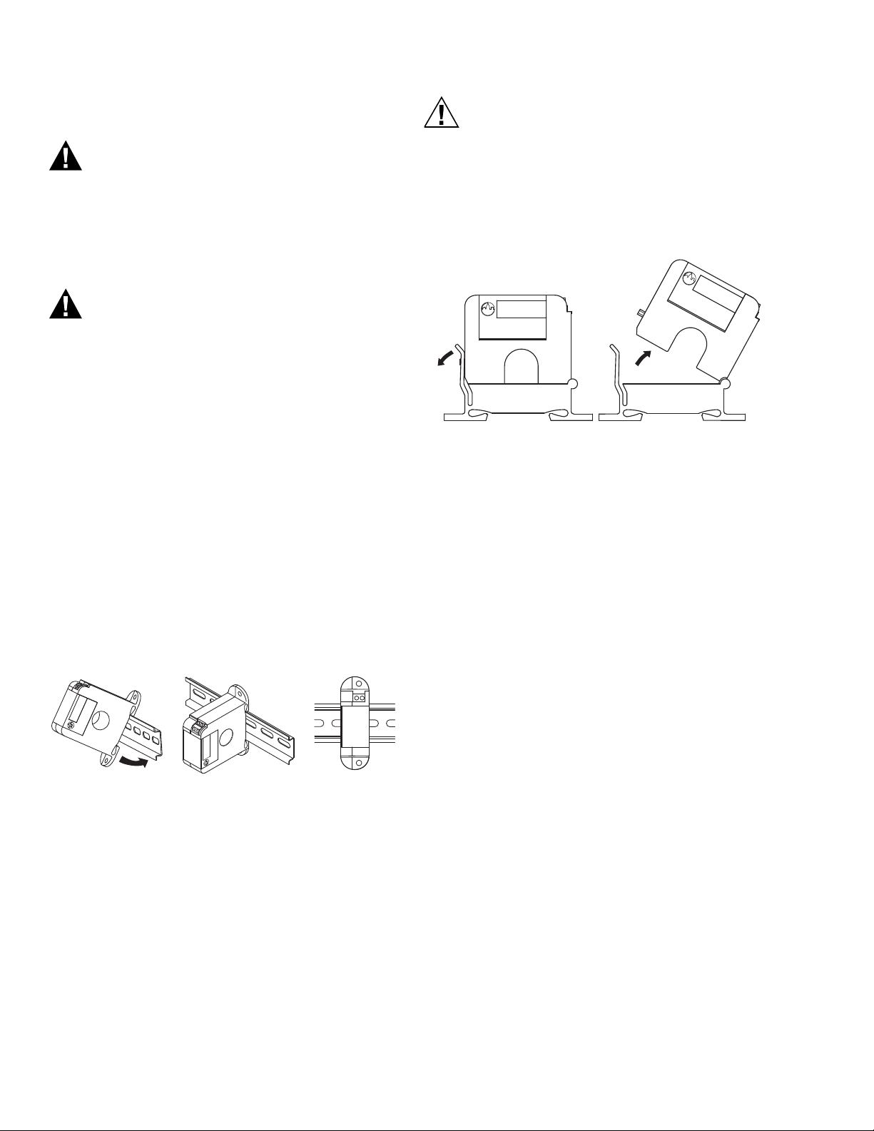
Fig. 1. Sensor Placed On Rail.
Latch Operation for CTP-A Series
Press down on the side tab and swing the top of the unit
up to open the split core current sensor as shown in Fig. 2.
Press down firmly on the cover to close the current sensor.
An audible “click” will be heard as the tab slides over the
tongue on the base.
CAUTION
Mating surfaces of the magnetic core are
exposed when the sensor is open. Electrical
contact grease, present on the cores to prevent
corrosion, can capture grit and dirt if care is not
exercised. Operation can be impaired if anything
prevents good contact between pole pieces.
Visually check the mating parts of the core
before closing the current sensor.
Fig. 2. Opening Split Core Models.
CURRENT SENSOR SETUP
The amperage range selected represents the maximum
current that can be applied to the conductor being
monitored. DO NOT EXCEED! All current sensors with
selectable ranges will have the range selection jumper
factory set on the high range. For models with field
selectable amperage ranges, select the correct amperage
range using the range selection jumper. Note that all RMS
models have True RMS outputs and should be used with
Variable Frequency Drives.
WIRING
We recommend the use of a two conductor 16 to 22 AWG
shielded cable, COPPER WIRE ONLY, for all 4 to 20mA
current sensor installations. A maximum wire length of
less than 30 meters (98.4 feet) should be used between
the current sensors and the Building Management
System or controller.
NOTE: When using a shielded cable, be sure to connect
only (1) end of the shield to ground at the control-
ler. Connecting both ends of the shield to ground
may cause a ground loop.
When removing the shield from the sensor end, make sure
to properly trim the shield to prevent any chance of
shorting. The current sensor terminals are polarity
sensitive and represent a linear and proportional 4 to
20mA output signal. The current sensors are available in
either an Average or True RMS output version. Tighten the
screws at the terminal block connections to the
recommended torque of 0.5 to 0.6 Nm (4.43 to 5.31 in-
lbs.). The aperture (hole) size of the current sensor is 0.75”
(1.90 cm).
M37378
M37379
SOLID CORE AND SPLIT CORE 4-20 MA OUTPUT CURRENT SENSORS
331-00142—01
Application Example
Fig. 3. Analog circuit.
TROUBLESHOOTING
Table 2. Troubleshooting.
CURRENT CONVERSION FORMULAS
WEEE DIRECTIVE
At the end of their useful life the packaging and product should be disposed of via a suitable recycling center. Do not
dispose of with household waste. Do not burn.
M37403
SHIELDED CABLE
AI
COMMON
GND (SHIELDED)
BUILDING AUTOMATION
SYSTEM
4 TO 20mA
SIGNAL INPUT
+
DC
POWER
SUPPLY
13.5 TO 30 VDC
–
Problem Solution
No reading • Confirm that you have +13.5 to 30VDC in series with the current sensor output terminals and the analog input of the
control panel.
• Check the polarity of the circuit.
• Verify that the terminals are screwed down, wires are firmly in place.
• Disconnect the input to the control panel and then insert a current meter (mA range) in series with the current sensor
output to verify that the circuit is working properly.
Erratic readings • Verify that the wires are terminated properly.
• Check that the +13.5 to 30VDC input is clean. In areas of high RF interference, shielded cable may be necessary to
stabilize signal.
Inaccurate readings • If you suspect that the current sensor is not reading within the accuracy specifications, please contact the factory for
assistance.
Current Sensor is operating at
a low-level current or failing to
operate within the accuracy
specifications.
• Visually check the mating parts of the core to ensure there is no debris between the split contacts. See Fig. 2.
• Remove all debris or dust manually and close the current sensor.
• Continue to retest the sensor in your application.
TO CONVERT THE CURRENT SENSOR OUTPUT SIGNAL TO A CURRENT READING:
4-20mA output to Current reading
(4mA = 0 Amps and 20mA = 250 Amps for A/CTA2-250)
Example: 12mA current sensor output signal
Total Span = 250 Amps
Multiplier = 20mA-4mA/Total Span = 0.064
(12mA-4mA)/0.064= 125 AMPS
SOLID CORE AND SPLIT CORE 4-20 MA OUTPUT CURRENT SENSORS
Home and Building Technologies
In the U.S.:
Honeywell
715 Peachtree Street NE
Atlanta, GA 30308
customer.honeywell.com
® U.S. Registered Trademark
© 2018 Honeywell International Inc.
31-00142—01 M.S. 04-18
Printed in United States
By using this Honeywell literature, you agree that Honeywell will have no liability for any damages arising out of your use or
modification to, the literature. You will defend and indemnify Honeywell, its affiliates and subsidiaries, from and against any
liability, cost, or damages, including attorneys’ fees, arising out of, or resulting from, any modification to the literature by you.
CHINA ROHS COMPLIANCE INFORMATION
ENVIRONMENT-FRIENDLY USE PERIOD (EFUP) TABLE
󴉆󸀮󴏵󱡽󳮹 SJ/T 11364 󵵙󸊿󲷢󶴹󱳷
O: 󸀮󶆺󸛋󴈄󲸓󵙀󸢹󲔩󸛋󸽩󱝾󳧟󴈄󲕓󸢹󴉿󳾒󱙆󵵙󲀯󹄡󲕓󲔩 GB/T 26572 󸊿󲷢󵵙󹢔󹄡󸉔󴭁󱝥󱘕
X: 󸀮󶆺󸛋󴈄󲸓󵙀󸢹󷋼󲻒󲔩󸛋󸽩󱝾󵵙󴍅󱘈󲕓󸢹󴉿󳾒󱙆󵵙󲀯󹄡󸤥󱲡 GB/T 26572 󸊿󲷢󵵙󹢔󹄡󸉔󴭁
This table is prepared in accordance with the provisions of SJ/T 11364.
O: Indicates that said hazardous substance contained in all of the homogeneous materials for this part is below the limit
requirement of GB/T 26572.
X: Indicates that said hazardous substance contained in all of the homogeneous materials for this part is above the limit
requirement of GB/T 26572.
󴉃󱳊󱮧󸀮󱯜󵵙󱯇󱝎󸽩󱝾󽘜󵵜󱘗󲀯󱞄󱠇󸤥󱲡󹢔󹄡󸉔󴭁󵵙󹢔󱳷󱡋󵫞󵙀󸢹
All other components, not listed in the table, do not contain restricted substances above the threshold level.
REGULATORY INFORMATION
FCC REGULATIONS: § 15.19 (A)(3)
This device complies with part 15 of the FCC Rules.
Operation is subject to the following two conditions:
1. This device may not cause harmful interference, and
2. This device must accept any interference received,
including interference that may cause undesired
operation.
IC REGULATIONS: RSS-GEN
This device complies with Industry Canada’s license-
exempt RSSs.
Operation is subject to the following two conditions:
1. This device may not cause interference; and
2. This device must accept any interference, including
interference that may cause undesired operation of
the device.
Le présent appareil est conforme aux CNR d’Industrie
Canada applicables aux appareils radio exempts de
licence. L’exploitation est autorisée aux deux conditions
suivantes :
1. l’appareil ne doit pas produire de brouillage;
2. l’utilisateur de l’appareil doit accepter tout brouil-
lage radioélectrique subi, même si le brouillage est
susceptible d’en compromettre le fonctionnement.
FCC WARNING (PART 15.21) (USA ONLY)
Changes or modifications not expressly approved by the
party responsible for compliance could void the user’s
authority to operate the equipment.
󸽩󱝾󱿽󶌇
Component
Name
󴈄󲸓󵙀󸢹 - Hazardous Substances
󹚮(Pb)
Lead (Pb)
󴭰(Hg)
Mercury (Hg)
󹜲(Cd)
Cadmium (Cd)
󱮺󱞀󹛕 (Cr6+)
Chromium VI
Compounds
(Cr6+)
󲡕󴼤󶾌󷔦 (PBB)
Polybrominate
d Biphenyls
(PBB)
󲡕󴼤󱛔󷔦󹂮
(PBDE)
Polybrominated
Diphenyl Ethers
(PBDE)
Assorted
capacitors
OOOO O O
Assorted resistors O O O O O O
Core OOOO O O
Screw OOOO O O