Using Alarms on the Honeywell HumidIcon™ Digital
Humidity/Temperature Sensors: HIH-6130/6131 Series
2Honeywell Sensing and Control
The contents of the alarm registers correspond to humidity as
follows:
Humidity (%RH) = RegisterContents
(214 - 1) x 100%
Thus, 0 %RH = 0x0000 and 100 %RH = 0x3FFF or 16383.
For example, to enable the Alarm_High output at humidity
above 80 %RH:
Alarm_High_On =
80 %RH
100% x (214 - 1) = 13107 or 0 x 3333
Similarly, to enable the Alarm_Low output at humidity below
10 %RH:
Alarm_Low_On =10 %RH
100% x (214 - 1) = 1638 or 0 x 0666
Alarm hysteresis is equivalent to the difference between the
registers.
A minimum hysteresis of 3% RH is recommended.
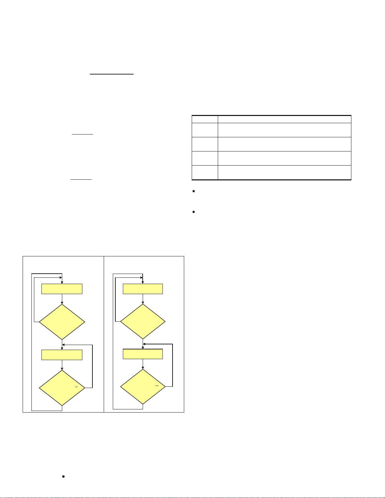
High and Low Alarm flow charts are shown in Figure 4.
Figure 4. High and Low Alarm Flow Charts
Alarm = Off
Measurement >
Alarm_High_On?
Alarm = On
Measurement <
Alarm_High_Off?
Yes
Yes
No
No
Alarm = Off
Measurement <
Alarm_Low_On?
Alarm = On
Measurement >
Alarm_Low_Off?
Yes
Yes
No
No
4.0 Alarm Configuration
A fifth register, the Customer Configuration Register (see
Appendix B), is associated with the alarm outputs and contains
the configuration bits. Both alarms may be configured
independently using the Alarm_Low_Cfg and Alarm_High_Cfg
bits (see Table 1).
Table 1. Customer Configuration Register Alarm Bits
Alarm_Low Polarity:
0 = Active_ High, 1 = Active_ Low
Alarm_Low Output Configuration:
0 = Full_Push-Pull, 1 = Open_Drain
Alarm_High Polarity:
0 = Active_High, 1 = Active_Low
Alarm_High Output Configuration:
0 = Full_Push-Pull, 1 = Open_Drain
For applications which interface to other logic circuits, such
as a micro-processor or to drive an external device, Full
Push-Pull is recommended.
For driving loads directly connected to the sensor voltage
supply open drain would be a typical choice (see Figures 1
and 2).
The polarity of the alarm output is configured using the Alarm
Polarity bits. The ability to change the alarm polarity gives the
user flexibility in how the sensor interfaces with an application.
In the example shown in Figure 1, the alarm outputs are used
to control an LED. For the LED to light up when the alarm is on
or active, the alarm output must be low, so the alarm polarity
bit should be set to 1, Active_Low.
5.0 Creating Two High or Two Low Alarms
The Alarm Polarity bits also give the user the option to create
two high alarms or two low alarms.
Consider an application requiring two high alarms.
Conventionally, if the Alarm_Low Polarity is configured as
Active High, then the Alarm_Low output will become active
(goes high) when the humidity falls lower than the humidity
value represented in the Alarm_Low_On register and
becomes inactive (goes low) when the humidity rises above
the humidity value represented in the Alarm_Low_Off register.
Similarly, if the Alarm_High Polarity is configured as Active
High, then the Alarm_High output will become active (goes
high) when the humidity rises above the humidity value
represented in the Alarm_High_On register and becomes
inactive (goes low) when the humidity falls below above the
humidity value represented in the Alarm_High_Off register (see
Figure 5).


