manuals.online logo
Brands
  1. Home
  2. •
  3. Brands
  4. •
  5. Honeywell
  6. •
  7. Accessories
  8. •
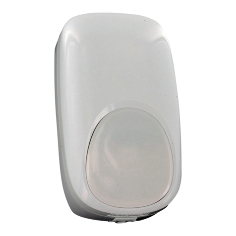
  9. Honeywell Dual Tec DT-500 User manual

Honeywell Dual Tec DT-500 User manual

Step 2
Separate sensor housings.
Insert small screwdriver into slot in bottom and push
up on latch. Then gently pull the housings apart at
the base.
Corner Mount
Knockouts
Wall Mount
Knockouts
DT-500 Series Animal Immune DUAL TEC® Motion Sensor Installation Instru tions
Step 1
Sele t the mounting lo ation.
Mount at 7'6" / 2.3 m for optimal animal
immunity.
Step 5
Wire the sensor.
Observing the proper polarity, wire the unit as
shown use 14-22 AWG). Push as much wire as
possible back into the wall when returning the PCB
to its housing.
Step 6
Walk-test the sensor.
Apply power to the sensor and let it warm up for
three minutes. Begin walk-test after the red LED
has stopped flashing.
Step 3
Remove the PCB.
Push down on the latch at the bottom of the
housing. Then gently pull the printed circuit board
PCB) forward and up by the terminal strip.
Step 4
Mount the sensor.
Carefully break out appropriate mounting knock-
outs on the rear housing, and mount it in the
desired location.
Walk across the protected area at the ranges to
be covered. The red LED will indicate an alarm
condition after two to four normal steps. When
there is no motion in the protected area, the LED
will be off.
Wiring Hole
Aim the DT-500/DT-500T
away from:
NOTE: For proper wiring methods, refer to the National
Electrical Code NFPA 70.
WARNING: DO NOT touch the antenna when removing
the PCB from the rear housing.
Antenna
Red Alarm LED
W1 Cut W1 Wire to
Disable LED)
Model DT-500T Only Model DT-500T Only
IntelliSense and DUAL TEC are registered trademarks of
Honeywell, Inc.
PRODUCT SPECIFICATIONS
Range:
DT-500, DT-500T
11 m x 9 m 35' x 30')
Alarm relay:
Energized Form A NC)
100 mA, 30 VDC
Tamper:
25 mA, 30 VDC
Power requirements:
10 - 14.5 VDC
35 mA, 12 VDC
RFI immunity:
30 V/m
10 MHz - 1000 MHz
PIR white light immunity:
6,500 Lux
Frequen ies:
Center band 2.45 GHz
Sensitivity:
2 - 4 steps within field of
view
SUPERVISION
If the microwave technology stops sending or receiving
signals, or the system electronics are not in normal working
order, the sensor's red LED will latch ON and alarm relay will
open.
The sensor can only recover from this state by cycling power.
If the problem still exists after cycling power, the sensor will
fail the power-up self-test, the red LED will latch ON, and
alarm relay will open. Self-test is performed at power-up and
every two hours after that.
NOTE: The sensor should be tested at least on e ea h year
to ensure proper operation.
DT-500 Series DUAL TEC® Motion Sensor Supplemental Information
DETECTION PATTERNS
TOP VIEW
Wall Mounted
Wide Angle Lens with Microwave Pattern
SIDE VIEW
Wide Angle Lens
FCC Noti e: This equipment has been tested and found to comply with
the limits for a field disturbance sensor, pursuant to Part 15 of the FCC Rules.
The user is cautioned that changes or modifications not expressly approved
by IntelliSense could void the user's authority to operate this equipment.
This equipment has been tested and found to comply with the limits for a Class
B digital device, pursuant to Part 15 of the FCC Rules. These limits are
designed to provide reasonable protection against harmful interference in a
residential installation. This equipment generates, uses and can radiate radio
frequency energy and, if not installed and used in accordance with the
instructions, may cause harmful interference to radio communications. How-
ever, there is no guarantee that interference will not occur in a particular
installation. If this equipment does cause harmful interference to radio or
television reception, which can be determined by turning the equipment off
and on, the user is encouraged to try to correct the interference by one or more
of the following measures:
 Reorient or relocate the receiving antenna.
 Increase the separation between the equipment and receiver.
 Connect the equipment into an outlet on a circuit different from that to
which the receiver is connected.
 Consult the dealer or an experienced radio/TV technician for help.
IC Noti e: Operation is subject to the following two conditions: 1) this
device may not cause interference, and 2) this device must accept any
interference, including interference that may cause undesired operation of
the device.
This device requires a radio licence, unless it is installed totally inside a
building. User must obtain this licence.)
Une licence est requise pour ces dispositifs, sauf pour ceux installés tout à fait
à l'intérieur d'un bâtiment. Il faut que l'utilisateur obtienne cette licence.)
All Rights Reserved
Copyright 2001 IntelliSense.
5-051-502-00 Rev H
Operating temperature:
-10° to 49° C 14° to 120° F)
UL: 0o to 49o C 32o to 120o F))
PIR fields of view (edges):
Standard lens
22 long range
12 intermediate
6 lower
4 down
Dimensions:
13 cm x 7 cm x 4 cm
5" H x 2-7/8" W x 1-5/8" D
Weight:
200 g 7 oz)
Packaged product:
260 g 9 oz)
Approvals/listings:
FCC certified
IC certified
UL listed
ULC Listed*
C-Tick
IMPORTANT: This sensor does not respond to walk-tests
in a conventional manner. Rather, it tracks motion and
analyzes the signals to confirm a valid alarm condition.
Internally the sensor registers, then confirms an alarm con-
dition. To observe this, take 2 to 4 steps into the pattern then
stop and watch the LED.
ANIMAL IMMUNITY
To achieve the highest level of attainable animal immunity,
please use the following recommended mounting guide-
lines:
 Mount the sensor at the standard height of 2.3 m
7' 6").
 Make sure an animal cannot get within 1.9 m 6')
of the sensor, such as by jumping on furniture or
shelving.
 Make sure the sensor is level with the wall. Use
a leveling tool and position it vertically across
the face of the sensor. Improper installation can
reduce animal immunity levels.
 Make sure the sensor has a clear line-of-sight to all
areas you wish to protect. If the PIR sensor is blocked,
the unit will not alarm.
 Aim the sensor toward the interior of the room, point-
ing away from windows, moving machinery, and heat-
ing/cooling sources.
Each installation should be tested to determine the level of
attainable animal immunity, and tested again whenever the
animal configuration changes. The following worksheet
provides additional guidelines for determining the level of
expected immunity:
NOTE: Animal immunity characteristics have not been verified by
Underwriter's Laboratories, Inc.
IMPORTANT: For UL certificated installations, the DT-500 must be con-
nected to a UL listed power supply or UL listed control unit capable of
providing a minimum of four hours of standby power.
*NOTE: The ULC label or listed marking on a product is the only evidence
provided by Underwriters Laboratories of Canada to identify products that
have been produced under the Listing and Follow-up Service.
This Class B digital apparatus meets all requirements of the Canadian
Interferen e-Causing Equipment Regulations.
Cet appareil numérique de la lasse B respe te toutes les exigen es du
Règlement sur le matériel brouilleur du Canada.
SUPERVISION
If the microwave technology stops sending or receiving
signals, or the system electronics are not in normal working
order, the sensor's red LED will latch ON and alarm relay will
open.
The sensor can only recover from this state by cycling power.
If the problem still exists after cycling power, the sensor will
fail the power-up self-test, the red LED will latch ON, and
alarm relay will open. Self-test is performed at power-up and
every two hours after that.
NOTE: The sensor should be tested at least on e ea h year
to ensure proper operation.
ANIMAL IMMUNITY WORKSHEET
Total combined animal weight s) 45 kg 100 lb.)
Flooring Material: Flooring materials within the sensors field-
of-view will effect the levels of animal immunity. Generally, a
carpeted floor will achieve a higher level of immunity than a
cement floor.
Carpet: deduct 0
Wood: deduct 2.25 kg 5 lb.)
Tile/Cement: deduct 4.5 kg 10 lb.) -
___________
Animal Heat Radiation*: Generally, the longer the hair on
an animal, the less heat or infrared energy they radiate. A
long hair animal tends to achieve a higher level of animal
immunity than a short hair animal.
Long Hair: deduct 0
Medium Hair: deduct 2.25 kg 5 lb.)
Short Hair: deduct 4.5 kg 10 lb.) -
___________
Estimated animal immunity level =
___________
*Use in installations with dogs and cats.
²½Öè 2
´ò¿ªÌ½²âÆ÷µÄÍâ¿Ç¡£
ÓÃÒ»¸öСÂÝË¿µ¶²åÈë̽²âÆ÷µ×²¿µÄС¿×£¬²¢Ñ¹Ï´𹳣¬
È»ºóÇáÇáµØÈ¡ÏÂǰ¸Ç¡£
ǽ½Ç°²×°¿× Ç½Ãæ°²×°¿×
DT-500 ϵÁп¹¶¯ÎïÎó±¨DUALTEC®Ë«¼øÒƶ¯Ì½²âÆ÷°²×°ËµÃ÷
²½Öè 1
Ñ¡Ôñ°²×°¸ß¶È¡£
ÄÜ´ïµ½×î¼Ñ¿¹¶¯ÎïÎó±¨Ð§¹ûµÄ°²×°¸ß¶ÈΪ
2.3Ãס£
²½Öè 5
½ÓÏß¡£
°´ÈçÏ·½·¨£¬ÓÃ14-22 AWGµÄµ¼Ïß½ÓÏß¡£½ÓÏßÍê±Ï
ºó £¬Ó¦¾¡Á¿½«µ¼ÏßÀ»ØÇ½ÄÚ¡£
²½Öè 6
²½²â¡£
¶Ô̽²âÆ÷Éϵ磬²¢Ê¹ÆäÔ¤ÈÈ3·ÖÖÓ¡£µ±ºìÉ«LED
Í£Ö¹ÉÁ˸ºó£¬·½¿É¿ªÊ¼²½²â¡£
²½Öè 3
È¡ÏÂÓ¡Ë¢µç·°å¡£
½«ºó¸Çµ×²¿µÄ´ð¹³ÏòÍâ°å£¬È»ºóÇáÇáµØÈ¡ÏÂ
Ó¡Ë¢µç·°å¡£
²½Öè4
°²×°Ì½²âÆ÷¡£
СÐĵØÔä´©ºó¸ÇÉϵݲװ/½øÏßÔ¤ÖÆ¿×£¬²¢½«ºó¸Ç
¹Ì¶¨ÓÚÔ¤¶¨µÄλÖá£
ÔÚ̽²âÆ÷µÄ̽²âÊÓÇø·¶Î§ÄÚ½øÐв½²â¡£²½²âÕßÔÚ
ÊÓÇøÄÚÒÔÕý³£²½ËÙÐÐ×ß2ÖÁ4²½£¬Ó¦ÄܵãÁÁ±¨¾¯LED¡£
µ±Ì½²âÊÓÇøÄÚûÓÐÎïÌåÒÆ¶¯Ê±£¬±¨¾¯LED½«»áϨ
Ãð¡£
½ø³öÏß¿×
DT-500/DT-500TÓ¦±Ü¿ª´°
»§¡¢ÀäÈÈÔ´¼°¿ª¶¯µÄ»úÆ÷
×¢Ò⣺ÕýÈ·µÄ½ÓÏß·½Ê½Çë²ÎÕÕ NFPA 70Ëùʾ¡£
¾¯¸æ£º ÔÚÈ¡PCBµÄ¹ý³ÌÖÐÇëÎð½Ó´¥ÌìÏß¡£
ÌìÏß
ºìÉ«±¨¾¯ LED
W1 ¶Ï¿ªW1 µ¼ÏßÄÜ
¹Ø±Õ LED)
½öDT-500T ½ö DT-500T
·À²ð¶Ë×Ó
µçÔ´¶Ë×Ó
±¨¾¯¶Ë×Ó
DUAL TEC ÊÇ Honeywell, Inc. µÄ ×¢ ²á ÉÌ ±ê
IntelliSense ÊÇ Honeywell, Inc. µÄ ×¢ ²á ÉÌ ±ê
²úÆ·ÌØÐÔ£º
̽²â·¶Î§£º
DT-500, DT-500T
11 m x 9 m 35' x 30')
±¨¾¯¼ÌµçÆ÷£º
Àø´ÅAÐÍ ³£±Õ)
100 mA, 30 VDC
·À²ð£º
25 mA, 30 VDC
µçÔ´ÒªÇó£º
10 - 14.5 VDC
35 mA, 12 VDC
¿¹·øÉä¸ÉÈÅ£º
30 V/m
10 MHz - 1000 MHz
¿¹°×¹â¸ÉÈÅ£º
6,500 Lux
΢²¨ÆµÂÊ£º
2.45 GHz
ÁéÃô¶È£º
̽²âÊÓÇøÄÚ2 - 4 ²½
¼à¿Ø
Èç¹û΢²¨Í£Ö¹·¢ËÍ»ò½ÓÊÕÐźţ¬»òϵͳÄÚ²¿µÄµç×ӵ練¦ÓÚ
·ÇÕý³£¹¤×÷״̬£¬Ì½²âÆ÷µÄºìÉ«LED½«µãÁÁ²¢±»Ëø¶¨£¬±¨¾¯
¼ÌµçÆ÷Ò²½«´ò¿ª¡£
ÖØÐÂÉϵç¿ÉÄÜʹ̽²âÆ÷»Ö¸´Õý³£µÄ¹¤×÷״̬¡£Èç¹ûÉϵçºóÈÔ
²»Äܽâ¾öÎÊÌ⣬˵Ã÷̽²âÆ÷ûÓÐͨ¹ýÉϵç×Լ죬ºìÉ«LED½«
³ÖÐøµãÁÁ£¬±¨¾¯¼ÌµçÆ÷Ò²½«´ò¿ª¡£Ì½²âÆ÷Ò»°ãÉϵçºó¼´½øÈë×Ô
¼ì״̬£¬´Ëºóÿ¸ôÁ½Ð¡Ê±»á½øÐÐÒ»´Î×Լ졣
×¢£ºÎª±£Ö¤Ì½²âÆ÷ÄÜÕý³£µØ¹¤×÷Ó¦ÖÁÉÙÿÄê¶Ô̽²âÆ÷½øÐÐ
ÒÀ´Î¼ì²â¡£
̽²âÊÓÇøÍ¼
¶¥ÊÓͼ
Ç½Ãæ°²×°
¹ã½Ç͸¾µ
²àÊÓͼ
¹ã½Ç͸¾µ
°æ Ȩ Ëù ÓÐ 2001 IntelliSense.
5-051-502-00 Rev H
¹¤×÷ζȣº
-10° to 49° C 14° to 120° F)
UL: 0o to 49o C 32o to 120o F))
PIR ̽²âÊÓÇø (±ßÔµ):
±ê׼͸¾µ
22 Ô¶Çø
12 ÖÐÇø
6 ½üÇø
4 ¸©ÊÓÇø
ÍâÐͳߴ磺
13 cm ³¤x 7 cm ¿íx 4 cm¸ß
ÖØÁ¿£º
200 g 7 oz)
´ø°ü×°£º
260 g 9 oz)
¹ú¼ÊÈÏÖ¤£º
FCC
IC
UL listed
ULC Listed*
C-Tick
×¢Òâ: Ó봫ͳµÄ²½²â·½·¨²»Í¬£¬DT-500ϵÁÐ̽²âÆ÷¸ú×ÙÒÆ
¶¯µÄÎïÌå½øÐв¢¶ÔÆä·¢³öµÄÐźŽøÐзÖÎö¡¢Åжϣ¬È»ºóÈ·¶¨
ÊÇ·ñ±¨¾¯¡£²½²âʱ£¬ÔÚ̽²âÊÓÇøÄÚ²½ÐÐ2-4²½£¬È»ºóÍ£ÏÂ
À´¹Û²ìLEDָʾµÆ¡£
¿¹¶¯ÎïÎó±¨
Ϊ»ñµÃ×î¼ÑµÄ¿¹¶¯ÎïÎ󱨵ÄЧ¹û£¬Çë²ÎÕÕÒÔϵÄָʾ£º
 °²×°¸ß¶ÈΪ 2.3 Ã×
 È·±£¾à̽²âÆ÷1.9 Ã׵ķ¶Î§nÄÚûÓÐС¶¯Î±ÈÈçÌøÉÏ
¼Ò¾ß»ò¼Ü×ÓÉϵÄС¶¯Îï¡£
 È·±£Ì½²âÆ÷ÓëÇ½Ãæ±£³ÖƽÐС£Ó¦Ê¹Óù¤¾ß½øÐÐУ
× ¼ ¡£²» ÕýÈ·µÄ°²×°»áµ¼Ö¿¹Î󱨵ÄЧ¹û¡£
 È·±£Ì½²âÆ÷ÔÚ±»±£»¤µÄÇøÓòÄÚÓÐÒ»¸öÇåÎúµÄÊÓÏß¡£
Èç¹ûºìÍâ»ò΢²¨±»ÕÚµ²£¬Ì½²âÆ÷½«ÎÞ·¨±¨¾¯¡£
 ̽²âÆ÷Ó¦Ö¸ÏòÊÒÄÚ£¬Í¬Ê±Ó¦±Ü¿ª´°»§¡¢ÕýÔÚÔËתµÄ
»ú Æ ÷ÒÔ¼°ÀäÈÈÔ´¡£
½¨Òéÿ´Î°²×°ºó¶¼Òª¶Ô̽²âÆ÷½øÐвâÊÔ£¬ÒÔÈ·¶¨Êµ¼Ê¿ÉÒÔ´ïµ½µÄ
¿¹¶¯ÎïÎ󱨵ÄЧ¹û¡£Ï±íΪ¿¹¶¯ÎïÎ󱨵ÄЧ¹û¶ÔÕÕ±í¡£
¿¹¶¯ÎïÎó±¨Ð§¹û²ÎÕÕ±í
ËùÓж¯ÎïÖØÁ¿×ÜºÍ s) 45 kg 100 lb.)
µØ°å²ÄÁÏ£º ̽²âÊÓÇøÄڵĵذå²ÄÁÏÓ°Ïìµ½¿¹¶¯ÎïÎ󱨵ÄЧ
¹û ¡£Ò»°ãÀ´Ëµ£¬ÆÌÁ˵ØÌºµÄµØ°å±ÈË®ÄàµØ°å¿¹¶¯ÎïÎ󱨵Ä
Ч¹ûÒªºÃЩ¡£
µØÌº£º ¼õ 0
ľµØ°å£º ¼õ 2.25 kg 5 lb.)
µØ×©/Ë®Äࣺ ¼õ 4.5 kg 10 lb.) - ___________
¶¯ÎïÈÈÁ¿¼°ºìÍâ·øÉä*£º Ò»°ãÀ´Ëµ£¬¶¯ÎïµÄë·¢Ô½³¤£¬É¢
·¢µÄÈÈÁ¿ºÍºìÍâ ÄÜÁ¿Ô½ÉÙ¡£Òò´Ë¶ÔÓÚ³¤Ã«¶¯ÎïµÄ¿¹Îó±¨Ð§
¹ûÒª±È¶ÌëµÄЧ¹ûºÃ¡£
³¤Ã«£º ¼õ 0
Öеȣº ¼õ 2.25 kg 5 lb.)
¶Ì ë £º ¼õ 4.5 kg 10 lb.) - ___________
¹À¼ÆµÄ¿¹¶¯ÎïÎó±¨Ð§¹û = ___________
*ÔÚ°²×°¹ý³ÌÖÐÓù·»òè×÷²âÊÔ¡£
× ¢ £ º Óë DT-500 Ïà½Ó²µµÄµçÔ´»ò¿ØÖÆÖ÷»ú±ØÐëͨ¹ýULÈÏÖ¤
² ¢±£Ö¤ÖÁÉÙ4Сʱ±¸µç¹©Ó¦¡£
FCC ÉùÃ÷£º ¸ÃÉ豸¾-²âÊÔ·ûºÏFCC¹æÔòÖеÚ15ÕµÄÓйذ²×°Ì½
²âÆ÷¶ÔÇøÓò²úÉú¸ÉÈÅÌõ¿îµÄ¹æ¶¨¡£±¾¹«Ë¾ÉùÃ÷¶ÔÓû§Ë½×Ô¸ü¸ÄÉè
±¸¶øµ¼Öµĺó¹û¸Å²»¸ºÔð¡£
¸ÃÉ豸¾-²âÊÔ·ûºÏFCC¹æÔòÖеĵÚ15ÕÂÓйذ²×°Ì½²âÆ÷¶ÔÇøÓò
²úÉú¸ÉÈÅÏÞÖÆ¹æ¶¨¡£Èç¹û²»°´ÕÕ°²×°ËµÃ÷½øÐа²×°£¬¸ÃÉ豸Éú
³ÉµÄÎÞÏß·øÉäÄÜÁ¿»á¶ÔÎÞÏßµçÉ豸 ²úÉú¸ÉÈÅ¡£È»¶ø£¬ÔÚ°²×°ÖÐ
ÎÞ·¨±£Ö¤Ã»ÓиÉÈÅÉú³É¡£Èç¹û¸ÃÉ豸¶ÔÎÞÏßµçºÍµçÊÓ»úµÄ½ÓÊÕ
²úÉú¸ÉÈÅ£¬¿ÉÒԹرոÃÉ豸£¬»ò°´ÈçÏ·½·¨¼õÉÙ¸ÉÈÅ£º
•µ÷Õû½ÓÊÕÌìÏß¡£
• Ôö¼Ó¸ÃÉ豸ÓëÎÞÏßµçÉ豸¼äµÄ¾àÀë¡£
•ÓëÎÞÏßµç½ÓÊÕÉ豸µÄµç··Ö¿ª¡£
•ÏòÓÐ¹ØµÄ ÎÞÏßµç/µçÊÓ»úµÄ³§É̽øÐм¼Êõ×Éѯ¡£
IC ÉùÃ÷£ºÉ豸µÄʹÓÃÓ¦»ùÓÚÒÔÏÂÁ½¸öÌõ¼þ£º(1) ¸ÃÉ豸²»»áµ¼ÖÂ
¸ÉÈÅ £»¶øÇÒ(2)¸ÃÉ豸ÄÜ¿¹ÈκΰüÀ¨ÒâÍâ²Ù×÷¶ø²úÉúµÄ¸ÉÈÅ¡£
DT-500 ϵÁÐDUALTEC®Ë«¼øÒƶ¯Ì½²âÆ÷²¹³ä˵Ã÷

This manual suits for next models

1

Other Honeywell Accessories manuals

Honeywell RDWL515A2000 Operating instructions

Honeywell

Honeywell RDWL515A2000 Operating instructions

Honeywell LLE Series User manual

Honeywell

Honeywell LLE Series User manual

Honeywell E3Point User manual

Honeywell

Honeywell E3Point User manual

Honeywell SiX series User manual

Honeywell

Honeywell SiX series User manual

Honeywell K594.RF User manual

Honeywell

Honeywell K594.RF User manual

Honeywell RPW202A User guide

Honeywell

Honeywell RPW202A User guide

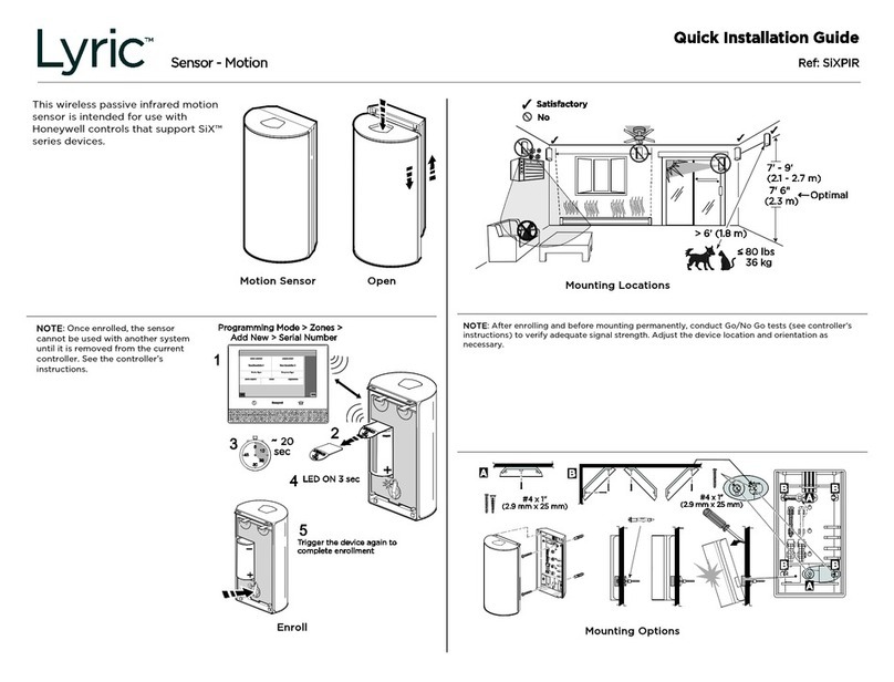
Honeywell Lyric SIXPIR User manual

Honeywell

Honeywell Lyric SIXPIR User manual

Honeywell IAQPoint2 User manual

Honeywell

Honeywell IAQPoint2 User manual

Honeywell PRO 2000 Series Operation manual

Honeywell

Honeywell PRO 2000 Series Operation manual

Honeywell T9 User manual

Honeywell

Honeywell T9 User manual

Honeywell RPWL100A User manual

Honeywell

Honeywell RPWL100A User manual

Honeywell RPW316A Manual

Honeywell

Honeywell RPW316A Manual

Honeywell CAMIR-N User manual

Honeywell

Honeywell CAMIR-N User manual

Honeywell RF 20 User manual

Honeywell

Honeywell RF 20 User manual

Honeywell Ex-Or LightSpot Silver Series Installation and operation manual

Honeywell

Honeywell Ex-Or LightSpot Silver Series Installation and operation manual

Honeywell 2450Cm Series User manual

Honeywell

Honeywell 2450Cm Series User manual

Honeywell DW311S User manual

Honeywell

Honeywell DW311S User manual

Honeywell RTY Series User manual

Honeywell

Honeywell RTY Series User manual

Honeywell 5870API Assembly instructions

Honeywell

Honeywell 5870API Assembly instructions

Honeywell DC515 P2/BS Series User manual

Honeywell

Honeywell DC515 P2/BS Series User manual

Honeywell Fire-Lite Alarms AD365A User manual

Honeywell

Honeywell Fire-Lite Alarms AD365A User manual

Honeywell CAMIR User manual

Honeywell

Honeywell CAMIR User manual

Honeywell DC311 Series User manual

Honeywell

Honeywell DC311 Series User manual

Honeywell RPW102 User manual

Honeywell

Honeywell RPW102 User manual

Popular Accessories manuals by other brands

Crestron 1700C-BTNB-BEZEL Operations & installation guide

Crestron

Crestron 1700C-BTNB-BEZEL Operations & installation guide

PASCO PS-3202 Replacement instructions

PASCO

PASCO PS-3202 Replacement instructions

Kohler K-8787X-B03 Installation and care guide

Kohler

Kohler K-8787X-B03 Installation and care guide

SUTO S 120 Instruction and operation manual

SUTO

SUTO S 120 Instruction and operation manual

Tobii TX300 manual

Tobii

Tobii TX300 manual

Master Instruments iFighter-1500 instruction manual

Master Instruments

Master Instruments iFighter-1500 instruction manual

Prolitec AIRQ AQ160 Original instructions

Prolitec

Prolitec AIRQ AQ160 Original instructions

Pfannenberg DTT 6 01 Series Operating and assembly instructions

Pfannenberg

Pfannenberg DTT 6 01 Series Operating and assembly instructions

Middle Atlantic Products Display Station Series installation instructions

Middle Atlantic Products

Middle Atlantic Products Display Station Series installation instructions

TLC SEC150 introduction

TLC

TLC SEC150 introduction

Intenso Powerbank S6000 manual

Intenso

Intenso Powerbank S6000 manual

Wsky AKZ-M4 quick start guide

Wsky

Wsky AKZ-M4 quick start guide

Madas SEISMIC M90 manual

Madas

Madas SEISMIC M90 manual

Vaisala HMP60 series user guide

Vaisala

Vaisala HMP60 series user guide

Isimet FGS-3X13 Installation, Operations, Start-up and Maintenance Instructions

Isimet

Isimet FGS-3X13 Installation, Operations, Start-up and Maintenance Instructions

Vadsbo CBU-PIRDALI-W manual

Vadsbo

Vadsbo CBU-PIRDALI-W manual

Sunforce WIND TURBINE TOWER KIT user manual

Sunforce

Sunforce WIND TURBINE TOWER KIT user manual

Seifert SlimLine Pro KG 8503 instruction manual

Seifert

Seifert SlimLine Pro KG 8503 instruction manual

manuals.online logo
manuals.online logoBrands
  • About & Mission
  • Contact us
  • Privacy Policy
  • Terms and Conditions

Copyright 2025 Manuals.Online. All Rights Reserved.