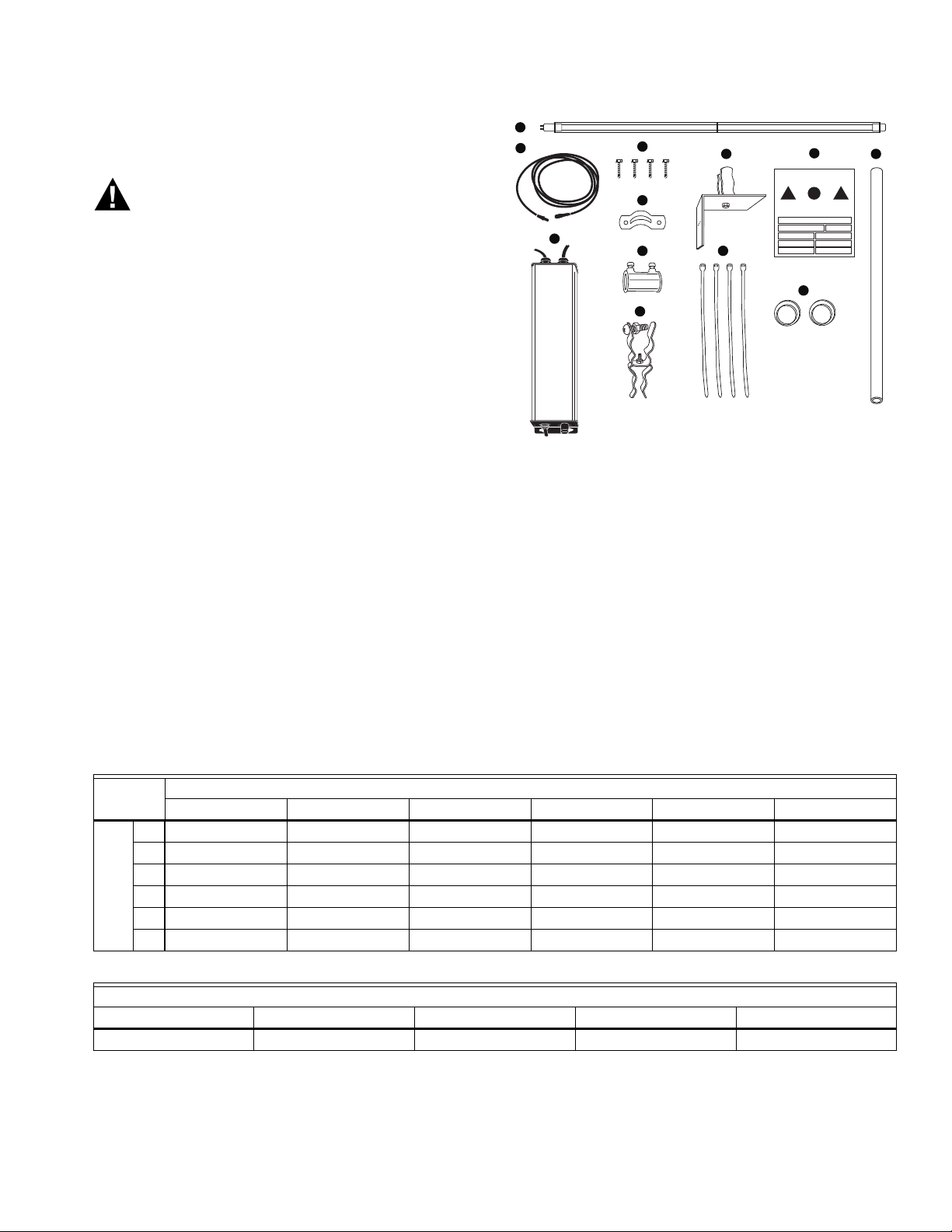
UVL-COIL ULTRAVIOLET LAMP KITS FOR AHU COILS
31-00402—02 6
Fig. 8. Installing UV Lamp.
Mount Power Supply(s)
Mount the power supply in a location (inside or outside of
the HVAC system) that is convenient for access to the main
power supply and for connection to the UV lamps. The
power supply is weather resistant and is suitable for
mounting inside or outside of the air handler.
Use the supplied self-taping sheet metal screws to mount
the power supply in place through the mounting holes on
the sides of the base. It is recommended to use wire boxes,
cable strain relief fittings, or other sealing methods in order
to pass the power cord and lamp cables into the interior of
the air handler for connections.
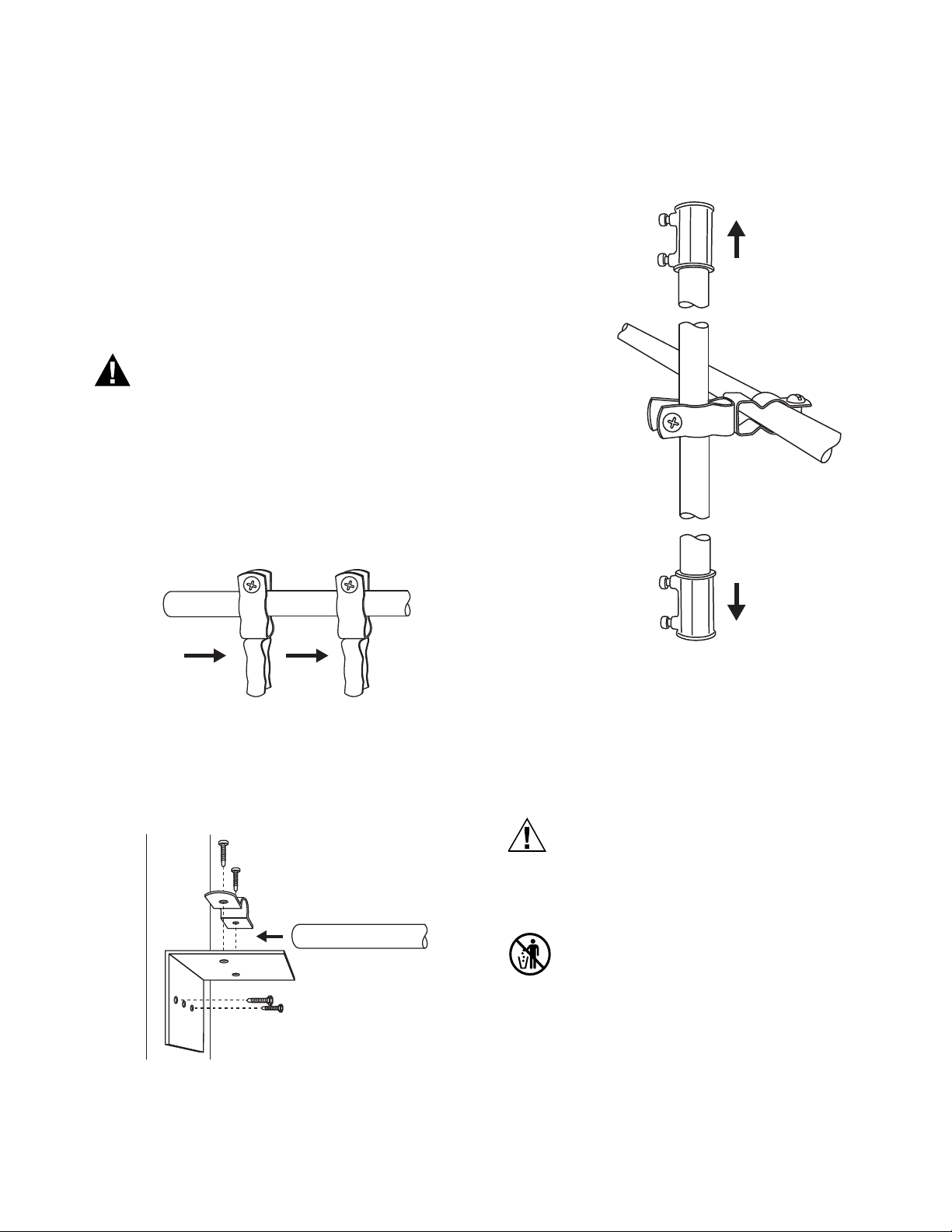
Sight Glass Installation
The sight glass allows safe viewing of the UV light system
when in operation. Find a suitable location such as a door
to the HVAC system for the sight glass. Drill a 1” hole and
press the base of the sight glass through it.
Fig. 9. Sight Glass Installation.
WIRING
Electric Shock Hazard.
Can cause personal injury.
Turn off main power before making electrical
connections.
Refer to electrical diagram (Fig. 10.) for proper connections
of the power supply to the main power.
Fig. 10. Electrical Connections.
Connect Lamps and Cables
Arrange cables as needed for installation. If necessary, use
cable strain relief fittings or other means to pass cables
through the cabinets or air system walls. When UV lamps,
power supplies, and cables are in place join the lamp and
power supply cables by aligning the electrical pins and
flanges on the rubber connectors and pushing them firmly
together.
Fig. 11. Align Pins and Lamp Key.
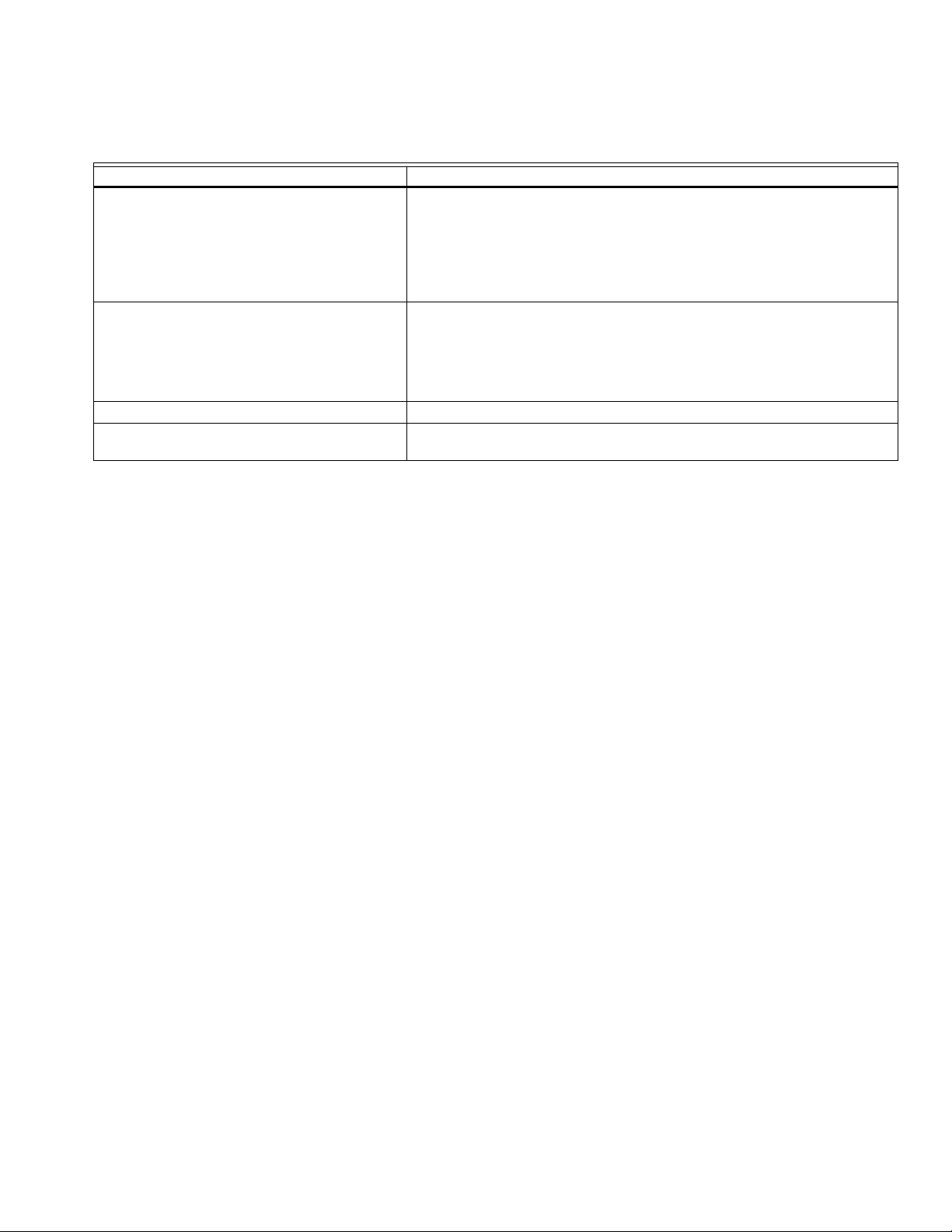
MAINTENANCE
Honeywell UVC lights are made of Hard Quartz. Unlike Soft
Quartz, these lamps do NOT need to be wiped of grease or
other contaminants, and are NOT affected by humidity.
They are warranted for 2 years of UVC output, to 60% of
their original output. Sizing guidelines are based on the
end of lamp life output levels.
Honeywell UV lamps are rated for two years germicidal
effectiveness. The visible blue light will continue to
illuminate, but does NOT have any germicidal
effectiveness. Bulbs must be replaced on schedule for the
system to function properly.
IMPORTANT
Use only Honeywell replacement lamps. Use of
replacement lamps from other manufacturers
voids the warranty. See Table 1 for replacement
lamp part numbers.
UV LAMP
UV LAMP
120-277 VAC
POWER SUPPLY
L1 BLACK
CONNECTORS
L2 or N WHITE
GND GREEN
Align Pins & Lamp Key
Push Firmly Together
UV Lamp
Power Supply
Cable
Lamp Key