Honeywell TA3840 User manual

Data Processing Racks
TA3840
Installation Manual
SAS au Capital de 2 158 244
€
- 444 871 933 R.C.S. Bourges - APE : 2651B
Headquarter: 9, rueIsaac Newton- 18000 Bourges - France

Data Processing Racks
Installation Manual
TA3840
1st
Edition
Released February 2013

INTRODUCTION
This manual is issued specifically for the data processing racks of the TA3840 or EMx40 system. It
contains instructions detailed for the installation of this system.
To use it in an optimal way, we advise you TO READ CAREFULLY THESE
INSTRUCTIONS and to respect them throughout the life of the equipment.
Keep this manual to hand so that you can refer to it at any time. Ensure that it is
complete and kept close to the equipment.
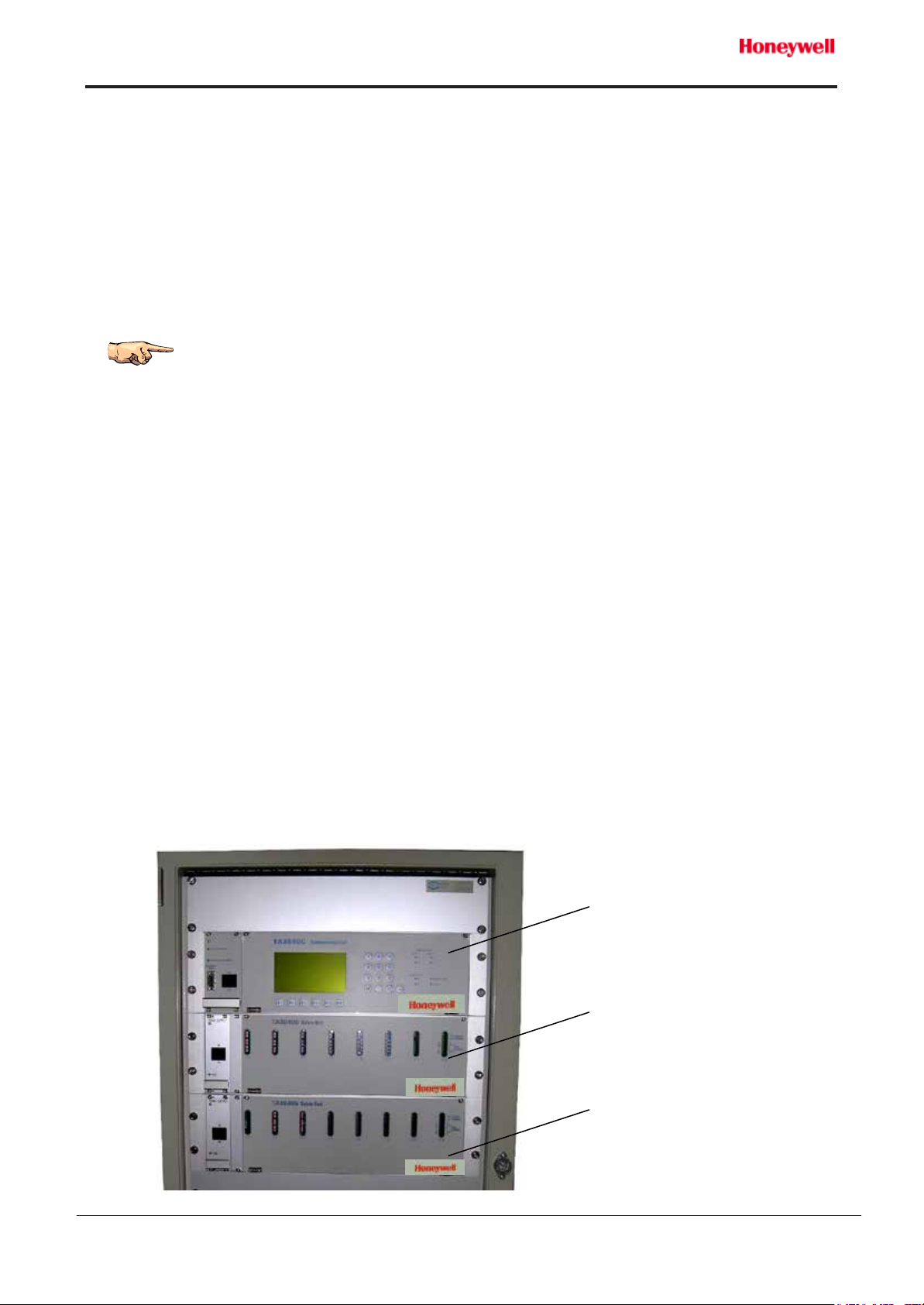
The racks TA3840C and TA3840S, as well as the TA3840R repeater module are integrated in the
system for processing the tankers liquid cargo. This system is intended for professional use, it
must be used by operators who are qualified and well-versed in the operating rules and safety
instructions set out in this manual.
We also draw your attention to the fact that the connection of equipments or the use of products
other than those recommended by Honeywell Marine may present risks for which we will not be
liable.
This manual must not be reproduced in any form whatsoever without the prior written approval of
Honeywell Marine who cannot be held responsible for any use of the information contained in this
manual.
As we want you to take advantage of the most of the latest technology and new equipment, as well
as to benefit from our experience, our equipments may undergo technical or design changes. As a
result, some of the features and information in this manual may change without prior notice and
without any obligation to up-date it.
Should you encounter any problems or have any questions about your TA3840 or EMx40 system,
please do not hesitate to contact your nearest Honeywell Marine customer service.
Other documents
The description and the operation of the racks TA3840C/R and TA3840S are described in the
MT5008E technical manual.
The maintenance of the racks TA3840C/R and TA3840S is described in the MM5008E
maintenance manual.
SAFETY PRECAUTIONS:
In order to avoid the electric shock or fire hazards, do not expose the equipments to
water projections. Take care to switch the power off before proceeding to any
disconnection or removal of the racks.
Never introduce parts, in particular metal ones, in the air vents of the racks.
Ensure that the racks are well ventilated and that the air vents are not covered.
Take care to maintain the racks distant from all heat sources (heating appliances…).

Regulation marking
The manufacturer and specifications plate of TA3840S rack is stuck on the rear face.
Warning:
Our equipments are designed and manufactured in accordance with local
safety regulations, and in particular European directives relative to reconciling
member states' legislation:
●89/336/EEC and 2004/108/EC "Electromagnetic compatibility",
●ATEX 94/9/EC"Equipment and protective systems intended for use in
potentially explosive atmospheres",
●96/98/EC "Marine equipment".
They are intended for professional use and must be installed, used and
maintained by competent staff that is qualified in this type of equipment.
In particular we wish to draw your attention to the fact that we cannot be held
responsible if:
●Any technical alterations are made to our appliances without our written
authorisation,
●Our equipments are damaged by being operated in conditions other than
the intended usage of their technical classification (power supply,
temperature, environment, etc.).
The safety instructions given in this manual are merely given for guidance
purposes to protect you and all those using and working on our equipments.
Honeywell Marine cannot foresee all dangerous situations that might arise.
This is why the owner and/or the operator is responsible for the operating
safety of the system.
Regulations of the ship classification society may impose procedures
(health and safety, fire prevention, handling of hazardous substances,
etc.), which are stricter than those given in this manual. In this case, the
regulations must be followed.
Manufacturer's name
and address
Serial
number
EC marking for directive 94/9/EEC,
equipment
- class IIB (refer to
"Technical specifications" paragraph
of the technical manual)
EC marking for directive 94/9/EEC, equipment -
class IIC (refer to "Technical specifications"
paragraph of the technical manu
al)
Manufacturing
month and year

TABLE OF CONTENTS
1. UNPACKING AND STORAGE..................................................................................................... 6
Recommendations .....................................................................................................................6
Storage.......................................................................................................................................6
2. SYSTEM DESCRIPTION.............................................................................................................6
Presentation...............................................................................................................................6
3. INSTALLATION OF THE RACKS.................................................................................................7
4. CONNECTION OF THE RACKS..................................................................................................7
TA3840C - Communication unit..................................................................................................7
TA3840C A/D- Analog data collection unit................................................................................ 10
TA3840S - Safety unit .............................................................................................................. 12
5. TA3840R - Remote display unit.................................................................................................. 14
6. CONFIGURATION OF THE BOARDS ....................................................................................... 15
Electronic boards access.......................................................................................................... 15
Power supply and communication board.................................................................................. 16
4-20 mA analog inputs board.................................................................................................... 17
Multifunction board...................................................................................................................20
TA3840S CPU board (optional)................................................................................................ 21
Configuration............................................................................................................................ 21
TA3840R CPU board (optional)................................................................................................ 22
7. COMMISSIONING .....................................................................................................................22
8. APPENDIX B - TA3840 SYSTEM / RETURN FOR REPAIR FORM........................................... 23

Doc No: MI5008E – Revision 7 – ENG
Data Processing Racks
TA3840 Installation Manual
6
1. UNPACKING AND STORAGE
Recommendations
Before opening the transportation container, make sure that there is no apparent damage. If you
notice that the packaging is not in perfect condition, make sure that a reservation to this effect is
recorded on the carrier's delivery socket so that your rights are protected.
Proceed to the inspection of all components in compliance with order and make sure that you have
all the items listed in the packing list.
Take care not to damage the front panel with LCD screen and keyboard of the
communication unit and remote display unit (if present).
Storage
There is no particular requirement. The storage temperature of the TA3840 system is 0 °C to +70
°C.
2. SYSTEM DESCRIPTION
Presentation
The racks TA3840C communication unit, TA3840R remote display unit, TA3840S safety unit are
parts of the TA3840 system or EMx40 system, dedicated to monitor the tankers' liquid cargo
parameters such as level, temperature and pressure, as well as all associated measurements, for
the installed transmitters.
The rack TA3840C A/D Analog data collection unit is part of the TA840 System.
The racks TA3840C, TA3840C A/D and TA3840S are installed in a 19" cabinet, whereas the panel
TA3840R is installed in a wall mounting box or provided to be flush mounted in a console.
The general description and the operation of the system are described in the MT5008E
technical manual.
Communication unit
Safety unit
Additional safety unit

Doc No: MI5008E – Revision 7 – ENG
Data Processing Racks
TA3840 Installation Manual
7
3. INSTALLATION OF THE RACKS
If the racks are not pre-mounted in a cabinet supplied by Honeywell Marine, they must be installed
in a standard 19" frame.
●Introduce each rack in its housing.
●Fix it with the 4 screws provided for this purpose (flat screwdriver).
4. CONNECTION OF THE RACKS
TA3840C - Communication unit
For best installation performance, the procedure below must be carried out step by step. Inputs are
connected before the outputs.
●Check the On/Off switch on the front panel is in "Off" position.
Electrical connection must be carried out with electrical power off on supply lines.
The equipments must be wired up by a qualified electrician. The mains connection,
grounding, circuit breaker and protection must conform to the standards and
regulations in force (these parts are not included in those we supply). We cannot be
held responsible for damage caused directly or indirectly by faulty installation.
The communication ports must be connected with shielded cables. The shielding is
imperatively connected to the grounding bar
9
for electro-magnetic compatibility
reasons.
5
2
4
7
8
3
To other connecting
blocks channels
25 to 48
49 to 72
73 to 96
1 to 24
1
9
6

Doc No: MI5008E – Revision 7 – ENG
Data Processing Racks
TA3840 Installation Manual
8
If the rack is delivered in a cabinet by Honeywell Marine, connecting points 1, 2 and 4 are
pre-wired.
Connect the supply cable 24 Vdc to the terminal block, respecting the polarity.
WARNING : The TA3840C is powered by 24 Vdc.
Plug in and secure the DB9 cable of interconnection between racks (transmitter BUS to TA3840S
rack).
Plug in and lock the ribbon cable(s) of the 4-20 mA analog inputs, On/Off inputs, On/Off outputs,
respecting the numerical order (1 to 24 first).
Connect wire of each transmitter channel on the connecting block.
Note: in order to respect the wire identification, refer to the I/0 list of the manufacturer file.
The corresponding analog inputs board must be configured according to the
transmitter type (2 or 3 wires). Refer to "Configuration of the boards" chapter.
If the number of analog inputs is higher than 96, connect the 2 wires cable from the TA3840C A/D
rack including the additional 4-20 mA analog inputs (RS485 transmitter BUS extension), respecting
the identification of A and B wires.
Connect the 1 and 2 monitoring ports ensuring the link to the cargo monitoring system or loading
system (MODBUS output).
According to the connection type:
●RS232 ⇒plug in and secure the DB9 cable,
●RS422 ⇒connect the cable, respecting the identification of TxA, TxB, RxA and RxB wires,
1
2
3
4
5

Doc No: MI5008E – Revision 7 – ENG
Data Processing Racks
TA3840 Installation Manual
9
●RS485 ⇒connect the cable, shunting the A wires (terminals TxA, RxA) and B wires
(terminals TxB, RxB).
The power supply and communication board must be configured according to
the communication type (refer to "Configuration of the boards" chapter).
Connect the TA3840R port ensuring the link to the remote display unit, if present (MODBUS
output).
According to the connection type:
●RS232 ⇒plug in and secure the DB9 cable,
●RS422 ⇒connect the cable, respecting the identification of TxA, TxB, RxA and RxB wires
and the +/- polarity for the remote display unit supply,
●RS485 ⇒connect the cable shunting the A wires (terminals TxA, RxA) and B wires
(terminals TxB, RxB) and connect the remote display unit supply wires.
This port can be used as monitoring 3 port. In this case, do not use the +/-
supply terminals.
The power supply and communication board must be configured according to
the communication type (refer to "Configuration of the boards" chapter).
Connect the auxiliary port to the dedicated application if any. The used protocol is defined by the
software configuration.
According to the connection type:
●RS232 ⇒plug in and secure the DB9 cable,
●RS485 ⇒connect the cable, respecting the identification of A and B wires.
This port can be used as monitoring 4 port (MODBUS output)
The power supply and communication board must be configured according to
the communication type (refer to "Configuration of the boards" chapter).
Connect the dry contact outputs (if necessary) for:
●power supply fault,
●data alarm,
●system fault.
Imperatively connect all cable shielding to the grounding bar.
Connect a metal braid between the grounding bar and the metallic frame in
which the racks are installed.
7
8
9
6

Doc No: MI5008E – Revision 7 – ENG
Data Processing Racks
TA3840 Installation Manual
10
TA3840C A/D- Analog data collection unit
For best installation performance, the procedure below must be carried out step by step. Inputs are
connected before the outputs.
●Check the On/Off switch on the front panel is in "Off" position.
If the rack is delivered in a cabinet by Honeywell Marine, connecting points 1 and 4 are
pre-wired.
The communication ports must be connected with shielded cables. The shielding is
imperatively connected to the grounding bar
9
for electro-magnetic compatibility
reasons.
4
8
3
To other connecting
blocks channels
25 to 48
49 to 72
73 to 96
1 to 24
1
9

Doc No: MI5008E – Revision 7 – ENG
Data Processing Racks
TA3840 Installation Manual
11
Connect the supply cable 24 Vdc to the terminal block, respecting the polarity.
WARNING : The TA3840C A/D is powered by 24 Vdc.
Plug in and lock the ribbon cable(s) of the 4-20 mA analog inputs, respecting the numerical order
(1 to 24 first).
Connect wire of each transmitter channel on the connecting block.
Note: in order to respect the wire identification, refer to the I/0 list of the manufacturer file.
The corresponding analog inputs board must be configured according to the transmitter type (2
or 3 wires). Refer to "Configuration of the boards" chapter.
Connect the 2 wires cable (RS485 transmitter BUS extension) to the input of an interface module
of the TA840-I, or TA3840S, respecting the identification of A and B wires.
Connect the dry contact output (if necessary) for:
●power supply fault,
Imperatively connect all cable shielding to the grounding bar.
Connect a metal braid between the grounding bar and the metallic frame in which the racks are
installed.
1
3
4
8
9

Doc No: MI5008E – Revision 7 – ENG
Data Processing Racks
TA3840 Installation Manual
12
TA3840S - Safety unit
For best installation performance, the procedure below must be carried out step by step.
●Check the On/Off switch on the front panel is in "Off" position.
If the rack is delivered in a cabinet by Honeywell Marine, connecting points 1 and 2 are
pre-wired.
Connect the mains supply cable to the terminal block (neutral and phase wires) using wires max. 3
x 2.5 mm².
Connect the ground wire to the terminal screw provided for this purpose.
Check the voltage marked next to the terminal is the same as that of the
mains system.
Plug in and secure the DB9 cable of interconnection between racks (transmitter BUS to TA3840C
rack).
Eventually, plug in and secure the DB9 cable from another TA3840S rack.
Connect the cable of each radar transmitter to the 1 to 16 connectors, respecting the wires
identification, the +/- polarity for supply and ground connection.
Note: in order to respect the channel identification, refer to the I/0 list of the manufacturer
file.
1
2
3
2
1
3
4
5

Doc No: MI5008E – Revision 7 – ENG
Data Processing Racks
TA3840 Installation Manual
13
Precautions for intrinsically safe installation EEx ia:
The electrical safety parameters are as follow (refer to certificate in Annex A).
Class IIB, power supply ref. 34864
Terminals U (Vdc) locc (A) lop (A) Co (µF) Lo (mH) or L/R
(µH/Ω)
1, 2, 3 power
supply 14.4
0.89 0.425
4.18
0.27
44
4, 5
communication
14.4
0.066 / 4.18
48 595
Class IIC, power supply ref. 35155
Terminals U (Vdc) locc (A) lop (A) Co (µF) Lo (mH) or L/R
(µH/Ω)
1, 2, 3 power
supply 12 0.8 0.425 1.41
0.056
14.9
4, 5
communication
12 0.075
/ 1.41
6 143
The result of such association is an intrinsically safe system, is necessary the characteristic cable
is according certificate intrinsically safe
Connect the dry contact outputs (if necessary) for:
●Power supply fault,
●Maintenance (radar being configuring),
●System fault (only with optional Control Processing Unit).
Only with optional Control Processing Unit
Connect the monitoring port ensuring the link to the cargo monitoring system or loading system
(MODBUS output).
According to the connection type:
●RS232 ⇒plug in and secure the DB9 cable,
●RS485 ⇒connect the cable, respecting the identification of A, B and ground wires.
The CPU board must be configured according to the transmitter type (refer to
"Configuration of the boards" chapter).
The TA3840S safety unit, certified II (1) G [Ex ia Ga] IIB or IIC under certificate n°
LCIE 04 ATEX 6135X and IECEx LCIE 12.0008X, is designed to be associated to
the TA840 or EMx40 radar transmitters.
4
5

Doc No: MI5008E – Revision 7 – ENG
Data Processing Racks
TA3840 Installation Manual
14
5. TA3840R - Remote display unit
Installation
●If enclosed in a wall mounting box, install this box on the wall agreed for that purpose.
●If delivered to be flush mounted in a console, check the cut out in the dedicated console, then
install the panel by fixing the 6 bolts.
Connection
Connect the cable coming from the communication unit to the RS485 port and power supply
terminal, respecting the identification of A and B wires and the polarity.
The upper terminal (2 wires) is unused.
Connect the dry contact output for alarms (data and system).
The jumpers of the remote display unit electronic board are factory pre-set and
must not be moved.
2
2
1
1

Doc No: MI5008E – Revision 7 – ENG
Data Processing Racks
TA3840 Installation Manual
15
6. CONFIGURATION OF THE BOARDS
PRELIMINARY NOTICE : ALL JUMPERS ON ALL BOARDS ARE NORMALLY FACTORY
PRE-SET, AND MUST NOT BE MOVED EXCEPT FOR AGREED REASON.
Electronic boards access
●Remove the 2 upper screws of the front panel including the screen.
Tilt the front panel while maintaining it to prevent that it goes out from its hinges -
Risk of deterioration by falling.
TA3840C - Communication unit
1
Power supply and communication board
2
Control Processing Unit board
3
4-20 mA analog inputs boards, 48
channels each (option), or multifunction
boards (option)
TA3840C A/D - Data collection unit
Only the items 1 and 3 are present. The front panel is blind.
2
1
3

Doc No: MI5008E – Revision 7 – ENG
Data Processing Racks
TA3840 Installation Manual
16
TA3840S - Safety unit
1
Power supply board
2
Location of Control Processing Unit
board (option)
3
Radar transmitter supply board
Power supply and communication board
Method for removing/installing the board
●Unscrew the 4 screws, then pull the handle to extract the electronic board from the rack.
Configuration
A series of jumpers (JP) placed on the electronic board is used to select the communication type
and the cable used for each of the 4 communication ports.
●Position the jumpers according to the communication type for relevant port.
JP12
JP10/
JP14/
JP16
JP9
JP6/
JP8
JP5
JP4
JP2/
JP13
3
2
1
up to 7 other radar transmitter
supply boards

Doc No: MI5008E – Revision 7 – ENG
Data Processing Racks
TA3840 Installation Manual
17
Port / type RS232 RS485 RS422
Monitoring 1 JP8 left JP8 right+JP9
right JP8 right+JP9 left
Monitoring 2 JP4 left JP4 right+JP5 left JP4 right+JP5
right
TA3840R JP12 left JP12 right+JP13
left
JP12 right+JP13
right
Auxiliary port JP16 left JP16 right /
●In RS232 mode, following jumpers allows to cross emission/reception wires, according to the
used DB9 cable model.
Port Jumper
Monitoring 1 JP6/7
Monitoring 2 JP2/3
TA3840R JP10/11
Auxiliary port JP14/15
4-20 mA analog inputs board
Method for removing/installing the board
●Raise the 2 extractor levers and pull them to extract the electronic board from the rack.
●When re-installing the board, place the extractor levers in horizontal position, slide the board in
its runners, push it until it is engaged, then lower the levers.
Take care that the electronic board is in its dedicated slot in order to respect the
channel identification depending on JP8 position (see hereafter).
Configuration
A series of jumpers (JP) placed on the electronic board is used to select the transmitter type and
channel numbers. They are factory pre-set and must not be moved.
The jumper's position is given with the connector of the electronic
board on the right side.

Doc No: MI5008E – Revision 7 – ENG
Data Processing Racks
TA3840 Installation Manual
18
●Position the jumpers according to the relevant transmitter type (2 or 3 wires):
-JPx must be placed left for 3 wires transmitters,
-JPx must be placed right for 2 wires transmitters.
JPx Channels
1 1 to 8
2 9 to 16
3 17 to 24
4 25 to 32
5 33 to 40
6 41 to 48
The jumper's position is given with the connector of the electronic board on the right
side.
JP2
JP8
JP1
JP3
JP4
JP5
JP6
JP9
JP10
SW1
Analog transmitters

Doc No: MI5008E – Revision 7 – ENG
Data Processing Racks
TA3840 Installation Manual
19
●Check the position of JP8 to JP10:
JP8, 9 and JP10 are factory pre-set and must not be moved. They allow to assign the first
transmitter address of each of the two analog inputs boards :
●Switch for transmitters power supply
Check the switch is down to ensure transmitters supply.
Channels 1 to 8 /48 1 to 8-48
Rack type TA3840C TA3840C
Addresses
101
to
148
101
to
124
101
to
116
101
to
108
149
to
196
149
to
172
149
to
164
149
to
157
JP8 Close Close
Close
Close Open Open Open Open
JP9 Close Close
Open Open Close Close
Open Open
JP10 Close Open Close
Open Close Open Close Open
Channels 1 to 48 49 to 96
Rack type TA3840C A/D TA3840C A/D
Addresses
Not
use 1 to
48 17 to
64 33 to
80 Not
use 49 to
96 65 to
112
81 to
128
JP8 Close Close
Close
Close Open Open Open Open
JP9 Close Close
Open Open Close Close
Open Open
JP10 Close Open Close
Open Close Open Close Open
If the switch is up when starting the communication unit, the 24 Vdc analog sensor
indicator will not be lit.

Doc No: MI5008E – Revision 7 – ENG
Data Processing Racks
TA3840 Installation Manual
20
Multifunction board
Method for removing/installing the board
●Raise the 2 extractor levers and pull them to extract the electronic board from the rack.
●When re-installing the board, place the extractor levers in horizontal position, slide the board in
its runners, push it until it is engaged, then lower the levers.
Take care that the electronic board is in its dedicated slot in order to respect the
channel identification depending on JP8 position (see hereafter).
Configuration
A series of jumpers (JP) placed on the electronic board is used to select the transmitter type and
channel numbers. They are factory pre-set and must not be moved
●Position the jumpers according to the relevant transmitter type (2 or 3 wires):
-JP1 must be placed up for 3 wires transmitters,
-JP1 must be placed down for 2 wires transmitters.
The jumper position is given with the connector of the electronic board on the right
side.
JP8
JP1
JP9
JP10
Other manuals for TA3840
1
This manual suits for next models
4
Table of contents
Other Honeywell Conference System manuals

Honeywell
Honeywell AlarmNet IGSMV Assembly instructions

Honeywell
Honeywell Farenhyt IFP-2000 User manual

Honeywell
Honeywell Mark III Installation guide

Honeywell
Honeywell THALES MCS-4200 Manual

Honeywell
Honeywell QUIETPRO QP100Ex User manual

Honeywell
Honeywell Farenhyt ECS Series User manual

Honeywell
Honeywell ASPIRE-400 Operating and installation instructions

Honeywell
Honeywell ECS Series Operating instructions

Honeywell
Honeywell ASPIRE-200 Operating instructions

Honeywell
Honeywell JetWave User manual