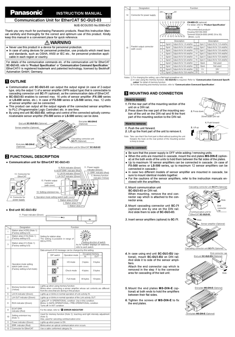
Ferrule (sleeve)
terminal
Release button
(Purchase separately)
Lead wire inlet
Lead wire
Flathead screwdriver
5. Mount the end plates MS-DIN-E (op-
tional) at both ends to hold the ampli-
ers between their at sides.
6. Tighten the screws of MS-DIN-E to
x the end plates.
How to remove sensor ampliers
1. Press down release lever of SC-71
and pull out the sensor amplifier.
(Note)
In state of cascading, the sensor am-
pliers can be pulled out.
Note: Be sure that the release lever is broken without
pressing down release lever when pulling out the
sensor ampliers.
Do not use the cascading connector unit that the
release lever is broken.
How to remove units
1. Loosen screws of MS-DIN-E.
2. Remove MS-DIN-E.
3. Slide
SC-71 to disconnect the connection.
4. Remove each units.
5MEMORY FUNCTION
●Memory function can be used only when connecting the optically communicationable
sensor amplier (FX-500 series or LS-500 series) and the end unit SC-GU3-EU
(op-
tional).
● This function enables to store the set contents of connected sensor ampliers in
the communication unit SC-GU3-02 by each channel and send the stored con-
tents to newly connected sensor ampliers by each channel.
When storing set contents
1.
Turn ON the power in the condition that the sensor ampliers are connected to
SC-GU3-02.
2. Storing starts after pressing the setting extension key down for approx. 2 sec.
3. When the storing to
SC-GU3-02
is complete, the memory function indicator
(yellow) lights up.
Note: To cancel the memory function, press the setting extension key for approx. 2 sec. again.
When sending the stored set contents
1. Turn OFF the power of
SC-GU3-02.
2. Remove the sensor ampliers that are connected to
SC-GU3-02
and mount
new sensor ampliers to which the set contents are transmitted to SC-71.
3. When turning ON the power of
SC-GU3-02
, memory function indicator (yellow)
blinks.
However, if the setting contents of the connected sensor ampliers are same
as the one that are stored in
SC-GU3-02
, it lights up.
4. When pressing the setting extension key, transmission of the set contents is
started.
5. When the transmission is complete, the memory function indicator (yellow)
turns to light up from blinking.
6CONNECTION WITH UPPER COMMUNICATION
● Make sure that the power is OFF while wiring.
● Be sure to use the specied communication cable.
● The communication distance should be within the specication.
●When connecting to the terminal block, in-
sert a solid wire or twisted wire (lead wire)
with a ferrule (sleeve) terminal (please ar-
range separately) into the hole as shown in
the figure at the right. The wire is locked
when it is properly inserted. However, do not
to pull the wire with excessive force, as this
can cause a cable break.
●When connecting the twisted wire (lead wire)
without a ferrule (sleeve), insert the wire to
the innermost of the connecting hole while
pressing the release button.
●When releasing the solid wire or the twisted
wire (lead wire), pull the wire while pressing
the release button.
●The following solid wire and twisted wire (lead wire) 0.2 to 2.5mm2(AWG 24 to
12) are recommended.
● Use the DeviceNet specied cable. Make sure to ground the shielded cable.
●When mounting the DeviceNet connector, the tightening torque should be
0.2N·m or less.
Pull out Release lever
End plate MS-DIN-E (Optional)
End plate MS-DIN-E (Optional)
7ERROR INDICATOR
In case of errors, attempt the following measures.
Indicator State Cause Corrective action
Error
indicator
(Red)
Blinks
Optical communication does not work
properly.
Check the connection status of the connected sensor
ampliers or sensor unit and connection of end unit.
Check the optical communication command and the
transmitted data. For details, refer to “Product
specication” or “Communication command speci-
cation.”
By pressing down the setting extension key, error
indicator turns o.
MS
indicator
(Green/Red)
Green
blinks State of “Stand by” Check the connection of communication cable and
termination resistor.
Red
lights up
SC-GU3-02 may be broken. Contact our sales oce.
Red
blinks
Communication setting of SC-GU3-02
has problem.
Check address setting, baud rate and operation
mode setting switch.
After the conrmation, restart SC-GU3-02.
NS
indicator
(Green/Red)
Green
blinks
Network wiring is done properly however
cannot communicate with master unit
Be sure SC-GU3-02 is registered in the master unit.
Red
lights up
Address is overlapped. Be sure that the address is not overlapped with
other unit.
Red
blinks
One or more connection is in state of
communication time out.
Check network wiring and seting.
After the conrmation above, restart SC-GU3-02 again.
8SPECIFICATIONS
●Communication unit for DeviceNet SC-GU3-02
Designation Communication unit for DeviceNet
Model No. SC-GU3-02
Applicable sensor amplier
Sensor amplier (NPN output type) that can connect the cascading connector SC-71 (optional)
Number of
connectable units Max. 16 units per 1 of SC-GU3-02 (Max. 12 units for FX-500 series or LS-500 series)
Supply voltage 11~25V DC Ripple P-P10% or less
Current consumption 80mA or less at 24V source voltage (excluding connected sensor ampliers, etc.)
Allowable passing current
(Note)
Total: 2A or less
Communication method DeviceNet compliant
Compliant functions I/O message (Poll), Explicit message
Baud rate 125kbps, 250kbps, 500kbps (set by SC-GU3-02)
Address setting 0 to 63 (64 or more is error)
Ambient temperature
-10 to +55ºC (If 4 to 7 units are connected in cascade: -10 to +50ºC, if 8 to 16 units are
connected in cascade: -10 to +45ºC) (No dew condensation or icing allowed), Storage: -20 to
+70ºC
Ambient humidity 35 to 85% RH, Storage: 35 to 85% RH
Material Enclosure: Polycarbonate
Weight Net wight Approx. 75g
Note: It is the value that can supply to SC-GU3-02 or the sensor units connected to SC-GU3-02, etc.
●End unit SC-GU3-EU
Designation End unit
Model No. SC-GU3-EU
Applicable sensor amplier
• Communication unit for DeviceNet SC-GU3-02
• Between SC-GU3-01 to SC-GU3-EU: FX-500 series, LS-400 series etc.
Number of
connectable units 1 unit for 1 of SC-GU3-02
Supply voltage 11 to 25V DC % Ripple P-P10% or less
Current consumption 25mA or less
Ambient temperature
-10 to +55ºC (If 4 to 7 units are connected in cascade: -10 to +50ºC, if 8 to 16 units are
connected in cascade: -10 to +45ºC) (No dew condensation or icing allowed), Storage: -20 to
+70ºC
Ambient humidity 35 to 85% RH, Storage: 35 to 85% RH
Material Enclosure: Polycarbonate
Weight Approx. 20g
●Cascading connector unit SC-71
Designation Cascading connector unit
Model No. SC-71
Applicable sensor amplier
• Communication unit for DeviceNet SC-GU3-02
• Communication end unit SC-GU3-EU
• Between SC-GU3-02 to SC-GU3-EU: FX-500 series, LS-400 series etc.
Number of
connectable units Max. 16 units per 1 of SC-GU3-02 (Max. 12 units for FX-500 series or LS-500 series)
Ambient temperature
-10 to +55ºC (If 4 to 7 units are connected in cascade: -10 to +50ºC, if 8 to 16 units are
connected in cascade: -10 to +45ºC) (No dew condensation or icing allowed), Storage: -20 to
+70ºC
Ambient humidity 35 to 85% RH, Storage: 35 to 85% RH
Material Enclosure: Polycarbonate , Metal plate: aluminum
Weight Approx. 10g
9CAUTIONS
●This product has been developed / produced for industrial use only.
● Make sure that the power supply is OFF while wiring and adding the units.
●Take care that wrong wiring will damage the product.
●Verify that the supply voltage variation is within the rating including the sensor
amplier.
●In case noise generating equipment (switching regulator, inverter motor, etc.)
is used in the vicinity of this product, connect the frame ground (F.G.) terminal
of the equipment to an actual ground.
●Do not use during the initial transient time (2 sec.) after the power supply is
switched on. In case using memory function or not using a SC-GU3-EU, be
sure that transient time after the power supply is switched on becomes longer
●This product is suitable for indoor use only.
●This product cannot be used in an environment containing inflammable or
explosive gases.
●Never disassemble or modify the product.
●For the wiring of this product, refer to “DeviceNet Installation Manual” by ODVA
●Any protective devices or safety circuits against system malfunction should be
designed to be external to the system.
https://panasonic.net/id/pidsx/global
Overseas Sales Division (Head Oce)
2431-1 Ushiyama-cho, Kasugai-shi, Aichi, 486-0901, Japan
Phone: +81-568-33-7861 FAX: +81-568-33-8591
For sales network, please visit our website.
PRINTED IN JAPAN © Panasonic Industrial Devices SUNX Co., Ltd. 2019
