manuals.online logo
Brands
  1. Home
  2. •
  3. Brands
  4. •
  5. Honeywell
  6. •
  7. Control Unit
  8. •
  9. Honeywell ADEMCO 5800RL User manual

Honeywell ADEMCO 5800RL User manual

Other Honeywell Control Unit manuals

Honeywell Exi-/MaxLED T2 User manual

Honeywell

Honeywell Exi-/MaxLED T2 User manual

Honeywell NOTIFIER NZM-100 User manual

Honeywell

Honeywell NOTIFIER NZM-100 User manual

Honeywell Prestige THX9421R02 User manual

Honeywell

Honeywell Prestige THX9421R02 User manual

Honeywell 7800 SERIES User manual

Honeywell

Honeywell 7800 SERIES User manual

Honeywell ADEMCO 4190SN Assembly instructions

Honeywell

Honeywell ADEMCO 4190SN Assembly instructions

Honeywell S4560 User manual

Honeywell

Honeywell S4560 User manual

Honeywell Krom Schroder BCU 580 Manual

Honeywell

Honeywell Krom Schroder BCU 580 Manual

Honeywell EXCEL 5000 OPEN ZAPP User manual

Honeywell

Honeywell EXCEL 5000 OPEN ZAPP User manual

Honeywell V305 Series User manual

Honeywell

Honeywell V305 Series User manual

Honeywell NOTIFIER FCM-1 User manual

Honeywell

Honeywell NOTIFIER FCM-1 User manual

Honeywell Resideo ADEMCO 4101SN V-Plex Assembly instructions

Honeywell

Honeywell Resideo ADEMCO 4101SN V-Plex Assembly instructions

Honeywell TS131 User manual

Honeywell

Honeywell TS131 User manual

Honeywell BA295I User manual

Honeywell

Honeywell BA295I User manual

Honeywell NK298S User manual

Honeywell

Honeywell NK298S User manual

Honeywell RV280 User manual

Honeywell

Honeywell RV280 User manual

Honeywell VR8200A User manual

Honeywell

Honeywell VR8200A User manual

Honeywell Notifier XP6-C User manual

Honeywell

Honeywell Notifier XP6-C User manual

Honeywell VR8204 Series User manual

Honeywell

Honeywell VR8204 Series User manual

Honeywell NOTIFIER SCS Series Specification sheet

Honeywell

Honeywell NOTIFIER SCS Series Specification sheet

Honeywell 3GL User manual

Honeywell

Honeywell 3GL User manual

Honeywell Elster Jeavons S200 User manual

Honeywell

Honeywell Elster Jeavons S200 User manual

Honeywell D16 User manual

Honeywell

Honeywell D16 User manual

Honeywell Kromschroder TC 1 User manual

Honeywell

Honeywell Kromschroder TC 1 User manual

Honeywell V1810 Alwa-Kombi-4 User manual

Honeywell

Honeywell V1810 Alwa-Kombi-4 User manual

Popular Control Unit manuals by other brands

Festo Compact Performance CP-FB6-E Brief description

Festo

Festo Compact Performance CP-FB6-E Brief description

Elo TouchSystems DMS-SA19P-EXTME Quick installation guide

Elo TouchSystems

Elo TouchSystems DMS-SA19P-EXTME Quick installation guide

JS Automation MPC3034A user manual

JS Automation

JS Automation MPC3034A user manual

JAUDT SW GII 6406 Series Translation of the original operating instructions

JAUDT

JAUDT SW GII 6406 Series Translation of the original operating instructions

Spektrum Air Module System manual

Spektrum

Spektrum Air Module System manual

BOC Edwards Q Series instruction manual

BOC Edwards

BOC Edwards Q Series instruction manual

KHADAS BT Magic quick start

KHADAS

KHADAS BT Magic quick start

Etherma eNEXHO-IL Assembly and operating instructions

Etherma

Etherma eNEXHO-IL Assembly and operating instructions

PMFoundations Attenuverter Assembly guide

PMFoundations

PMFoundations Attenuverter Assembly guide

GEA VARIVENT Operating	 instruction

GEA

GEA VARIVENT Operating instruction

Walther Systemtechnik VMS-05 Assembly instructions

Walther Systemtechnik

Walther Systemtechnik VMS-05 Assembly instructions

Altronix LINQ8PD Installation and programming manual

Altronix

Altronix LINQ8PD Installation and programming manual

Eaton Powerware Series user guide

Eaton

Eaton Powerware Series user guide

WAGO 750-407/040-000 manual

WAGO

WAGO 750-407/040-000 manual

Sony CCU-590 Operation manual

Sony

Sony CCU-590 Operation manual

Graco 25D614 instructions

Graco

Graco 25D614 instructions

Task Force Tips YE-RF-900 Instructions for installation, safe operation and maintenance

Task Force Tips

Task Force Tips YE-RF-900 Instructions for installation, safe operation and maintenance

Shini SPV-U Series manual

Shini

Shini SPV-U Series manual

manuals.online logo
manuals.online logoBrands
  • About & Mission
  • Contact us
  • Privacy Policy
  • Terms and Conditions

Copyright 2025 Manuals.Online. All Rights Reserved.

ADEMCO 5800RL Wireless Relay Module – Installation Instructions
INTRODUCTION
The ADEMCO 5800RL is a Wireless Relay Module that
enables use of remote sounders and/or remote arm/disarm
indicators using two relays activated by wireless signals from
a LYNX control. The 5800RL can also send tamper and
supervision signals to the LYNX if so programmed. The
5800RL is compatible with LYNX Plus controls having
software versions 9.0 or higher and LYNX Touch controls.
Refer to the LYNX control installation and setup guide for
software compatibility and zone programming information.
5800RL
RELAY MODULE
TAMPER AND
SUPERVISION
SIGNALS SENT
TO CONTROL
MODULE'S TWO
RELAYS ARE
ACTIVATED BY
SYSTEM
CONDITIONS
5800RL-004-V1
BYPASS
NODELAY
RECORD
TEST
FUNCTION
STATUS
VOLUME PLAY
CODE
LIGHTSON
LIGHTSOFF CHIME
ESCAPE
ADD
DELETE
SELECT
OFF STAY
1 32
AWAY AUX
4 65
ARMED READY
79
8
0
Figure 1. Lynx Interface Diagram
MOUNTING LOCATION GUIDELINES
Use the following guidelines when selecting a mounting
location for the 5800RL Relay Module (see Figure 2):
•Mount the 5800RL in a high location for best wireless
reception.
•Do not mount the 5800RL on or near metal objects. This
decreases range and/or blocks wireless transmissions.
•Locate the 5800RL at least 10 feet from any remote
keypad to avoid interference from the microprocessors in
those units.
•To avoid voltage loss that occurs on long power lines,
mount the external power supply unit in close proximity to
the 5800RL.
Mounting, Wiring, and Setup
IMPORTANT: Before permanently mounting the 5800RL,
perform the setup procedure described in the Setting Up
the 5800RL section.
1. Remove the 5800RL's cover from the base (using a small
flat head screwdriver, insert screwdriver’s tip in slot at top
of the cover and twist).
2. Using the 5800RL base as a template, position in the
desired location and mark the two mounting holes. See
Figure 2 for mounting hole locations.
3. Attach the 5800RL base using the fasteners supplied.
Screws and plastic anchors are suitable for a typical
installation, but you may use any two fasteners that
secure the base firmly to the mounting surface.
NOTE: This product uses latching relays, which retain their
open/closed position even when power is disconnected. Due
to shocks or vibration during shipment and installation, the
out-of-box state of these relays may be either open or closed.
When power is first applied, the relay will be set to its correct
initial state. Please bear this in mind during installation; it is
strongly recommended that you wire this module and apply
power to it before energizing any external circuit controlled by
the latching relay.
4. Connect relay and power wiring to the 5800RL’s terminals.
Refer to Figure 3 for a typical relay application.
The 5800RL can be powered from either an AC transformer
or DC power supply external power source connected to
terminals 7 and 8 (see Figure 3).
Power source ratings and connections are as follows:
Type
Rating
Connected to…
Source Example
AC 9VAC, 15VA terminals 7 and 8 Ademco 1332
DC 12VDC, 100mA terminals 7 and 8
or plugged into
power connector.
AD12612
NOTE: Use of power sources with higher or lower voltages
may result in damage or failure to operate properly. Non-
ADEMCO power supplies may have connectors installed.
Remove these connectors prior to attempting to connect
power supply to 5800RL.
TAMPER
SWITCH
2 - NO
3 - COM
4 - NC
5 - NO
6 - COM
7 - AC OR DC (+) IN
1 - NC
8 - AC OR DC ( ) IN
RELAY A
RELAY B
LED
(RED)
LED
(YELLOW)
LED
(GREEN)
RF INTERFERENCE
LED (RED)
ANTENNA 2
ANTENNA 1
DIP
SWITCH
MOUNTING
HOLE
MOUNTING
HOLE
123456
ON
OFF
Figure 2. 5800RL Diagram
2 - NO
3 - COM
4 - NC
5 - NO
6 - COM
7 - AC OR DC (+) IN
1 - NC
8 - AC OR DC ( ) IN
RELAY A
RELAY B
5800RL-005-V0
ANTENNA 2
SOUNDER
ANTENNA 1
123456
ON
OFF
ADEMCO AD12612
AUX PWR SUPPLY
(12 VDC)
AC
IN
+
_
DC
OUT
1361
+_
RED
BLACK
POWER SUPPLY
BACKUP
BATTERY 12VDC
+
PWR SUPPLY
XFMR
16.5VAC
Figure 3. Typical Sounder Wiring Installation
Setting Up the 5800RL
Refer to RELAY and LED Operation section and DIP Switch
(Figure 4) in order to set up the 5800RL as follows:
5. Set DIP switches 3-6 (Figure 4) to the appropriate House
ID (1-31). Make sure the House ID set by the DIP
switches matches that entered in the LYNX control.
6. If module supervision and/or tamper protection is desired,
program the 5800RL’s tamper/supervisory loop (1) as a
zone and enroll its serial number.
Note the following when enrolling:
Zone Type = 5 (trouble by day/alarm by night)
Input Type = 3 (RF)
Loop Number = 1
7. Position the wiring in the exit slot and reinstall the
5800RL’s cover on the base.
Test the 5800RL module with the rest of the system.
HOUSE
ID
DIP SWITCH POSITIONS
HOUSE
ID
DIP SWITCH POSITIONS
2 3 4 5 6 2 3 4 5 6
0
-
- - - - 16
ON
- - - -
1
- - - - ON
17
ON - - - ON
2
- - - ON -
18
ON - - ON -
3
- - - ON ON
19
ON - - ON ON
4
- - ON - -
20
ON - ON - -
5
- - ON - ON
21
ON - ON - ON
6
- - ON ON -
22
ON - ON ON -
7
- - ON ON ON
23
ON - ON ON ON
8
- ON - - -
24
ON ON - - -
9
- ON - - ON
25
ON ON - - ON
10
- ON - ON -
26
ON ON - ON -
11
- ON - ON ON
27
ON ON - ON ON
12
- ON ON - -
28
ON ON ON - -
13
- ON ON - ON
29
ON ON ON - ON
14
- ON ON ON -
30
ON ON ON ON -
15
- ON ON ON ON
31
ON ON ON ON ON
“ – “ indicates “OFF”
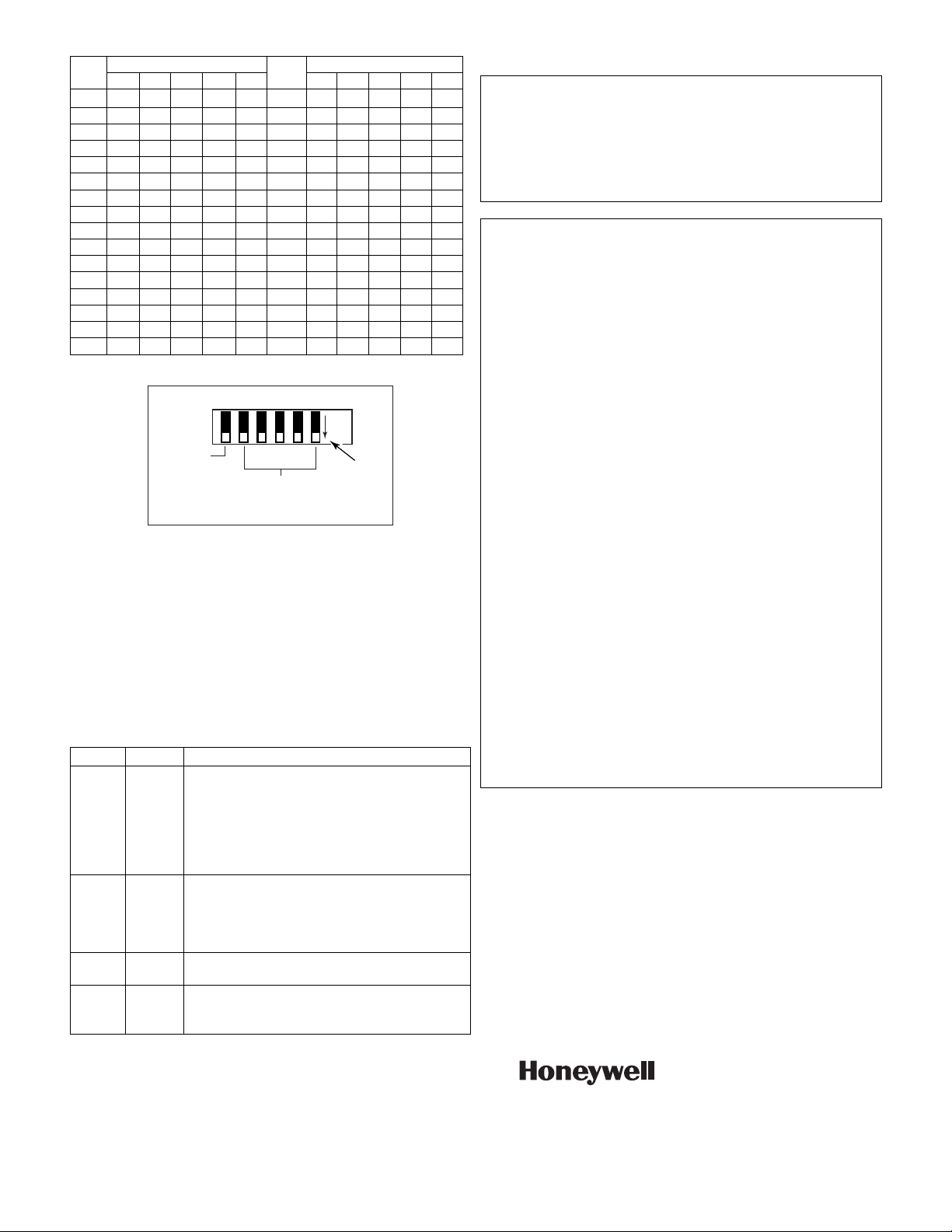
2 3 4 5 61
2-6 SETS HOUSE ID
SW-1
NOT USED
5800RL DIP Switch 5800RF-003-V0
OFF POSITION
INDICATOR
SV6
7L
Figure 4. DIP Switch Settings
RELAY and LED Operation
The 5800RL contains two relays (Figure 2) (SPDT, rated 2A.
28VAC/VDC) that may be used to activate remote sounders
and/or remote arm/disarm indicators. There are three LEDs
(green, yellow, red) located above the DIP switch and one
LED (red) located approximately in the center of the pc board.
The LEDs located above the DIP switch, indicate power and
relay activity. Refer to Figure 2 on the previous page. The RF
Interference LED monitors local radio frequency interference.
If this LED is continuously lit, the 5800RL should be
relocated.
Relay LED Activates Upon…
A Yellow Alarm conditions as follows:
Steady ON = burglary alarm (NO contact
connects to COM)
Temporal ON = fire alarm (NO contact connects
temporal to COM)
OFF = no alarms present (NC contact connects
to COM)
B Red System armed/disarmed as follows:
ON = system armed Away, Stay, or Instant (NO
contact connect to COM)
OFF = system disarmed (NC contact connects to
COM)
N/A Green Normally on (lighted) when power is applied.
Flickering indicates RF is being processed.
N/A RF
Inter-
ference
Lights when RF activity is present.
If this LED is continuously lit, relocate the
5800RL module.
SPECIFICATIONS
Dimensions: 2-3/4”W x 4-15/16”H x 1-1/16”D
(70mm x 125mm x 27mm)
Voltage: 12VDC 100mA or
9VAC, 15VA (use ADEMCO 1332 or equivalent)
Current: 100mA
Relay: Two relays, each with choice of normally open (NO)
or normally closed (NC) operation.
Operating Temperature: 0 - 50°
C / 32 - 122°
F
Federal Communications Commission (FCC) Part 15
The user shall not make any changes or modifications to the equipment unless
authorized by the Installation Instructions or User's Manual. Unauthorized
changes or modifications could void the user's authority to operate the
equipment.
CLASS B DIGITAL DEVICE STATEMENT
This equipment has been tested to FCC requirements and has been found
acceptable for use. The FCC requires the following statement for your
information:
This equipment generates and uses radio frequency energy and if not installed
and used properly, that is, in strict accordance with the manufacturer's
instructions, may cause interference to radio and television reception. It has
been type tested and found to comply with the limits for a Class B computing
device in accordance with the specifications in Part 15 of FCC Rules, which are
designed to provide reasonable protection against such interference in a
residential installation. However, there is no guarantee that interference will not
occur in a particular installation. If this equipment does cause interference to
radio or television reception, which can be determined by turning the equipment
off and on, the user is encouraged to try to correct the interference by one or
more of the following measures:
• If using an indoor antenna, have a quality outdoor antenna installed.
• Reorient the receiving antenna until interference is reduced or eliminated.
• Move the radio or television receiver away from the receiver/control.
• Move the antenna leads away from any wire runs to the receiver/control.
• Plug the receiver/control into a different outlet so that it and the radio or
television receiver are on different branch circuits.
• Consult the dealer or an experienced radio/TV technician for help.
INDUSTRY CANADA CLASS B STATEMENT
This Class B digital apparatus complies with Canadian ICES-003.
Cet appareil numérique de la classe B est conforme à la norme NMB-003 du
Canada.
FCC/IC STATEMENT
This device complies with Part 15 of the FCC rules and RSS 210 of Industry
Canada. Operation is subject to the following two conditions: (1) This device
may not cause harmful interference, and (2) This device must accept any
interference received, including interference that may cause undesired
operation.
Cet appareil est conforme à la partie 15 des règles de la FCC & de RSS 210
des Industries Canada. Son fonctionnement est soumis aux conditions
suivantes: (1) Cet appareil ne doit pas causer d' interférences nuisibles. (2) Cet
appareil doit accepter toute interférence reçue y compris les interférences
causant une réception indésirable.
ÊK37906Š
K3790 6/07 Rev. C
2 Corporate Center Drive, Melville, NY 11747
Copyright © 2007 Honeywell International Inc.
www.honeywell.com/security