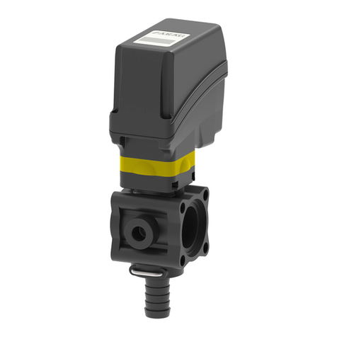
ARAG 463 Series Quick start guide

463 - 464 - 465 - 471 SERIES
MANUAL CONTROL UNIT
FOR CROP-SPRAYING APPLICATIONS
02
INSTALLATION, USE AND MAINTENANCE

This manual is an integral part of the equipment to which it refers and must accompany the equipment in
case of sale or change of ownership. Keep it for future reference; ARAG reserves the right to modify the
specications and instructions regarding the product at any time and without prior notice.
CONTENTS
• Legend symbols .............................................................................................................................. 2
1 Product description............................................................................................................................. 3
1.1 Intended use ............................................................................................................................. 3
2 Functioning of the product.................................................................................................................. 4
2.1 Composition of the manual control units...................................................................................... 4
2.1.1 Manual control units with 471 SERIES main control valve ......................................................... 4
2.1.2 Manual control units with 464 SERIES main control valve ......................................................... 5
2.2 Functions of components .......................................................................................................... 6
3 Installation .......................................................................................................................................... 7
3.1 Safety regulations...................................................................................................................... 7
3.2 Installing and connecting the unit................................................................................................ 8
3.3 Connecting up the system.......................................................................................................... 9
4 Settings before use ............................................................................................................................11
4.1 Adjustments of the manual unit prior to operation .......................................................................11
4.2 Adjustment of maximum operating pressure (only applicable for units with proportional ...................
valve) 13
5 Use .................................................................................................................................................... 14
5.1 Calibration of operating pressure .............................................................................................. 14
5.2 Calibration of compensation cocks (calibrated backflows) .......................................................... 15
6 Maintenance / diagnostics / repairs .................................................................................................. 16
6.1 Cleaning the manual control units............................................................................................. 16
6.2 Cleaning the filters................................................................................................................... 17
6.2.1 Manual cleaning ................................................................................................................... 17
6.2.2 Automatic cleaning of self-cleaning filters............................................................................... 18
6.3 Troubleshooting ....................................................................................................................... 21
6.3.1 Troubleshooting - Units with constant pressure....................................................................... 21
6.3.2 Troubleshooting - Units with proportional valve ....................................................................... 22
7 Technical data ................................................................................................................................... 23
7.1 Correspondence between valve parts and maximum valve pressure .......................................... 23
7.2 Correspondence between valve type and flowrate ..................................................................... 24
7.2.1 Legend symbols ................................................................................................................... 24
7.2.2 Main control valve................................................................................................................. 24
7.2.3 Maximum pressure valve....................................................................................................... 24
7.2.4 Proportional valve ................................................................................................................. 25
7.2.5 Boom section valve............................................................................................................... 25
8 Disposal at the end of service........................................................................................................... 25
9 Guarantee terms................................................................................................................................ 26
10 Conformity Declaration ..................................................................................................................... 27
• LEGEND SYMBOLS
=Generic danger
=Warning
3
1 PRODUCT DESCRIPTION
ARAG manual control units for crop spraying are composed of individual, manual type modular valves.
When installed on crop spraying machines, they ensure regular distribution of pesticides.
This booklet describes all the various parts that may be included in the unit. Some
of these parts may not be included in your unit. Likewise, given the modularity of the
product, some types of parts may not be assembled together but are only alternati-
ves for others.
The illustrations in this booklet are, therefore, provided only as indications. For detai-
led information, please refer to the description of the part in question and not of the
unit in general.
ARAG is not liable for any damage caused directly or indirectly by the type of uids
used for spraying by its control units.
The operator has full liability for the use of these products and therefore must verify
the safety regulations indicated on the package by the manufacturer of the liquid
and must wear suitable protective clothing (gloves, overall, footwear, helmet, etc.) as
required by law.
ARAG is therefore not liable for any damage or injury to persons, animals or things
as a result of the incorrect use of the products employed, without protection or con-
trary to recommendations.
1.1 Intended use
This device is designed to work on agricultural machinery for crop spraying
applications.
The machine is designed and built in compliance with EN ISO 14982 standard
(Electromagnetic compatibility - Forestry and farming machines), harmonized with
2014/30/UE Directive.

4
2 FUNCTIONING OF THE PRODUCT
2.1 Composition of the manual control units
The pictures of the control units in the following pages must be considered a mere
example and might not correspond to the conguration of your own unit.
2.1.1 Manual control units with 471 SERIES main control valve
F i g . 1
1Main control lever
2Maximum pressure valve
3Proportional valve
4Filter
5Boom section valves
6Adjustable compensation cocks (calibrated backows)
7Pressure gauge adapter
IN Intake of liquid for spraying
OUT A Discharge for maximum pressure valve
OUT B Discharge for calibrated backows
OUT C Discharge for proportional valve
OUT D Discharge for self-cleaning lter
U1...U5 Boom section delivery
The Main control lever (1) + Maximum pressure valve (2) subassembly corresponds to the
471 SERIES main control valve.

5
2.1.2 Manual control units with 464 SERIES main control valve
F i g . 2
1Main control lever
2Maximum pressure valve
3Proportional valve
4Filter
5Boom section valves
6Adjustable compensation cocks (calibrated backows)
7Pressure gauge adapter
IN Intake of liquid for spraying
OUT A Discharge for maximum pressure valve
OUT B Discharge for calibrated backows
OUT C Discharge for proportional valve
OUT D Discharge for self-cleaning lter
U1...U5 Boom section delivery
The Main control lever (1) + Maximum pressure valve (2) subassembly corresponds to the
464 SERIES main control valve.

6
2.2 Functions of components
1Main control lever
Controls the direction of the liquid through the system.
Lever down = liquid sent directly to the circuit for application
Lever up = liquid sent to the tank; the suction system, if present, starts functioning.
2Maximum pressure valve
Eliminates the excess liquid when the set pressure level is reached.
Can be adjusted manually using the appropriate knob; the knob has a different colour according
to the maximum pressure for the valve (refer to section 7.1 - Correspondence between valve parts
and maximum valve pressure for information on pressure values).
3Proportional valve
This is adjusted to control spraying pressure: when the vehicle progress speed changes during
spraying, the volume of the liquid distributed per surface unit (litres/ hectare) remains stable.
The increase or reduction in delivery is proportional to the number of revs of the engine with a
tolerance of +- 20%.
Can be adjusted manually using the appropriate yellow knob.
4Filter
Protects nozzles from dirt, which would eventually reduce their performance.
With self-cleaning lters, there is less need for frequent cleaning of the cartridge inside the lter.
5Boom section valves
Opens/closes the corresponding boom section. For valves with calibrated backows, the closed valve
position coincides with that for the discharge of the corresponding compensation cock.
6Adjustable compensation cocks (calibrated backows)
These are adjusted so the level of spraying pressure remains steady when one or more sections
of the boom are closed.
7Pressure gauge adapter (pressure gauge optional)
Adapter for pressure gauge connection (the pressure gauge indicates the working pressure when
the main control valve is open).
Details of operation are found below. Please refer to Section 4 - Actions prior to use
and 5 - Use for descriptions of the adjustment of individual parts.

7
3 INSTALLATION
3.1 Safety regulations
• Do not install the control unit inside the driver’s cab.
• Install the unit so that the valve levers are accessible for control but at a safe di-
stance from the position of the operator.
• The intake owrate for the unit must be less than maximum ow rate envisaged for
the main control valve.
• The parts and the hoses that are installed on the main pressure line (delivery line)
must be capable of withstanding greater levels of pressure than that of the maximum
pressure valve (refer to Section 7.2.3 - Maximum pressure valve).
• Commission the discharge system according to the maximum delivery ow rate for
the pump. Also install hose whose nominal operating pressure is greater than that of
the discharge: any bottlenecks in the discharge system could cause abnormally high
pressure levels.
• Make sure the hoses used are suitable for the diameters of the chosen hose tails.
• Use systems to secure the hoses that are suitable for the hoses in question.
It is recommended to install a pressure-relief device (Series 459 on general ARAG
catalogue) on the pump to avoid risks caused by a unit malfunction.
This device does not replace a further safety valve, but it can limit unit damages in
case of sudden over-pressures.
Contact skilled personnel for any intervention requiring modications to the congu-
ration of the hydraulic connections.
ARAG is not liable for any damage to equipment or injury to persons, animals or
things caused by incorrect or unsuitable connection of the unit.
Likewise, ARAG is not liable for any damage caused directly or indirectly to
equipment or machinery, or injury to persons, animals or things caused by unsuita-
ble or unt hoses, cable grips, wraps or other accessory.
All forms of warranty are rendered null and void in case of damage to the unit caused
by the above.

8
3.2 Installing and connecting the unit
Install the control unit and secure it using the appropriate holes located on the brackets, as shown
in Fig. 3.
Fi g . 3
We recommend following the standard array for assembly for optimum performance of the unit, as
shown in Fig. 4.
Fi g . 4
Fixing holes

9
3.3 Connecting up the system
Connect the hoses in the system according to the layout shown below.
Take care:
- Not to connect backow hoses in the lower part of the tank with the intention of using them as
hydraulic stirrers; only place them in the upper part so the liquid drops down by gravity, as shown
in Fig. 5.
Fi g . 5
Fi g . 6
RIGHT
WRONG

10
- Make a separate connection of the backow of the valves with the tank, as shown in Fig. 7.
CORRETTO
Fi g . 7
ERRATO
Fi g . 8
RIGHT
WRONG

11
4 SETTINGS BEFORE USE
ONLY use clean water for any intervention or adjustment without any chemical addi-
tives.
All instructions for installation, adjustment and operation ALWAYS refer to the stan-
dard position for the installation of the unit (refer to Fig. 4).
4.1 Adjustments of the manual unit prior to operation
a) Fit the pressure gauge on the adap-
ter, screw it down completely without
tightening it excessively.
Use ARAG pressure gauges with
1/4" M coupling and a suitable end sca-
le for the maximum operating pressure.
b) Put the main valve in the discharging
position by raising its lever
("OFF" position).
c) Turn the knob anticlockwise to com-
pletely open the hand wheel
of the maximum pressure valve.
CONTINUES

12
d) Turn the yellow knob anticlockwise
and completely open the proportional
valve.
e) Close all the section valves by lowe-
ring their levers ("OFF" position).
f) Open all the compensation cocks by
turning their knobs anticlockwise.
g) Turn the knob clockwise and
completely close the discharge to the
self-cleaning lter.
End of the procedure for "Adjustments of the manual unit prior to operation"

13
4.2 Adjustment of maximum operating pressure (only applicable for units with proportional
valve)
Should either of the following be noted during operation:
• pressure above the maximum limit for the system and safety valve;
• abnormal leaks of liquid;
- stop work, switch the pump off and check that the installation and preliminary pro-
cedures have been completed correctly.
a) Start pump operation.
b) Lower the lever to open the main
valve ("ON" position): the liquid will now
be introduced into the unit and the pres-
sure gauge will indicate its pressure.
c) Gradually increase the number of
revs of the pump until the maximum
operating level is reached.
d) Close the proportional valve comple-
tely by turning its knob clockwise.
e) Close all the compensation cocks by
turning their knobs clockwise.
f) Adjust the maximum pressure valve
by turning its knob clockwise until the
pressure of the valve is about 20%
above the unit’s maximum operating
pressure.
The pressure levels are indicated on
the pressure gauge.

14
5 USE
5.1 Calibration of operating pressure
a) Select the type of nozzle and the
relative operating pressure according
to the litres/hectare (l/ha) to be sprayed
and the speed of progress.
b) the machine off, start the pump and
take it to its operating level.
c) Open the main valve by lowering its
lever ("ON" position).
d) Open all the section valves by raising their levers ("ON" position).
e) Now take the unit pressure to the required level for spraying: there are two ways to perform this
adjustment:
• Constant pressure units:
This kind of unit does not have a pro-
portional valve, therefore the calibration
of the operating pressure is carried out
by the maximum pressure valve.
The adjustment is made by turning the
knob on the maximum pressure valve
until operating pressure is obtained:
- Turn clockwise to increase pressure;
- Turn anticlockwise to decrease
pressure.
• Units with proportional valve:
The calibration of the operating pressure is carried out by the proportional
valve.
The adjustment is made by turning the yellow knob on the valve until the
required operating pressure is obtained:
- Turn clockwise to increase pressure;
- Turn anticlockwise to decrease pressure.
In this case, the proportional valve must be used for pressure
adjustment and not the maximum pressure valve since the proportional
valve would not compensate the variations in speed correctly should
the operating pressure be too close to the calibration of the maximum
pressure valve.

15
5.2 Calibration of compensation cocks (calibrated backows)
These cocks safeguard the constant distribution of liquid even in case of operation with one or two
section valves closed.
Calibration must be carried out EACH TIME the type of nozzle is changed.
a) Close a section valve by lowering its
lever ("OFF" position).
b) Adjust the corresponding compen-
sation cock by turning the knob until
the pressure level is restored on the
pressure gauge that was previously set
with all the section valves open.
- Turn clockwise to increase pressure;
- Turn anticlockwise to decrease
pressure.
c) Open and close the section valve (lower the lever to close the valve and
raise it to open it).
Check that the level of pressure indicated on the pressure gauge is constant.
If the level of pressure indicated on the pressure gauge chan-
ges, repeat the steps indicated at point buntil there are no more
variations.
d) Repeat the steps for adjusting pressure for each section valve on the unit.
If the types of nozzle are not changed, the adjustments made
will safeguard a uniform distribution of liquid even when spraying
needs differing levels of operating pressure.

16
6 MAINTENANCE / DIAGNOSTICS / REPAIRS
6.1 Cleaning the manual control units
Protective gloves, goggles and clothing must be worn before starting cleaning.
ARAG is not liable for any damage caused to equipment or injury to persons, ani-
mals or things caused by cleaning with unsuitable products. All forms of warranty
are rendered null and void in case of damage to the unit caused by the above.
- Clean the internal pipes of distributor carefully after each use with clean water or, if necessary,
water with a specic detergent.
Follow the indications in the table below for the frequency of cleaning:
MANUAL CLEANING FREQUENCY
Cleaning with clean water After each use
Filter cleaning After each use
Filter cleaning (self-cleaning type)
Closed cock:
after each use
Open cock:
every month or every 100 hours
Cleaning using a specic detergent Every month or every 100 hours
Tab. 1
- While cleaning the unit, check the seal on the gaskets by checking that there are no unusual
leaks in the unit. Should leaks be noted, remove the unit and send it to your local Service Centre.
- Send the unit to your Service Centre to be checked over and for the valve gaskets to be replaced,
if necessary, once a year or every 500 hours of operation of the system.
Units must be cleaned thoroughly prior to being sent to a Service Centre for control
or repair.
Should the Service Centre receive a dirty unit, it will have the right to refuse delivery
and repair of the same even if it is covered by guarantee.

17
6.2 Cleaning the lters
6.2.1 Manual cleaning
- Clean the lter regularly according to the instructions described below:
a) Protective gloves, goggles and clothing must be
worn.
b) Turn the machine off.
c) Empty any remaining products out of the system.
d) Unscrew the lock ring 1by turning it anticlockwi-
se, slide the lid 3and the cartridge 2.
e) Wash the cartridge 2and the lid 3under running
water.
f) Remove any trapped items under running water.
Do not use compressed air or sharp
objects for cleaning the cartridge.
Take care not to damage the mesh when cleaning the lter. Should you notice any
damage to the mesh, replace the cartridge with a new one.
Refer to the ARAG spare parts catalogue for references for ordering spare parts.

18
6.2.2 Automatic cleaning of self-cleaning lters
Make sure the discharge on the self-cleaning lter is connected to the tank with a
hose before starting cleaning.
There are two methods for cleaning:
• Continual cleaning:
The lter cock is left open so that cleaning is carried out during spraying.
In order to use the lter in this way, you must check that the unit’s intake ow rate is
sufficient to supply both the discharge for the self-cleaning lter in addition to the
unit itself.
This check is carried out as follows:
a) Protective gloves, goggles and clothing must be
worn.
b) Open the self-cleaning discharge completely by
turning the knob anticlockwise.
c) Follow the steps for the adjustment of operating
pressure (refer to section 5.1 - Calibration of opera-
ting pressure).
d) After the calibration of the operating pressure, the
discharge cock can be left open so that the lter is
cleaned automatically during the use of the unit.
Should it prove impossible to reach ope-
rating pressure, the lter cannot be used in this
way and must be cleaned by "regular cleaning".
End of the procedure for continual cleaning of self-cleaning type lters

19
Make sure the discharge on the self-cleaning lter is connected to the tank with a
hose before starting cleaning.
• Regular cleaning:
This procedure can be carried out at the end of each use or any time it is deemed necessary:
a) Protective gloves, goggles and
clothing must be worn.
b) Start the pump and take it to its
operating level.
c) Close all the section valves by lowe-
ring their levers.
d) Open the discharge on the self-
cleaning lter completely by turning the
knob anticlockwise.
e) Open the main valve by lowering its
lever ("ON" position).
f) Allow the system to operate for at
least 2 minutes.
CONTINUES

20
End of the procedure for regular cleaning of self-cleaning type lters
g) Close the main valve by raising its
lever ("OFF" position).
h) Close the discharge on the self-
cleaning lter completely by turning the
knob clockwise.
Other manuals for 463 Series
1
This manual suits for next models
3
Table of contents
Other ARAG Control Unit manuals

ARAG
ARAG 853 Series Quick start guide

ARAG
ARAG IBX100 4679004 User manual

ARAG
ARAG IBX100 4679004 Quick start guide

ARAG
ARAG IBX100 4679004 Installation and operating instructions

ARAG
ARAG 453 Series User guide

ARAG
ARAG VISIO BLC Installation and operating instructions

ARAG
ARAG IBX100 4679004 Quick start guide

ARAG
ARAG 863T Series Quick start guide

ARAG
ARAG IBX100 4679004 Quick start guide

ARAG
ARAG IBX100 4679004 Specification sheet