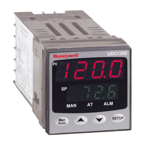
Honeywell ML8824-BV Series User manual
Other Honeywell Controllers manuals
Honeywell
Honeywell Ex-Or MLS Installation and operation manual
Honeywell
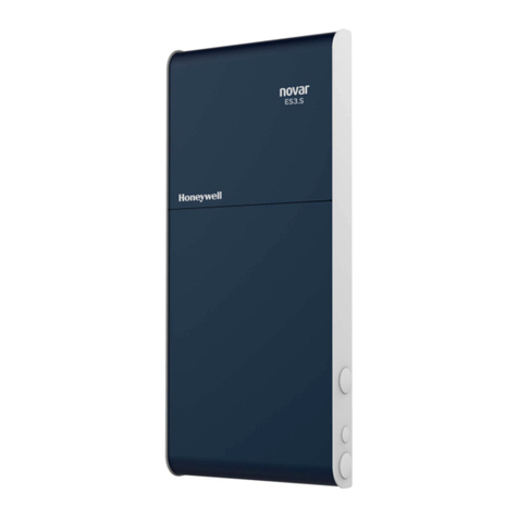
Honeywell Novar ES3.S Programming manual
Honeywell
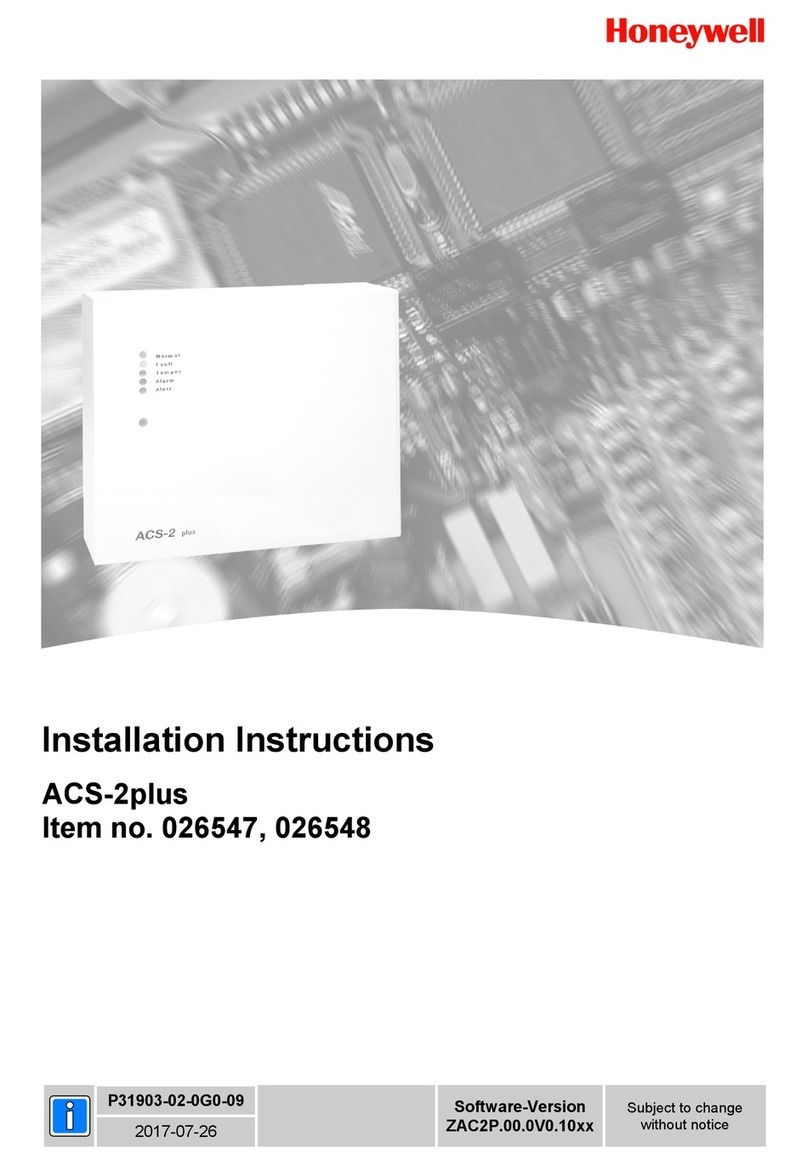
Honeywell ACS-2plus User manual
Honeywell
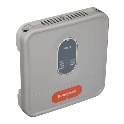
Honeywell TrueZONE HZ311 User manual

Honeywell
Honeywell MIWI350 Operating instructions
Honeywell
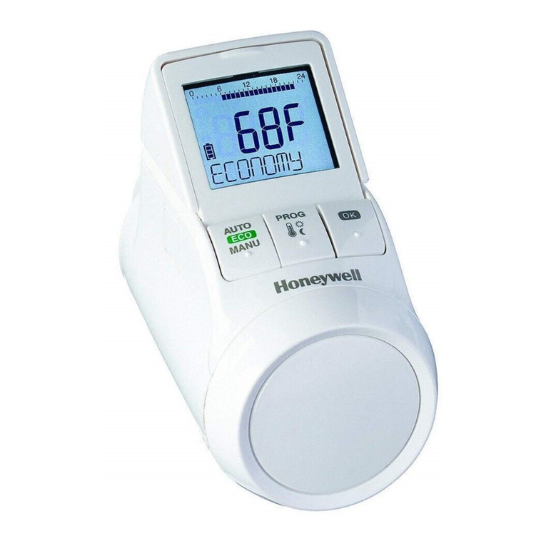
Honeywell TheraPro HR90 User manual
Honeywell
Honeywell HR 80 User manual
Honeywell
Honeywell VR8104 User manual
Honeywell
Honeywell T775M Owner's manual
Honeywell
Honeywell TPPL Modbus TCP Assembly instructions
Honeywell
Honeywell MS7510A2008 User manual
Honeywell
Honeywell Excel 100C User manual
Honeywell
Honeywell ML6284 Operation manual
Honeywell
Honeywell D6 PRO User manual

Honeywell
Honeywell CVL4022ASVAV1 User manual

Honeywell
Honeywell HC900 User manual
Honeywell
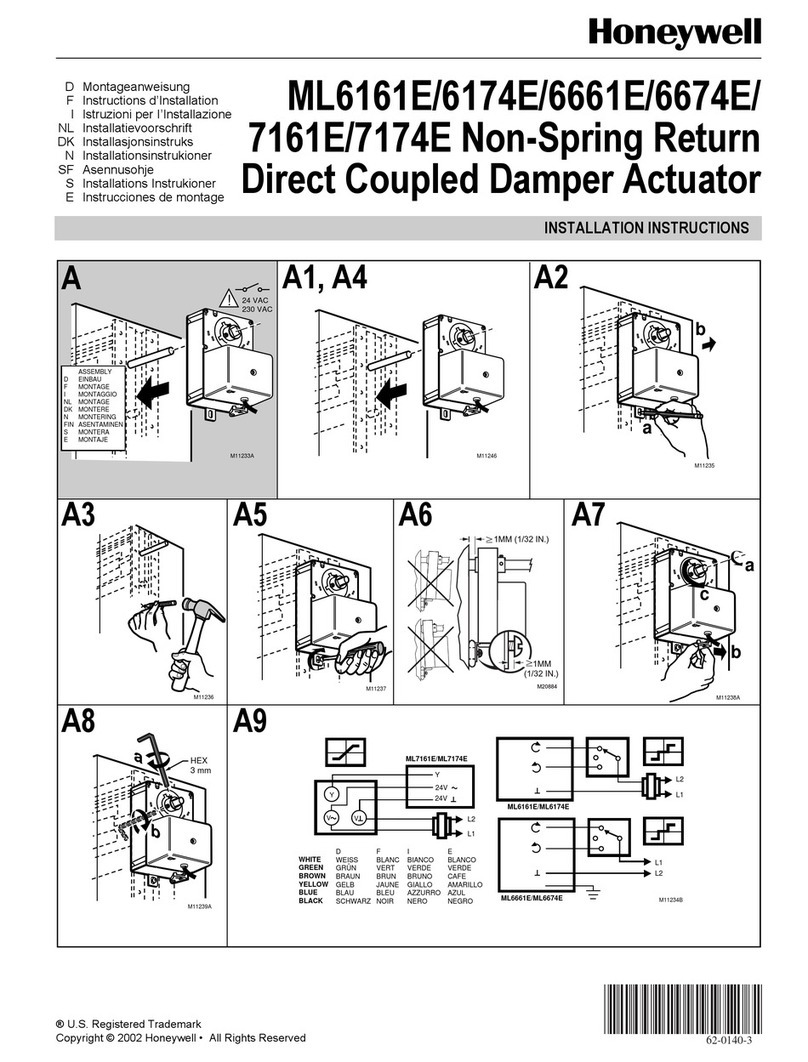
Honeywell ML6161E User manual
Honeywell
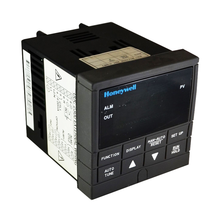
Honeywell UDC 2300 User manual
Honeywell
Honeywell 900U02-0100 Operating manual
Honeywell
Honeywell ControlEdge 900R04-0200 User manual
Popular Controllers manuals by other brands

Digiplex
Digiplex DGP-848 Programming guide

YASKAWA
YASKAWA SGM series user manual

Sinope
Sinope Calypso RM3500ZB installation guide

Isimet
Isimet DLA Series Style 2 Installation, Operations, Start-up and Maintenance Instructions

LSIS
LSIS sv-ip5a user manual

Airflow
Airflow Uno hab Installation and operating instructions
