manuals.online logo
Brands
  1. Home
  2. •
  3. Brands
  4. •
  5. Honeywell
  6. •
  7. Controllers
  8. •
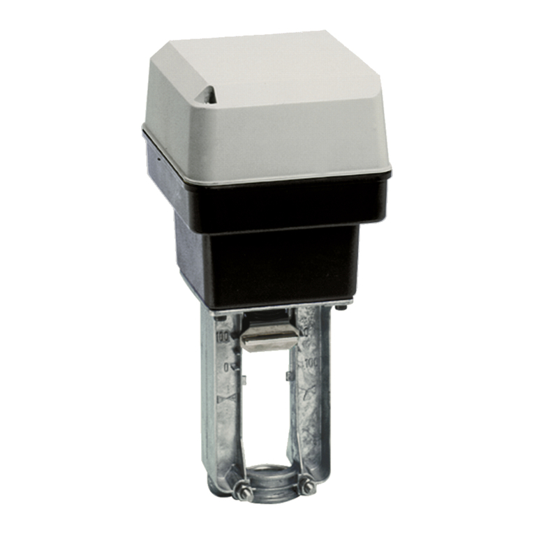
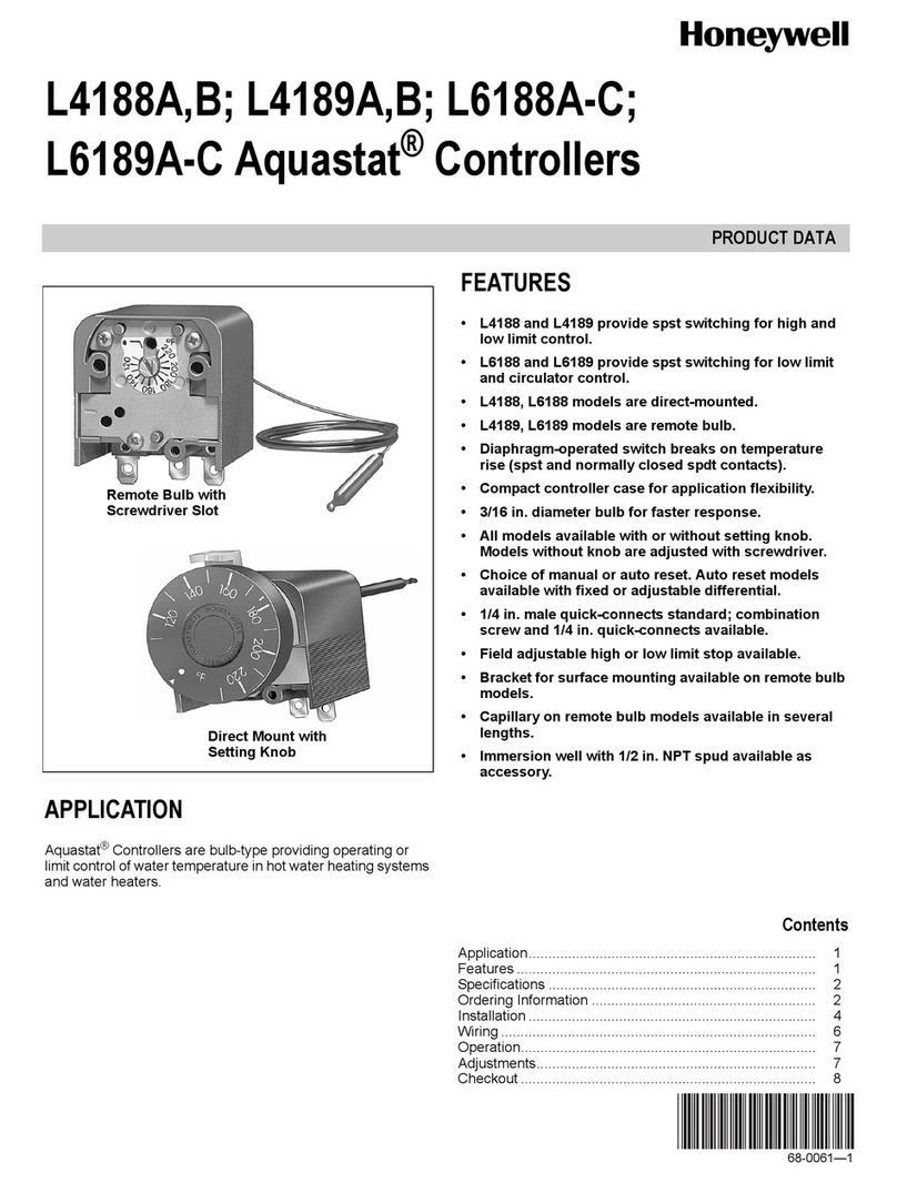
  9. Honeywell MS7510A2008 User manual

Honeywell MS7510A2008 User manual

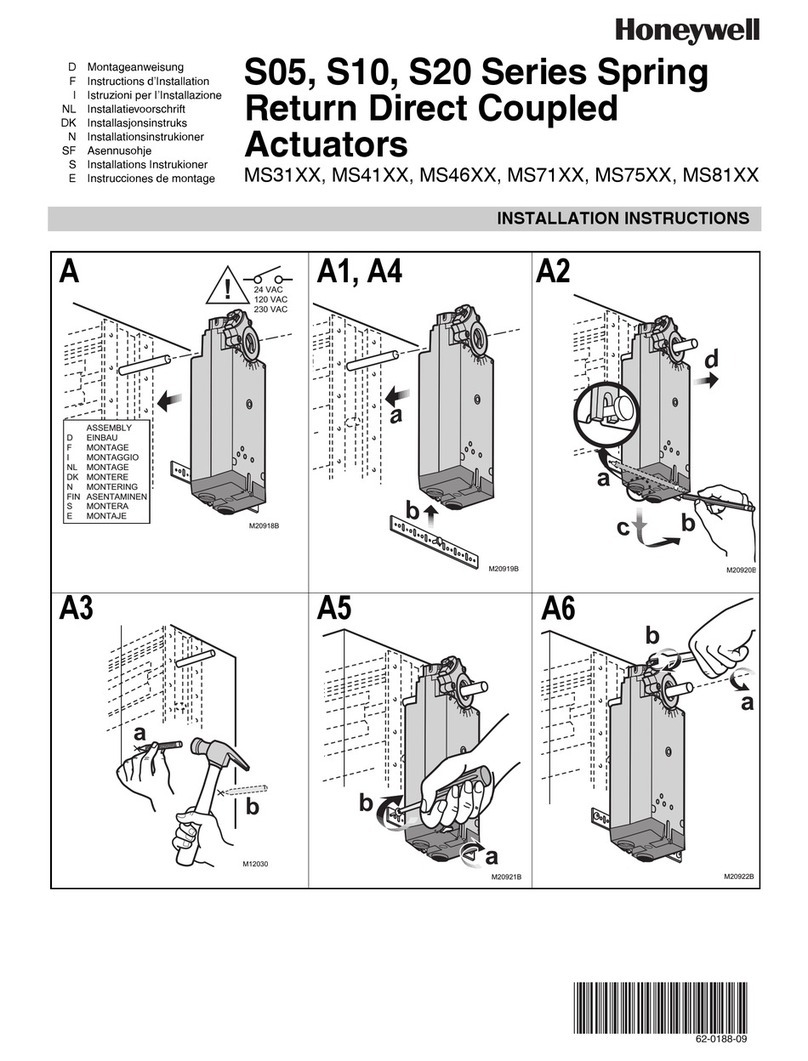
Tools Required:
Wrenches:
(1) 3⁄8in., (1) 7⁄16 in., and (1) 10mm
Mounting shown for damper in
vertical position.
Note: Torque actuator shaft clamp
screw to 88 in./lbs. (9.9Nm).
No. Part Number Qty Description
1 MS actuator
2 415455 4 1⁄4- 20 spinlock nut
3 415586 4 #14 x 3⁄4TEK SMS
4 415934 1 #10-24 nylock nut
5 416048 1 1⁄4x 3⁄8shoulder bolt
6 815027 1 standoff bracket
7 723089 1 mounting bracket
8 415609 4 thread stud
Safety Warning
Equipment damage or electrical power hazard. Line
voltage can cause death or serious injury and short
equipment circuitry. Disconnect power supply before
installation.
These instructions apply to the external field installation of Honeywell actuators on Greenheck model VCD control
dampers when they are duct mounted or sleeved.
®
Honeywell MS4120 MS4620 MS8120 1
®
Document 464287
Honeywell Actuators Direct Drive
MS4120, MS4620, MS8110, MS8120,
MS7510, and MS7520
Installation, Operation and Maintenance Manual
Please read and save these instructions for future reference. Read carefully before attempting to assemble, install,
operate or maintain the product described. Protect yourself and others by observing all safety information. Failure
to comply with these instructions will result in voiding of the product warranty and may result in personal injury
and/or property damage.
Instructions
These installation instructions assume the damper is already
mounted in a duct or sleeve with the damper shaft extending
beyond the duct or sleeve a minimum of 6 inches (152mm).
1. INSTALL THE STANDOFF BRACKET
Dampers with a jackshaft
Jackshaft supplied is typically 1 inch (25mm) diameter.
For these applications the bearing must be removed
from stand-off bracket (item #6). Mount the stand-off
bracket with [4] thread studs (item #8) and [4] 1⁄4-20
splinlock nut (item #2). Orient the stand-off bracket so
the hole is centered on the jackshaft.
Dampers without jackshaft (Shaft Extension)
Mount the stand-off bracket (item #6) spanning across
the damper frame flanges. Fasten to the damper frame
with [4] #14 x 3⁄4Tek screws (item #3). Be sure not to run
the screws into the damper linkage, which is between
the flanges.
2. MOUNT ACTUATOR BRACKET
Mount actuator bracket (item #7) using [4] thread studs
(item #8) and [4] 1⁄4- 20 nuts (item #2).
NOTE: The mounting bracket may be attached in three
positions: parallel with the duct, perpendicular up
from the duct, or perpendicular down from the duct.
Choose a position that offers the most clearance for the
application.
3. ACTUATOR ROTATION
If the fail rotation of the damper is counter clockwise the
universal clamp should be on the side of the actuator
showing the power direction as clockwise rotation
(usually shipped in this orientation).
To change the universal clamp to the other side, remove
the retaining clip and then the universal clamp from the
actuator. Move the universal clamp onto the actuator.
When the clamp is installed, then lock in place using the
retaining clip.
NOTE: All fail rotations refer to the damper shaft rotation
needed to achieve the desire blade fail position. If fail
position is closed, make sure damper blades are fully
close and ensure blade seals are compressed prior to
tightening the actuator clamp to the damper extension
pin or jackshaft. Inspect the damper blades and the
damper shaft to determine the proper damper shaft
rotation for the desired fail position.
4. MOUNTING ACTUATOR
Slide the actuator (item #1) over damper drive shaft.
Install thread stud through the mounting lug on the back
of the actuator and through the corresponding hole of
the actuator bracket (item #7).
Secure the thread stud to actuator bracket with #10-
24 nut. Verify that the damper is in its fail position.
Secure actuator to the damper shaft by torquing the
screw on the actuator universal clamp to 88 in. lbs. .
5. The wiring illustration below identifies actuator electrical
requirements and connections. Wiring must comply
with all applicable electrical codes.
6. Apply power to the actuator. The damper blades
should fully open or close and return to the fail
position when power is disconnected.
Orientation of Stand-off
Bracket for a jackshaft
driven dampers
Orientation of Stand-off
bracket for a directly
driven damper
Black
White
120 Volt o
r
24 volt
M
Wiring Illustration
Wiring Illustration
Important
A break in power of less than one second can cause the
actuator to spring-return 5 degrees or less and remain in
place until a break in power of longer duration.
Model Volts Running Holding
MS4120F1006
120 VAC 35W 10W
MS4120F1204
MS4620F1005
230 VAC 35W 10W
MS4620F1203
MS7510A2008
24 VAC/VDC
14W
5W
MS7510A2206 14W
MS7520A2007 16W
MS7520A2015 22W
MS7520A2205 16W
MS7520A2213 22W
MS8110A1206 24 VAC/VDC 30W 8W
MS8120F1002
24 VAC 45W 10W
MS8120F1200
464287 • MS4120 MS4620 MS8120, Rev. 9, January 2019 Copyright 2019 © Greenheck Fan Corporation2
As a result of our commitment to continuous improvement, Greenheck reserves the right to change specifications
without notice.
Product warranties can be found online at Greenheck.com, either on the specific product page or in the literature
section of the website at Greenheck.com/Resources/Library/Literature.
®
Phone: 715.359.6171 • Fax: 715.355.2399 • Parts : 800.355.5354 • E-mail: [email protected] • Website: www.greenheck.com
Our Commitment

This manual suits for next models

18

Other Honeywell Controllers manuals

Honeywell Centra Line EAGLE Installation and operation manual

Honeywell

Honeywell Centra Line EAGLE Installation and operation manual

Honeywell Lyric Operating instructions

Honeywell

Honeywell Lyric Operating instructions

Honeywell EVOTOUCH CONTROLLER User manual

Honeywell

Honeywell EVOTOUCH CONTROLLER User manual

Honeywell 2RM7800L1087 Service manual

Honeywell

Honeywell 2RM7800L1087 Service manual

Honeywell 1000 Series User manual

Honeywell

Honeywell 1000 Series User manual

Honeywell 7800 SERIES RM7895A User manual

Honeywell

Honeywell 7800 SERIES RM7895A User manual

Honeywell ML6425B User manual

Honeywell

Honeywell ML6425B User manual

Honeywell UDC3500 User manual

Honeywell

Honeywell UDC3500 User manual

Honeywell HC900 User manual

Honeywell

Honeywell HC900 User manual

Honeywell UDC3300 User manual

Honeywell

Honeywell UDC3300 User manual

Honeywell R7284B User manual

Honeywell

Honeywell R7284B User manual

Honeywell S9200U1000 User manual

Honeywell

Honeywell S9200U1000 User manual

Honeywell Excel 800 Installation and operation manual

Honeywell

Honeywell Excel 800 Installation and operation manual

Honeywell Design and Application Product manual

Honeywell

Honeywell Design and Application Product manual

Honeywell 5 Nm Series Operation manual

Honeywell

Honeywell 5 Nm Series Operation manual

Honeywell SEC-H-602 User manual

Honeywell

Honeywell SEC-H-602 User manual

Honeywell UMC800 User manual

Honeywell

Honeywell UMC800 User manual

Honeywell HUPF Series User manual

Honeywell

Honeywell HUPF Series User manual

Honeywell MP953A Operation manual

Honeywell

Honeywell MP953A Operation manual

Honeywell SHC Series User manual

Honeywell

Honeywell SHC Series User manual

Honeywell CENTRA LINE MERLIN NX Series User manual

Honeywell

Honeywell CENTRA LINE MERLIN NX Series User manual

Honeywell V4600 User guide

Honeywell

Honeywell V4600 User guide

Honeywell MS4120S Operation manual

Honeywell

Honeywell MS4120S Operation manual

Honeywell DC33XB User manual

Honeywell

Honeywell DC33XB User manual

Popular Controllers manuals by other brands

Horizon Hobby E-FLITE EFLA1010 instructions

Horizon Hobby

Horizon Hobby E-FLITE EFLA1010 instructions

MRC IOW-924 instruction manual

MRC

MRC IOW-924 instruction manual

Contrec 424 manual

Contrec

Contrec 424 manual

Full Gauge CONV 256 quick start guide

Full Gauge

Full Gauge CONV 256 quick start guide

Inovance H3U Series user guide

Inovance

Inovance H3U Series user guide

AMCOL 6000E Operator's manual

AMCOL

AMCOL 6000E Operator's manual

Production Control Services PCS 3000 Quick reference guide

Production Control Services

Production Control Services PCS 3000 Quick reference guide

Sealey START800 instructions

Sealey

Sealey START800 instructions

AFRISO ARM ProClick instruction manual

AFRISO

AFRISO ARM ProClick instruction manual

Samlexpower SMC-20 owner's manual

Samlexpower

Samlexpower SMC-20 owner's manual

Generac Power Systems Digital Controller R-200A Technical manual

Generac Power Systems

Generac Power Systems Digital Controller R-200A Technical manual

Lennox Wired Controller Installation and operation instructions

Lennox

Lennox Wired Controller Installation and operation instructions

Heatstore HSTIRF Installation & Control Guide

Heatstore

Heatstore HSTIRF Installation & Control Guide

Irritrol Rain Dial-R Quick start guides

Irritrol

Irritrol Rain Dial-R Quick start guides

Toshiba BMS-IFBN1281U-E instruction manual

Toshiba

Toshiba BMS-IFBN1281U-E instruction manual

Teledyne LXT-220 operating instructions

Teledyne

Teledyne LXT-220 operating instructions

BFT IGEA LB Installation and user manual

BFT

BFT IGEA LB Installation and user manual

Gammaflux GLC 2k Setup guide

Gammaflux

Gammaflux GLC 2k Setup guide

manuals.online logo
manuals.online logoBrands
  • About & Mission
  • Contact us
  • Privacy Policy
  • Terms and Conditions

Copyright 2025 Manuals.Online. All Rights Reserved.