manuals.online logo
Brands
  1. Home
  2. •
  3. Brands
  4. •
  5. Honeywell
  6. •
  7. Controllers
  8. •
  9. Honeywell R7426A User manual

Honeywell R7426A User manual

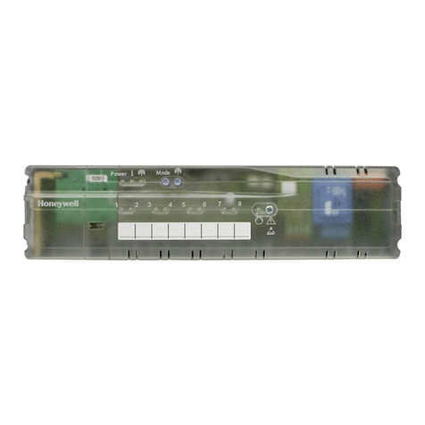
PRODUCT DATA
63- 2565
® U.S. Registered Trademark
Copyright © 2000 Honeywell Inc. • All Rights Reserved
R7426A,B,C,D
Temperature and
Universal Input Controllers
TIME-INDEPENDENT CONTROLLERS
APPLICATION
R7426A,B,C Temperature Controllers use directdigital control
technology to provide more accurate and efficient operation of
heating, ventilation and air conditioning (HVAC) systems.
Parametersare preset for plug and play operation and provide
different control strategies for optimum system performance.
The controller performs proportional or proportional plus
integral (P+I) control and covers all space, supply air or water
flow applications within the specified ranges of 32°F to 122°F
(0°C to 50°C) or 32°F to 266°F (0°C to 130°C). Standard
Pt 1000 or NTC 20K ohm temperature sensors can be used.
The modern design with its easy to operate user interface and
LCD allows complete flexibility of control system design,
accurate parameter setting, and display of actual temperature
values, setpoints and outputs.
The R7426D Universal Input Controller covers all space or
discharge air humidity control applications and special
applications, such as pressure control, within 0 to 10 Vdcinput
ranges. The controller provides input span adjustment to
match the transmitter output specification.
FEATURES
• Selectable proportional, proportional plus integral
(P+I), or (R7426D only) proportional plus integral plus
derivative (P+I+D) control.
• Pre-programmed control parameters.
• Digital parameter setting.
• Selectable direct/reverse acting output.
• 24 Vac power supply.
R7426A,B,C
• 3 inputs for temperature sensors.
• Automatic sensor type identification of Pt 1000 or
NTC 20K ohm.
• 3 digital inputs for plant/system On/Off, occupancy
(alternatively summer/winter changeover) and freeze
protection.
• Dehumidification control via humidity deviation input.
• Selectable floating output functions:
— Floating.
— 2, 3, 4, 6 or 15 stage On/Off (TRIAC).
— Pulse width modulation (PWM).
• Analog outputs 0/2 to 10Vdc selectable.
• Start-up routine.
• Space/supply limit or cascade control.
• Sequence control of heating, mixed air damper or
energy recovery system and cooling.
R7426D
• 2 analog inputs 0 to 10Vdc for transmitters.
• Control output monitoring and manual output signal
override.
• Master/submaster cascade control.
• Main variable control and optional high/low limit control.
• Input span adjustment.
• Temperature compensation input.
• Optional remote setpoint adjustment. Contents
Application ....................................................................... 1
Features ........................................................................... 1
Specifications ................................................................... 2
Ordering Information ........................................................ 2
Installation ........................................................................ 3
Operation ......................................................................... 4
Operating Overview ......................................................... 8
Appendix .......................................................................... 10
Control And Configuration Parameters ....................... 10
Parameter Details ....................................................... 12
R7426A,B,C,D TEMPERATURE AND UNIVERSAL INPUT CONTROLLERS
63-2565 2
ORDERING INFORMATION
When purchasing replacement and modernization products from your TRADELINE® wholesaler or distributor, refer to the
TRADELINE® Catalog or price sheets for complete ordering number.
If you have additional questions, need further information, or would like to comment on our products or services, please write or
phone:
1. Your local Home and Building Control Sales Office (check white pages of your phone directory).
2. Home and Building Control Customer Logistics
Honeywell Inc., 1885 Douglas Drive North
Minneapolis, Minnesota 55422-4386 (612) 951-1000
In Canada—Honeywell Limited/Honeywell Limitée, 155 Gordon Baker Road, North York, Ontario M2H 3N7.
International Sales and Service Offices in all principal cities of the world. Manufacturing in Australia, Canada, Finland, France,
Germany, Japan, Mexico, Netherlands, Spain, Taiwan, United Kingdom, U.S.A.
SPECIFICATIONS
Models:
R7426A: Temperature Controller with floating, PWM, and 2 or
3-stage On/Off outputs.
R7426B: Temperature Controller for sequence control of
heating, energy recovery, and cooling. Floating, PWM, and
2,3,4,6, or 15-stage On/Off outputs.
R7426C: Temperature Controller for sequence control of
heating, energyrecovery or mixed-air damper, and cooling,
or to drive step controllers. Analog 0/2 to 10 Vdc output.
R7426D: Universal Input Controller with two transmitter inputs
for master/submaster cascade control, or main and
optional high or low limit control. One temperature
compensation input to provide main setpoint reset. One
analog output and one deviation signal output.
Dimensions: See Fig. 1.
Weight: 0.55 lb (250g).
Mounting: Back panel, wall, DIN rail, or (with panel mounting
accessory frame) front panel.
Electronic:
Microcontroller: 8-bit, 10-bit A/D converter, EEPROM and LCD.
Power supply: 24 Vac +10, -15%, 50/60Hz.
Power consumption: 3 VA.
Wiring:
Maximum Wiring Run from Controller to All Devices:
18 AWG: 328 ft (100m).
16 AWG: 492 ft (150m).
Offset Due to Wire Resistance: See Table 2.
Ambient Ratings:
Temperature:
Operating: 32°F to 122°F (0°C to 50°C).
Storage: -31°F to +158°F (-35°C to +70°C).
Humidity: 5 to 95% relative humidity, non-condensing.
Digital Inputs:
Occupancy (Summer/Winter Changeover) (R7426A,B,C only):
Operation Mode: Unoccupied (Winter), Occupied (Summer).
Potential Free Contact: open > 40kW, closed < 100W.
Freeze Protection (R7426A,B,C only):
Operation Mode: Freeze protection (normal).
Potential Free Contact: open > 40kW, closed < 100W.
Plant System On/Off:
Potential-Free Contact: open (off) greater than 40 kW,
closed (on) less than 100W.
Accuracy: ±0.9°F (±0.5K) (not including sensor inaccuracy).
Analog Inputs:
All Models: I03: Temperature compensation sensor.
R7426A,B,C Temperature Inputs:
I01: Main sensor.
I02: Limit or cascade sensor.
R7426D Universal Inputs (0 to100%, adjustable 0to 10 Vdc span):
I01: Main sensor.
I02: Limit or cascade sensor.
Outputs:
R7426A,B,C:
TRIAC (selectable) (Maximum Load: 450 mA at 24 Vac.):
Floating: Single-pole, double-throw (spdt) switching.
2,3,4,6 or 15-stage: On (24 Vac) / Off (0 Vac).
Pulse width modulation: 0 to 100% based on run time.
Humidity Deviation (optional): -5 to 5 Vdc, 200 mV/%rh.
Maximum Load: 450 mA at 24 Vac.
Analog (R7426C,D only):
Control Range: 0/2 to 10 Vdc (0 to 100%).
Full Range: 0 to 12 Vdc.
Maximum Load: 1.2 mA at 12 Vdc.
R7426D:
On/Off: Delay adjustable single-pole, single-throw (spst) switching.
Maximum Load: 450 mA at 24 Vac.
Deviation Signal:
Deviation Range: -5 to 5 Vdc (-25 to +25%), 200 mV/%.
Maximum Load: 0.5 mA at 5 Vdc.
Analog Output (O1):
Control Range: 0/2 to 10 Vdc (0 to 100%).
Full Range: 0 to 12 Vdc.
Maximum Load: 1.2 mA at 12 Vdc.
Sensor Ratings:
Temperature Range:
Pt 1000: -22°F to 266°F (-30°C to +130°C).
NTC 20K ohms (selectable):
-22°F to 185°F (-30°C to +85°C).
-22°F to 266°F (-30°C to +130°C).
Characteristics:
Pt 1000: 1000 ohms at 32°F (0°C).
NTC 20K ohms: 20K ohms at 77°F (25°C).
Control ranges:
R7426A,B,C: 32°F to 122°F (0°C to 50°C) or 32°F to 266°F
(0°C to 130°C).
R7426D: 0 to 100%.
Control Point Adjustments (CPA)/Setpoint Adjustments
(SPA): See Accessories and Table 1.
R7426A,B,C,D TEMPERATURE AND UNIVERSAL INPUT CONTROLLERS
3 63-2565
Approvals:
Protection class II.
NEMA 1, IP30 or (with front panel mounting only) IP40.
FCC Part 15, Class B.
Accessories:
43193862-001 Front panel mounting frame.
NTC 20K ohm sensors for CPATYP 3 (10 to 20K ohms):
C7031B1033: For duct discharge air, hot water.
C7031D1062: For hot or chilled water.
C7031F1018: For outdoor air temperature.
C7031J1050: For duct discharge air (averaging).
C7031K1017: For hot or chilled water (strap-on).
T7770A1006: Wall module with locking cover.
T7770B1004: Wall module with locking cover and setpoint
adjustment knob (55°F to 85°F).
Pt 1000 sensors for CPATYP 1:
C7031D1070: For hot or chilled water.
C7031F1026: For outdoor air temperature.
C7031J1068: For duct discharge air (averaging).
C7031K1025: For hot or chilled water (strap-on).
Table 1. CPA/SPA Selectable Inputs.
aDefault value.
Table 2. Sensor Offset Per 33 ft (10m) of Wire.
INSTALLATION
When Installing this Product...
1. Read these instructions carefully. Failure to follow them
could damage the product or cause a hazardous
condition.
2. Check the ratings given in the instructions and on the
product to make sure the product is suitable for your
application.
3. Installer must be a trained, experienced service
technician.
4. After installation is complete, check out product operation
as provided in these instructions.
Mounting
The controller can be mounted in an electric cabinet or other
suitable enclosure. They are suitable for back panel, wall, and
DIN rail mounting.
Fig. 1. R7426 Dimensions.
Back Panel or Wall Mounting
1. Drill two holes in the mounting surface (see Fig. 1).
2. Remove the controller from the baseplate:
a. Insert a flat head screwdriver into the slot at the right
side of the control face.
b. Pull control right side slightly away from baseplate.
c. Insert a flat head screwdriver into the slot at the left
side of the control face.
d. Pull the controller away from the baseplate.
3. Mount the baseplate to the surface.
4. Replace the controller on the baseplate.
DIN Rail Mounting
1. Remove the controller from the baseplate:
a. Insert a flat head screwdriver into the slot at the right
side of the control face.
b. Pull control right side slightly away from baseplate.
c. Insert a flat head screwdriver into the slot at the left
side of the control face.
d. Pull the controller away from the baseplate.
2. Mount the baseplate to the TS35 DIN rail.
3. Replace the controller on the baseplate.
Wiring
CAUTION
Electrical Shock or Equipment Damage Hazard.
Can shock individuals or short equipment
circuitry.
Disconnect power supply before installation.
IMPORTANT
All wiring must agree with applicable codes,
ordinances and regulations.
Connect the wires to the device:
1. Strip 3/8 in. to 1/2 in. of insulation from the controller
end of each wire.
2. Insert each wire into the appropriate terminal on the top
or bottom of the device (see Fig. 2 and 3):
a. Solid wire: Push stripped end into terminal.
b. Stranded wire: Apply pressure to numbered indent
corresponding to the terminal while inserting wire.
3. Apply power to the device.
CPATYP
Value Sensor
(in ohms) CPA/SPA range
0ainternal CPA: ±9°F
1 9574 to 1426
2 100K to 0
4 0 to 10K
3 9574 to1426 SPA: 59°F to 86°F (15°C to 30°C)
5 0 to 100K
6 0 to 100K SPA: 32°F to 122°F (0°C to 50°C)
or 32°F to 266°F (0°C to 130°C).
Wire Type
in AWG (mm2)Temperature offset in °F (°C)
Pt 1000 NTC
20 (0.5) 0.32 (0.18) negligible
17 (1.0) 0.16 (0.09)
15 (1.5) 0.11 (0.06)
+
–
SEL
SET
4-1/8
(105)
3-7/16
(87)
1-7/16
(37)
6 (152)
4-5/8 (118) 1/8 (3) DIAMETER
WALL MOUNTING M17411
R7426A,B,C,D TEMPERATURE AND UNIVERSAL INPUT CONTROLLERS
63-2565 4
Fig. 2. R7426A,B typical wiring.
Fig. 3. R7426C,D typical wiring.
OPERATION
Main Temperature Control
The controller compares the actual temperature value
measured by the main sensor (I01) with the calculated setpoint
(CTRP1) and generates a proportional (Xw) or proportional
plus integral (Xwi) deviation signal. CTPR1 is the sum of the
compensation effect, the CPA and the unoccupied offset.
NOTE: All diagrams show proportional control action only. If
P+I controlis in operation heating and cooling slopes
are not defined.
2515 16 17 18 19 20 21 22 23 24 26 27 28
R7426A
2
1112345678910 12
OFF
ON
13 14
L1
(HOT)
L2
+–
CLOSE
OUT OPEN
OUT
IO1
CPA/SPA
UNOCCUPIED FREEZE
PROTECTION
OFF
ON
PLANT/
SYSTEM
OCCUPIED
MAIN
TEMPERATURE
SENSOR
LIMIT OR
CASCADE
SENSOR
COMPENSATION
SENSOR
+–
IO2
O1
+–
IO3
HONEYWELL
SERIES 61
ACTUATOR
2515 16 17 18 19 20 21 22 23 24 26 27 28
R7426B
2
1112345678910 12
OFF
ON
13 14
+–
CLOSE
OUT OPEN
OUT CLOSE
OUT OPEN
OUT CLOSE
OUT OPEN
OUT
IO1
CPA/SPA
UNOCCUPIED FREEZE
PROTECTION
OFF
ON
PLANT/
SYSTEM
OCCUPIED
MAIN
TEMPERATURE
SENSOR
LIMIT OR
CASCADE
SENSOR
COMPENSATION
SENSOR
+–
IO2
O1
+–
IO3
M17483
1
2
3
POWER SUPPLY. PROVIDE DISCONNECT MEANS AND OVERLOAD PROTECTION AS REQUIRED.
TERMINALS 13 AND 14 ARE A SERIAL INTERFACE FOR A PANEL BUS.
RELATIVE HUMIDITY INPUT IS EQUAL TO 200 mV DIVIDED BY PERCENT RH.
O2 O3
3
L1
(HOT)
L2
1
1
HUMIDITY
SENSOR
+–
XWRH HONEYWELL
SERIES 61
ACTUATOR
HONEYWELL
SERIES 61
ACTUATOR
HONEYWELL
SERIES 61
ACTUATOR
2515 16 17 18 19 20 21 22 23 24 26 27 28
R7426D
M17446
2
1112345678910 12
OFF
ON
ON/OFF
OUTPUT
13 14
1
2
3
4
4
POWER SUPPLY. PROVIDE DISCONNECT MEANS AND OVERLOAD
PROTECTION AS REQUIRED.
TERMINALS 13 AND 14 ARE A SERIAL INTERFACE FOR A PANEL BUS.
L1
(HOT)
L2
1
+–
IO1
CPA/
SPA
0/2 TO 10 Vdc
OUTPUT
FREEZE
PROTECTION
OFF
ON
PLANT/
SYSTEM
COMPENSATION
SENSOR
+–
+–
IO2
O1
+–
IO3
HONEYWELL
SERIES 70
ACTUATOR
RELAY
2515 16 17 18 19 20 21 22 23 24 26 27 28
R7426C
2
111234 5 678910 12
OFF
ON
13 14
1
3
L1
(HOT)
L2
+–
IO1
CPA/SPA
0/2 TO
10 Vdc
OUTPUT
0/2 TO
10 Vdc
OUTPUT
0/2 TO
10 Vdc
OUTPUT
UNOCCUPIED
FREEZE
PROTECTION
OFF
ON
PLANT/
SYSTEM
OCCUPIED
MAIN
TEMPERATURE
SENSOR
LIMIT OR
CASCADE
SENSOR
COMPENSATION
SENSOR
+–
+–+–+–
IO2
O1 O2 O3
+–
IO3
HUMIDITY
SENSOR
+–
XWRH HONEYWELL
SERIES 70
ACTUATOR
HONEYWELL
SERIES 70
ACTUATOR
HONEYWELL
SERIES 70
ACTUATOR
RELATIVE HUMIDITY OUTPUT (Xw). EQUAL TO 200 mV DIVIDED BY PERCENT RH.
RELATIVE HUMIDITY INPUT IS EQUAL TO 200 mV DIVIDED BY PERCENT RH.
R7426A,B,C,D TEMPERATURE AND UNIVERSAL INPUT CONTROLLERS
5 63-2565
R7426 Temperature Control
Depending on the deviation signal, the control output (O1)
value is calculated and converted to a floating signal. Select
director reverse action using theDIR/REV parameter (cooling
is Dir, heating is Rev). The throttling range setting (Xp1)
controls the output span.
The startpoint Ostart determines the midrange shift of the
output (O1) from the calculated setpoint (CTRP1).
Limit Control (Wlim, Xp2 and tr2)
The R7426 controller offers limit control (Wlim) by comparing
the deviation signals of the main and limit control loops. The
lowest (low limit control) or highest (high limit control)
deviation signal is selected and fed to the output stage.
High limit control is performed when parameter LimTyp is 1.
Low limit control is performed when parameter LimTyp is 0.
During limit control, throttling range (Xp2) and reset time (tr2)
are active.
NOTES: Limit control is active only if either:
—I02 temperature sensor (parameter I02ext is 0) is
connected, or
—I01 sensor (control parameter I02ext is 1)
supplies the control loop.
Cascade Control (Wcas, Rcas and tr2)
The R7426 provides cascade control using two control loops
(master and submaster) to maintain setpoint (CTRP1).
At zero room temperature deviation (XWMaster), discharge
temperature (I02) is controlled by the programmed setpoint
(Wcas = CTRP2). If room temperature deviates, submaster
setpoint (CTRP2) is altered. See Fig. 4.
—Reset span adjustment (Rcas) determines degree of reset
effect.
—Integral reset time and throttling range of submaster P+I
control can be adjusted with tr2 and Xp2.
—CTRP2 high limit is performed if LimTyp is 1.
—CTRP2 low limit is performed if LimTyp is 0.
Fig. 4. Cascade control.
NOTES: Offs varies depending on the control mode:
—Occupied: Offs is 0. (See Fig. 6.)
—Unoccupied: Offs is SOFFS.
—Night: Offs is NOFFS.
R7426B,C Control with Heating, Mixed Air
Dampers and Cooling
Sequence Control
This application will be active with the R7426B,C controllers
when I02 is not connected. It can be used for sequence
control of a heating valve, an energy recovery system or a
mixed air damper and a cooling valve.
The characteristic of each output can be selected via the
parameters DIR/REVx (where x is O1, O2 or O3). Fig. 5 shows:
•Dir characteristic for all outputs.
•Control of damper signal within the range Xp1.
NOTE: If no cooling actuator is available, the parameter Xpc
can be set to Off and damper output is maintained at
100 percent above control point (CTRP1).
If damper output should be descreased to MINPOS level
above CTRP1 (see Fig. 5), or if no cooling actuator is
available, parameter Xpc must be adjusted to a value
between 2°F and 72°F.
Fig. 5. R7426B,C direct/reverse action.
Temperature Cascade Control
This application will be active with the R7426B,C controllers if
parameter Wcas is set to any value other than Off. It can be
used for sequence control of: a heating valve, an energy
recovery system, or mixed air damper and cooling valve.
Three cascade control modes are available:
•With occupied (contact closed) mode. (See Fig. 6.)
•With unoccupied (contact open) mode. See Cascade
Control section (Fig. 4).
•With night mode. See Cascade Control section (Fig. 4).
Each output characteristic can be selected via parameters
DIR/REVx (where x is O1, O2 or O3). Fig. 5 shows:
•Dir characteristic for all outputs.
•Control of damper signal within the range Xp2.
NOTE: If no cooling actuator is available, the parameter Xpc
can be set to Off.
If parameter Xpc is Off, the cooling signal is set to 0 percent
and damper output is maintained at 100 percent above control
point (CTRP1).
M17450
IO1
0
CTRP1
CTRP2 Xw MASTER
MASTER
SUBMASTER
Xp/2
Xp/2
0Xw MASTER
1
1 2WHEN LimTyp IS 1.
2
WHEN LimTyp IS 0.
Offs
Offs
W
2x
RWCAS
CAS
LIM
WLIM
M17447
O1
IO1
Y
100%
00
REV DIR
CTRP1
Xw
Xp1 START
R7426A,B,C,D TEMPERATURE AND UNIVERSAL INPUT CONTROLLERS
63-2565 6
Fig. 6. Occupied Cascade Control.
—CTRP2 high limit is performed if parameter LimTyp is 1.
—CTRP2 low limit is performed if parameter LimTyp is 0.
Economizer Modes
Economizer modes are suitable for installations where the
main temperature sensor (I01) is installed in either exhaust air
or the room with a constant offset between room and exhaust
air conditions. The offset value is programmable within 0°F to
9°F with parameter RetOffs which will be added to the actual
room temperature value to simulate exhaust air conditions.
NOTE: Economizer mode is disabled if parameter RetOffs is
programmed Off, or no OAT sensor is connected.
By comparing the conditions of outside air with exhaust air,
the O1 output on the three-output controller operates using
Mixed Air Dampers or an Energy Recovery System:
Economizer Mixed Air Damper Mode
Economizer mixed air damper mode is active when:
•RetOffs is not Off.
•DIR/REVO1 is Dir.
NOTE: See Table 3 for control logic.
Table 3. Economizer Mixed Air Damper Mode.
NOTE: A fixed hysteresis of 2°F is used to switch between
MINPOS and O1.
Economizer Energy Recovery System
Economizer mixed air damper mode is active when:
•RetOffs is not Off.
•DIR/REVO1 is Rev.
NOTE: See Table 4 for control logic.
Table 4. Economizer Energy Recovery System Mode.
NOTE: A fixed hysteresis of 2°F is used to switch between
100 percent and O1.
Controller Functions
Outside Air Temperature Compensation
Outside air temperature compensation is performed when I03
is connected. The parameter Wcomp defines the summer and
winter compensation changeover point. Parameters Wi and
Su define the degree of summer and winter compensation.
Fig. 7. OAT Compensation.
When Dir/RevO1 = Rev (heating control):
When Dir/RevO1 = Dir (cooling control):
•Winter compensation is performed if .
•Summer compensation is performed if .
SMOOTHING FILTER FOR OUTSIDE AIR TEMPERATURE INPUT
A smoothing filter for OAT input I03 is incorporated to
eliminate sudden temperature variations. This provides more
stable control system operation.
Summer/Winter Changeover Function
Occupancy input can alternatively be used for summer/winter
changeover. Activate the summer/winter changeover function
by setting the control parameter DIR/REVO1 to Cho.
NOTE: This is provided only on the R7426A controller.
A potential free contact can be used between terminals 1 and
4 to switch the controller mode to heating (contact open) or
cooling (contact closed).
Freeze Protection
See Table 5 for actions executed when the contact connected
to the freeze protection input is opened. A closed contact
performs frost recovery (see Table 6).
NOTE: Freeze protection operation takes priority over all
other control operations.
Outside Air Temperature O1
Greater than exhaust air
temperature MINPOS
Less than exhaust air
temperature Included in direct acting
heating sequence control
M17448
IO1
0
CTRP1
CTRP2 Xw MASTER
MASTER
SUBMASTER
Xp
0
W
Xw MASTER
2x
RWCAS
CAS
1
1 2WHEN LimTyp IS 1.
2
WHEN LimTyp IS 0.
LIM
WLIM
Outside Air Temperature O1
Greater than exhaust air
temperature 100 percent
Less than exhaust air
temperature Energy Recovery System
included in heating sequence
control. MINPOS is not active.
M17451
CTRP1 Su
Wcomp
W1+XOFFS+CPA
IO3
Wi
XOFFS OFFS–=
XOFFS OFFS=
I03 WCOMP
<
I03 WCOMP
>
R7426A,B,C,D TEMPERATURE AND UNIVERSAL INPUT CONTROLLERS
7 63-2565
Dehumidification Control (Humidity Deviation Input)
Dehumidification control is available only on the R7426B,C
controllers (three outputs). Use it to connect a humidity
controller. The R7426 compares the deviation input signal
from the humidity controller (Xwrh) with the temperature
control cooling deviation signal (Xwc). The signal with the
highest cooling demand is used to control cooling output (O2).
Table 5. Freeze Protection Actions.
Table 6. Frost Recovery.
Output Functions
The controller provides a choice of output signals suitable for
operating a range of final control devices. Suitability is based
on the parameter setting of OMode and OxMode (where x is
1, 2 or 3) parameters.
R7426A and R7426B
FLOATING VALVE OR DAMPER ACTUATORS (FLOATING MODE)
Parameter setting for Heating/Cooling Control Outputs:
OMode is 0; OxMode (where x is 1, 2 or 3) is 0.
The controller converts the deviation signal to a proportional
output pulse which drives the actuators depending on the
Runtimex (where x is O1, O2 or O3) parameter value.
An automatic synchronization function ensures correct
actuator positioning. This is performed by periodically running
all actuators to the closed position. Synchronization run time
is derived by control parameter Runtimex (where x is O1, O2
or O3) multiplied by 1.25.
Synchronization by the controller is initiated:
•After power up reset (initial start).
•After 250 control steps with control output below 5 percent.
•If plant/system On/Off input is switched to Off.
ELECTRIC HEAT CURRENT VALVE (PWM OUTPUT)
PWM output is suitable for driving electric heat current valves.
It is controlled from the heating signal. The interval or total
cycle time is set by parameter Runtimex (where x is O1 or O3).
EXAMPLE:With 60 percent Output Signal and Motor
Runtimex (where x is O1 or O3) set to 50 sec,
OMode is 0, OxMode (where x is 1 or 3) is 3.
2-STAGE ON/OFF SEQUENCE CONTROL
The R7426A,B controllers convert the output signal into a
2-stage On/Off sequence output signal suitable for operating
relays. Two relays can be connected to provide sequence
control of two stages (such as electric heat stages).
Parameter setting for Output Switching Position:
•OMode is 0.
•OxMode (where x is 1, 2 or 3) is 1.
3-STAGE BINARY ON/OFF SEQUENCE CONTROL
The R7426A,B controllers convert the heating signal into a
3-stage binary On/Off sequence.
Parameter setting for Output Switching Position:
•OMode is 0.
•OxMode (where x is 1 or 3) is 2.
Outputs for R7426B only
4-STAGE ON/OFF ELECTRIC HEATING OR COOLING
When OMode is 2, the O3/O1 output sequence is controlled from
the heating signal and O2 is controlled from the cooling signal.
When OMode is 3 the O3/O1 output sequence is controlled from
the cooling signal and O2 is controlled from the heating signal.
For temperature control sequence, see Temperature
Sequence Control with Heating, Mixed Air Dampers and
Cooling section.
NOTES:
—Mixed air damper operation is not available.
—Output O2 operates in accordance with O2Mode.
6-STAGE ON/OFF SEQUENCE CONTROL HEATING OR COOLING
The output sequence of O3/O2/O1 is controlled from one
output signal. (See Main Temperature Control or R7426A
Cascade Control.)
15-STAGE BINARY ON/OFF ELECTRIC HEATING AND COOLING
The output sequence of O3/O1 is controlled from the heating
signal. The output sequence of O2 is controlled from the
cooling signal (see Temperature Sequence Control with
Heating, Mixed Air Dampers and Cooling section). O2 output
is operated in accordance with O2Mode.
NOTE: The mixed air damper operation is not available.
Fig. 8. 15-stage binary on/off electric heating and cooling.
Model
Output Function Freeze Protection Action
DIR/
REVO1 Su/Wi
Changeover Outputs (in percent)
O1 O2 O3.
R7426A Dir —0——
Rev —100 ——
Cho Cooling 0 ——
Cho Heating 100 ——
R7426B —— 00100
R7426C 0 0 100
Model
Conditions of
Outdoor
Temperature (I03) Frost Recovery
R7426A
R7426B
R7426C
Greater than 43°F
(6°C) or I03 not
connected
Main temperature control
Less than 43°F (6°C) Setpoint W1 temporarily
raised by Xp1 and linearly
decreased to normal value
over approximately 10 min
M17452
POWER
STEP 1 ON
STEP 2 ON
STEP 14 ON
STEP 15 ON
ON
OFF O3/O1
4 SIGNAL SEQUENCE
OF O3/O1 OUT1/OUT2
4.5 11
6.5 13 89 95.5 100%
6.5 13
R7426A,B,C,D TEMPERATURE AND UNIVERSAL INPUT CONTROLLERS
63-2565 8
Two Position Damper Control (R7426B,C)
If parameter OMode is 4, then the R7426B,C damper output
signal O1 operates as a two-position control:
•When the On/Off input signal is On: O1 is 100 percent.
•When the On/Off input signal is Off: O1 is 0 percent.
•For the O2/O3 output sequence, see the Temperature
Sequence Control with Heating, Mixed Air Damper and
Cooling section.
NOTE: The start-up routine must be disabled.
Analog Output (R7426C only)
Three dc output control signals are provided to control
actuators for valves, dampers, or pneumatics (through E/P
transducers).
The full output range is 0 to 12 Vdc. The control range is
common to all outputs and is software configurable to either:
2 to 10 Vdc, or 0 to 10 Vdc.
NOTE: Use the parameter ORange to configure the output.
Adjustments
Control Point / Setpoint Adjustment (CPATYP)
The control or setpoint can be adjusted using an internal or
external potentiometer connected to the CPA/SPA input (see
Technical Data). The CPA/SPA type is selected by the control
parameter CPATYP (see Technical Data).
Temperature Sensor Calibration (I01CAL, I02CAL
and I03CAL)
In case of an offset resulting from long wiring lengths, the
temperature sensor inputs (I01, I02 and I03) can be adjusted
separately using parameters I01CAL, I02CAL and I03CAL.
OPERATING OVERVIEW
Display and Operation Elements
NOTES: Pressing the + or - button modifies values or scrolls
through the parameter list:
—One press: single step.
—Pressing and holding: automatically modifies
value or scrolls through list.
—After 3 seconds of pressing without release:
speed of modification/scrolling increases.
Changing Operating Modes
After power-up, the controller version is displayed (see
Fig. 9) and the controller enters standard display mode (see
Fig. 10). This mode displays selected input/output values.
NOTE: Although the R7426A,B,C have four control modes
(see Fig. 10), the R7426D controller has only Off and
On. (The On icon is the same as the Occupied icon.)
Fig. 9. Controller Version.
Parameter Selection/Adjustment
Use this mode for application configuration:
1. Press and hold the + and - buttons to display parameter
selection mode.
2. Press + until the desired parameter is displayed.
3. Press SET to enter adjustment mode.
4. Use + and - to adjust parameter to desired setting.
5. Return the controller to selection mode using either:
a. SET places the parameter value into the EEPROM.
b. SEL discards the change.
To Display Actual Values
In standard display mode, one of six actual values can be
selected and displayed (see Table 7) by pushing SEL.
Fig. 10. R7426 display.
Resetting Parameter Values to Default
To reset all parameter values to default (see Tables 9 and 10
for default values):
1. Press and hold the + and - buttons prior to and during
power up.
2. When the display starts flashingdEF, release the buttons.
NOTE: R7426D controllers also have the DefProg (C.23)
parameter. Setting DefProg to 1 resets parameter
values to default.
Time out
After approximately 10 minutes of inactivity (no buttons
pressed) the controller automatically returns to standard
display mode. Inputs not yet confirmed by the SET button are
discarded and old parameter values retained.
Table 7. Standard Displays.
M17458
R7426A:
R7426B:
R7426C:
R7426D:
1
1
WHEN POWER IS APPLIED, THE
DISPLAY FLASHES MODEL CODE:
Display Description
I01 I01
CP.1 Main Setpoint CTRP1
I02 I02
CP.2 Limit/Cascade Setpoint CTRP2
I03 I03
%rh Humidity Deviation Xwrh
O1 Output 1
O2 Output 2
O3 Output 3
M17462
FREEZE
PROTECTION OFF
CONTROL MODE
NIGHT UNOCCUPIED OCCUPIED
+
R7426A,B,C,D TEMPERATURE AND UNIVERSAL INPUT CONTROLLERS
9 63-2565
Selecting Output Values
Output selection mode displays the output value and indicates
manual overrides. An activated manual override is indicated
by a displayed F(fixed).
NOTE: Press the SET button to enter adjustment mode.
Output Manual Overrides
Use this mode for manual override. It is especially useful
during installation and setup:
1. Press and hold the SET and SEL buttons to display
output data selection mode.
2. Press + until the desired parameter is displayed.
3. Press SET to enter adjustment mode.
4. Use + and - to adjust the output to the desired value.
5. Return the controller to selection mode using either:
a. SET changes the output.
b. SEL discards the change.
6. To disable the manual override:
a. Repeat steps 2 and 3.
b. Press and hold + and - until the device displays rEL.
NOTE: Before exiting manual override, disable all
overrides according to step 6.
7. To exit manual override, press SEL.
NOTE: If necessary, repeat step 7.
TROUBLESHOOTING
Error Messages
Improper sensor inputs will trigger an error message to flash
on the display. (See Table 8.)
Table 8. Error Messages.
aFor CPATYP 0,1, or 2, the controller uses CPA value of 0 for
control point calculations.
For CPATYP 3, the controller uses SPA value equal to W1
for setpoint calculations.
Standard
Display Description
I01 E.01 Incorrect main sensor (I01) input.
I01 ––. –No input to I01.a
I02 E.02 Incorrect limit/cascade sensor (I02) input.
I02 ––. –No input to I02.a
I03 E.03 Incorrect compensation sensor (I03) input.
I03 ––. –No input to I03.a
E.04 Incorrect humidity deviation (Xwrh) input.
–––No input to Xwrh.
R7426A,B,C,D TEMPERATURE AND UNIVERSAL INPUT CONTROLLERS
63-2565 10
APPENDIX
Control And Configuration Parameters
The controller includes two groups of settings (I and II) for
control and configuration parameters. These settings are
automatically selected duringprogramming. See Tables 9 and
10.
NOTES:
—For more details on parameters see the
Parameter Programming section.
—Parameter Ctrltyp determines the setting:
Ctrltyp Lo selects setting I.
Ctrltyp Hi1 and Hi2 select setting II.
Table 9. Control Parameters.
aValues in brackets are for R7426D models only.
bUnless otherwise noted.
cIf tr is greater than 120 sec, resolution is 30 sec; if tr is less than 120 sec, resolution is 10 sec.
R7426 Parameter
Descriptiona
Setting I / Setting II
ResolutionaUnita,b
ABCD # Name Low
aHighaDefaulta
xxxxP.01W1 I01mainsetpoint 32[0] 130/260[100] 70/160[50] 1[0.5] °F [%]
xxxxP.02W
lim I02 limit setpoint (low or high) 40 [0] 130/260 [100] 60/200 [90] 1
xxxxP.03W
comp I03 compensation changeover point 20 110 70 1 °F
xxxxP.04Wi Winterreset -350 +350 0 2 %
xxxxP.05Su Summerreset -100[-350]+100[+350] 0 1[2]
xxxxP.06W
cas Submaster or cascade setpoint Off, 50
[Off, 0] 260 [100] 70 [Off] 1 [0.5] °F [%]
xxxxP.07R
cas Cascade reset span adjustment 0 70 [50] 20 [10]
xxxxP.08Xp1 I01Throttlingrange (main control
loop) 1 70 [50] 4 [10]
xxxxP.09Xp2 I02Throttlingrange (cascade or limit
control loop) 1 70 [50] 20 [10]
x x P.10 Xpc Cooling throttling range (sequence
control) Off, 1 70 6 1 °F
x x P.11 Xph Heating throttling range (sequence
control) 170 12
xxxxP.12tr1cReset time (main control loop) Off, 20 20 minutes Off 10 (0.5 min) sec
xxxxP.13tr2cReset time (cascade control loop)
x x P.14 MINPOS Minimum position (damper
actuators) 050 201 %
xxxxP.15O
start Mid-range shift start point (O1) -40 [-50] +40 [+50] 0 1 [0.5] °F [%]
x x x P.16 SOFFS Main setpoint offset (standby mode) 0 20 4 / 10 0.1 °F
xxxxP.17I01Cal CalibrationofsensorI01 -40[-20] +40[+20] 0 0.1 °F [%]
xxxxP.18I02Cal CalibrationofsensorI02
xxxxP.19I03Cal Calibrationoftemperaturesensor
I03
x x P.20 RetOffs Return air offset to simulate exhaust
air conditioning Off, 0 10 Off 0.1 °F
x x P.21 RuntimeO1 Actuator run time (O1) 6 180 60 1 sec
x P.22 RuntimeO3 Actuator run time (O3)
x P.23 RuntimeO2 Actuator run time (O2)
x P.27 td Derivative decay time (P+I+D
control) 160 1
x P.28 vd Derivative amplification (P+I+D
control) 05 0 0.1—
R7426A,B,C,D TEMPERATURE AND UNIVERSAL INPUT CONTROLLERS
11 63-2565
Table 10. Configuration Parameters.
Parameter R7426 DescriptionaDefault#NameABCD
C.01 DIR/
REVO1 x x Selects O1 output action to adapt valve or damper direction (Dir: DA, Rev: RA). Dir
C.02 DIR/
REVO3 x Selects O3 output action to adapt valve or damper direction (Dir: DA, Rev: RA).
C.03 DIR/
REVO2 x Selects O2 output action to adapt valve or damper direction (Dir: DA, Rev: RA).
C.04 Ctrltyp1bx x x Control type (setpoint operating range and default parameter setting). Lo
Setpoint Operating Range Settingc
Lo 32 to 122°F for ventilation systems I
Hi1 32 to 266°F for heating systems II
Hi2 32 to 266°F with pump On/Off operation
C.05 CPATYP x x x x Selects Control Point Adjustment (CPA) / Set Point Adjustment (SPA) type. 0
CPATYP Potentiometer CPA/SPA Range
0 internal CPA: ±9°F [±10%]
1 953 to 1053 ohms CPA: ±9°F [±10%]
2 100K to 0 ohms CPA: ±9°F [0 to 100%]
x x x 3 10 to 20K ohms SPA: 59 to 86°F
4 0 to 10K ohms CPA: ±9°F
5 0 to 100K ohms SPA: 59 to 86°F
6 0 to 100K ohms SPA: 32 to 122°F or 32 to 266°F
C.06 ORange x x Selects output control range for O1, O2 and O3 outputs (0: 2-10 Vdc; 1: 0-10 Vdc). 1
C.07 Startup x x Enable/Disable start-up routine (Off: Disabled; On: Enabled). Off
C.08 O1Mode x x O1 output mode selects an individual output function for O1. 4
(un-
configured)
C.09 O3Mode x O3 output mode selects an individual output function for O3.
C.10 O2Mode x O2 output mode selects an individual output function for O2.
xValuesfor
C.08,C.09
and C.10
0 Synchronous / floating 2 3-stage binary-coded On/Off
1 2 stage On/Off 3 Pulse width modulation
C.11 OMode x x Selects the output mode for sequence operation or multistage On/Off function. 0
x x 0 Damper, cooling and heating (O1,O2, O3)
x x 1 Sequence control: heating or cooling (O1,O2, O3)
x Sequence control: 6-stage On/Off
x x 2 Sequence control: heating (O1, O3) and cooling (O2)
x Sequence control: 4-stage On/Off heating (O1, O3) and cooling (O2)
x x 3 Sequence control: cooling (O1, O3) and heating (O2)
x Sequence control: 4-stage On/Off cooling (O1, O3) and heating (O2)
x x 4 Two-position damper control (O1), heating (O3) and cooling (O2)
x 5 15-stage binary coded On/Off for heating (O1, O3), and cooling (O2)
C.12 I02ext x x x x Dictate usage of I01 and I02 sensor inputs. 0
x x x x 0 I02 installed
x x x x 1 I01 signal used for I02 input
x 2 I02 disabled and unused
C.13 LimTyp x x x x Limit type (0: Low limit; 1: High limit). 1
aValues in brackets are for R7426D models only. bActual Value unchanged during reset to default.
cSetting I when Ctrltyp is Lo, Setting II when Ctrltyp is Hi1 or Hi2.
R7426A,B,C,D TEMPERATURE AND UNIVERSAL INPUT CONTROLLERS
63-2565 12
Parameter Details
The following information applies only to controllers that have
the noted parameter (see Tables 9 and 10). Not all parameters
are detailed.
NOTES:
—All configuration parameters (see Table 10) must
be set to select the correct control functions
required by the application and, in some cases, to
start control operation and synchronization of the
final control devices.
—The R7426A,B outputs are not configured. This is
done to avoid damaging installed devices by
sending improper output signals when power is
applied to the controller.
Action: Dir/RevO1, O2 or O3 (C.01, C.02, C.03)
For correct valve or damper open/close directions, the
R7426A,B 3-position floating output wiring connections
open-close (OUT2-OUT1) must sometimes be exchanged.
For outputs O2 and O3 this can be performed by setting the
parameter Dir/Rev to Rev instead of exchanging the wiring.
If the configuration parameter Dir/RevO1 is Cho, the output
O1 action depends on the occupancy input (see Summer/
Winter Changeover Function).
NOTES:
—For the R7426A: O1 output action must be
reversed for heating control.
—For the R7426B,C: O1 output action must be
reversed, if the output controls an energy
recovery system instead of mixed air dampers.
—The selected O1 action does not influence the O1
display indication.
Operating Range Selection: Ctrltyp (C.04)
Changing configuration parameter Ctrltyp from Hi to Lo or vice
versa causes the controller to change all parameter values to
the appropriate default. For manual parameter reset see How
to Reset Parameter Values to Default Values section.
Enable Start-up Routine (C.07)
A start-up routine is provided to prevent start-up problems for
R7426B,C controllers (three outputs). Enable this routine by
setting Startup parameter to On.
After power up reset (initial start) or the On/Off input signal
changes to On, the outdoor air and exhaust air damper (O1)
will stay in the closed position (0 percent). After approximately
5 minutes of operation, the controller switches O1 to normal
operation.
NOTES:
—If OAT is below 43°F (6°C), setpoint W1 is raised
temporarily by Xp1 and linearly decreased to its
normal value over approximately 10 minutes.
—If the On/Off input signal changes to Off, output
signals O1, O2 and O3 are set to 0 percent.
Output Control Function: O1CTRF (C.15)
•If O1CTRF is set to 0, the R7426D performs direct control
behavior. A rise in the measured variable increases the
output value from 0 to 100 percent (direct acting).
•For reverse control behavior, control action must be
reversed (set O1CTRF to 1). A rise in the measured
variable decreases the output value (100 to 0 percent).
NOTE: O1 with the selected control behavior is displayed in
percent in the standard display mode.
Serial Communication Address: Adr (C.22)
Adr sets theserialcommunication address, used for controller
start-up, service, or maintenance purposes through the bus.
C.14 Senstyp x x x x Temperature sensor type detection (0: Automatic detection; 1: Manually select NTC). 0
C.15 O1CTRF x x x x O1 Control function (0: Direct control; 1: Reverse control). 1
O1CTRF R7426A R7426B,C R7426D
x x x x 0 cooling mixed air damper Direct control
x x x x 1 heating energy recovery Reverse control
x 2 summer/winter
changeover ——
C.22 Adrbx x x x Serial communication address (value from 0 to 255). 254
C.23 DefProg x x x x Default program initiation (0: No default program; 1: Initiates default program). 0
C.24 UStartPoint x Start point (0%) of I01, I02 span adjustment in Volts (0-10V with 0.1V resolution). 0
C.25 UEndPoint x End point (100%) of I01, I02 span adjustment in Volts (0-10V with 0.1V resolution). 10
C.26 OffDelay x On/Off output off delay in minutes (0-60 min. with 1 min. resolution). 0
C.27 OnDelay x On/Off output on delay in minutes (0-10 min. with 1 min. resolution). 0
C.28 StartTime x x Start-up time in minutes (Off, 1-10 min. with 1 min. resolution). 10
Table 10. Configuration Parameters. (Continued)
Parameter R7426 DescriptionaDefault#NameABCD
aValues in brackets are for R7426D models only. bActual Value unchanged during reset to default.
cSetting I when Ctrltyp is Lo, Setting II when Ctrltyp is Hi1 or Hi2.
R7426A,B,C,D TEMPERATURE AND UNIVERSAL INPUT CONTROLLERS
13 63-2565
Default Programming DefProg (C.23)
R7426D controllers also have the DefProg (C.23) parameter.
Setting DefProg to 1 resets parameter values to default (see
Tables 9 and 10 for default values). After default
programming, DefProg is reset to 0.
NOTE: A display of def indicates default programming.
Span Adjustment: UStartPoint/UendPoint (C.24/C.25)
I01 and I02 accept any analog inputs within the range of 0 to
10 Vdc. They also provide an input span adjustment to match
the connected transmitter range.
Input span start and end points can be adjusted with
UStartPoint and UendPoint. After adjustment, the span
converts to a 0 to 100 percent input range.
NOTE: UStartPoint and UEndPoint are common for both
inputs I01 and I02.
OffDelay for On/Off Output (C.26)
On/Off output is controlled by the Plant/SystemOn/Offinput. It
provides an Off switching output with adjustable delay time.
This can operate, for example, a fan for a certain time after
humidification ends.
Table 11. OffDelay.
StartTime (C.28)
The StartTime determines the time in the start-up routine
during which the W1 setpoint decreases from its temporary
value to the normal programmed value.
NOTE: This only operates with an OAT sensor connected
and the OAT is below 42°F.
Parameter Settings and Adjustment
High/Low Limit Setpoint: Wlim (P.02)
For high or low limit control, parameter Wlim is the setpoint.
During limit control, the throttling range Xp2 and reset time tr2
are active. Limit control is active only when I02 temperature
signal (I02ext is 0) is available, or sensor I01 (I02ext is 1) is
used for limit control.
For cascade control, limit setpoint Wlim determines the
control point at which:
•Submaster setpoint (Wcas) maintains the limit value.
•Wlim is not shifted by the master control loop.
NOTE: High or low limit control is in accordance with the
configuration parameter LimTyp (C.13).
Compensation Changeover Point: Wcomp (P.03)
The parameter Wcomp defines the start point of summer or
winter compensation. Compensation is performed:
•Above Wcomp for summer compensation.
•Below Wcomp for winter compensation.
Summer/Winter Reset: Su/Wi (P.04/P.05)
Summer/Winter reset settings determine the compensation
sensor (I03) reset effect (I0Comp) on the main setpoint (W1).
To calculate winter and summer reset, throttling range must be
considered in proportional-only control (see Tables 12 and 13.)
NOTE: Compensation changeover (Xp) at +20°C OAT with
either P+I or P+I+D control is 0.
Table 12. R7426A,B,C Summer/Winter Reset Calculation.
Table 13. R7426D Summer/Winter Reset Calculation.
Reset Span Adjustment: Rcas (P.07)
The reset span adjustment (Rcas) determines the reset effect
in either degrees (R7426A,B,C) or percent (R7426D). If I01
(I01) deviates by 50 percent of the throttling range (Xp1), this
effect alters the submaster setpoint (Wcas).
Throttling Range: Xp1/Xp2 (P.08/P09)
Throttling range (Xp) adjustment determines the change
required at the main sensor and limit or cascade sensor to
operate the output device through full stroke. Xp1 is the main
control loop throttling range. Xp2 is used when limitation or
cascade control (submaster control loop) are active (see
Table 14).
Input Function Switching Action Delay in min.
On Normal control Off to On 0
Off Output O1 is 0
percent On to Off 0 to 60
Control
Schedule Room
Temperature (I01) OAT
(I03/I0comp) Throttling
Range (XP)
Winter 68°F (20°C) 68°F (20°C) 3.6°F (2°C)
72°F (22°C) 5°F (-15°C)
Summer 68°F (20°C) 68°F (20°C) 3.6°F (2°C)
79°F (26°C) 95°F (35°C)
Control
Schedule Humidity
(I01) OAT
(I03/I0comp) Throttling
Range (Xp)
Winter
(negative
reset)
50% rh 68°F (20°C) 5% rh
40% rh 5°F (-15°C)
Summer
(positive reset) 50% rh 68°F (20°C) 5% rh
60% rh 95°F (35°C)
AutWi ∆I01 Xp+
∆OAT
-------------------------22 20–()2+
35
--------------------------------0.12≅==
AutSu ∆I01 Xp–
∆OAT
-------------------------26 20–()2–
15
------------------------------- 0.27≅==
AutWi ∆X1Xp+
∆OAT
------------------------
40 50–()5+
35
--------------------------------
0.14–≅==
AutSu ∆X1Xp+
∆OAT
------------------------
60 50–()5–
15
-------------------------------
0.33≅==
R7426A,B,C,D TEMPERATURE AND UNIVERSAL INPUT CONTROLLERS
63-2565 14
Table 14. Throttling Range and Reset Time Reference
SETTING RESET TIME GUIDELINES FOR PROPORTIONAL, P+I, AND
P+I+D CONTROL
Adjust reset time (tr) to 2 to 3 times the response time (Tu). Tu
is the time interval between the beginning of a sustained
disturbance (such asa rapid step change of valve position) and
the instant when the resulting change in the output signal
reaches a specified fraction of its final steady-state value, either
before or in the absence of overshoot.
In discharge air control, Tu normally ranges from 0.1 to 0.6
minutes. This allows adjustments of tr in a range of 0.2 to 2
minutes. In room control, Tu ranges from 0.5 to 5 minutes,
which results in a setting of 1 to 15 minutes.
To estimate the throttling range (Xp) for stable control under
all different load conditions, you must know the control or
correcting range (Xh).
With the R7426A,B,C, Xh is the maximum air temperature
increase (heating) or decrease (cooling) produced by the coil,
with a fully open control valve. With the R7426D, Xh is the
maximum difference in the controlled variable between the
fully closed and fully open position of the final controlling
element (such as a valve).
Calculate Xp for discharge air control using the following:
For room temperature control use one of the following:
or
NOTE: ∆tmax (Xh) of the discharge air for mixed air damper
control is the maximum difference between OAT and
return air temperature.
The often specified accuracy for room control of ±2°F (where
Xp is 3.6°F) allows a discharge air alteration of 68°F. P+I and
proportional control can use the same throttling range. Use
the following formula for P+I control:
•Discharge air control: x ranges from 4 to 5.
•Room control: x ranges from 8 to 10.
The same formula is used for P+I+D control.
•Discharge air control: x ranges from 5 to 6.
•Room control: x ranges from 10 to 12.
Reset Time: tr1/tr2 (P.12/P13)
With P+I control, reset time (tr) is defined as the required time
after which the integral part is equal to the change due to the
proportional action for a predetermined step change in the
input variable. See Fig. 11.
The control parameter tr1 sets the reset time of the P+I main
temperature control loop.
For limit or submaster cascade control the control parameter
tr2 sets the reset time of these control loops (such as
discharge temperature I02. See Table 14.)
NOTE: If only proportional control is required, set parameter
tr to Off.
SETTING GUIDELINES FOR P+I CONTROL RESET TIME
Adjust reset time (tr) to 2 to 3 times the response time (Tu).
NOTE: Tu is the time interval between the beginning of a
sustained disturbance (such as a rapid step change
of valve position) and the instant when the resulting
change in the output signal reaches a specified
fraction of its final steady-state value, either before
overshoot or in the absence of overshoot.
•Discharge air control: Tu normally ranges from 0.1 to 0.6
minutes. This allows tr adjustment to range from 0.2 to 2
minutes.
•Room control: Tu ranges from 0.5 to 5 minutes. This
results in a tr setting of 1 to 15 minutes.
Minimum Position: MINPOS (P.14)
Adjustment of parameter MINPOS is available only with
R7426B,C controllers. MINPOS determines the outdoor air
damper actuator minimum position. It maintains the minimum
outdoor air damper setting even when temperature conditions
call for a fully closed position.
NOTE: External plant/system On/Off input for plant/system
shut off overrides minimum position. When switched
to Off, actuators are driven fully-closed.
Application
Sensor
Xp1
Xp2
Xpc
Xph
tr1
tr2
vd/td
R7426A
Main Temperature Control I01 x x
High or Low Limit Temperature
Control I02 x x
Master Cascade Control I01 x x
Submaster Cascade Control I02 x x
R7426B,C (Main Temperature Sequence Control)
Mixed Air Damper I01 x
Energy Recovery I01 x
Heating I01 x x
Cooling I01 x x
R7426B,C (Temperature Cascade Sequence Control)
Master I01 x x
Submaster
- Mixed Air Dampers I02 x
- Energy Recovery I02 x
- Heating I02 x x
- Cooling I02 x x
R7426D
Main Temperature Control I01 x x x
High or Low Limit Temperature
Control I02 x x x
Master Cascade Control I01 x x
Submaster Cascade Control I02 x x x
XpXh
5
------
=
XpXh
10
------
=∆tmax
10
--------------
XpXh
x
------
=
R7426A,B,C,D TEMPERATURE AND UNIVERSAL INPUT CONTROLLERS
15 63-2565
Fig. 11. Step change responses of proportional,
P+I, and P+I+D controls.
Start Point: Ostart (P.15)
Ostart determines the output O1 midrange shift from the
calculated control point.
R7426A,B,C
Ostart is available on the single output R7426A and the
R7426B when the three floating outputs are configured for
6-stage On/Off sequence control.
Calibrate Ostart in degrees Fahrenheit. It is equal to the offset
(plus or minus) from the set values orcalculated control points
at which O1 is at 50 percent.
NOTE: In P+l control, the start point should be set at zero.
R7426D
Calibrate Ostart in percent. It represents deviation from the
control point.
In humidification and dehumidification control, Ostart must be
decreased by 50 percent of the throttling range (Xp1).
EXAMPLE:
•Set OCTRF to 1 for reverse control behavior.
•Set Xp1 at 6 percent.
•Set Ostart at -3 percent.
With these settings:
—If the actual humidity value is equal to the calculated
control point CTRP1 (zero deviation), the humidifier
valve will be fully closed.
—At 6 percent rh below CTRP1 the valve is fully open.
—At 6 percent rh above CTRP1, the controller provides
an output signal of +1200 mV (100 percent) to fully
open the cooling valve for dehumidification.
NOTE: Always set Ostart to the value for proportional
control.
Occupied/Unoccupied Function: SOFFS (P.16)
A potential free contact can be used between terminals 1 and
4 to switch between occupied (contact closed) and
unoccupied (contact open) modes.
Control point calculation:
•Occupied mode: Use temperature setpoint (W1).
•Unoccupied mode: SOFFS parameter value is added to
(cooling) or subtracted from (heating) the calculated control
point.
•Heating and cooling sequence applications: SOFFS value
is added to the control point for cooling (CTRPC) and
subtracted from the control point forheating (CTRPH). See
Fig. 12.
IMPORTANT
Set the R7426A parameter Dir/RevO1 to Dir or Rev
to match the required heating or cooling application.
If parameter Dir/RevO1is set to Cho (summer/winter
changeover), parameter SOFFS is ignored.
Fig. 12. Sequence control occupied/unoccupied function.
For control point calculation and referenceto applications, see
Table 15. Using the table, you can construct the equation to
use for calculating the proper control point.
EXAMPLE:To calculate CNTRPC for temperature cascade
sequence, use Table 15 to construct the formula:
Table 15. Control Point Reference and Calculation
aControl with Heating, Mixed Air Dampers, or Energy
Recovery and Cooling
M17453
Xw
Xw (%)
(%)
O
0TIME
TIME
tr
P + I + D CONTROL
PP
tr
P + I CONTROL
PROPORTIONAL CONTROL
P=100
Xp
(%/S)
Xw (%)
O
TIME
tr
td
PP
tr
P=
P x vd
100
Xp
(%/S)
Main Temperature
Cascade
Temperature
Sequencea
Temperature
Cascade
Sequencea
CNTRP1
CNTRPC
CNTRPH
CNTRP2
CNTRPC
CNTRPH
W1 + + + +
XOFFS + +
CPA + + + +
OATcomp ++++
Wcas ++++
SOFFS +- +-
Rcas/100 x
(Omaster+50) ----
XP1 / 2 + -
XP2 / 2 + -
O(%)
T
100
M17454
OFFS OFFS
CTRPH CTRP1
UNOCCUPIED
OCCUPIED
XpH XpC
CNTRPC Wcas OFFS Rcas
100
----------
Ymaster 50+()×–XP2
2
-----------
++=
63-2565 B.B. 1-00 www.honeywell.com
Home and Building Control Home and Building Control Honeywell Asia Pacific Inc.
Honeywell Inc. Honeywell Limited-Honeywell Limitée Room 3213-3225
Honeywell Plaza 155 Gordon Baker Road Sun Hung Kai Centre
P.O. Box 524 North York, Ontario No. 30 Harbour Road
Minneapolis, MN 55408-0524 M2H 3N7 Wanchai
Hong Kong
Honeywell Latin American Region Honeywell Europe S.A.
480 Sawgrass Corporate Parkway 3 Avenue du Bourget
Suite 200 1140 Brussels
Sunrise FL 33325 Belgium
Printed in U.S.A. on recycled
paper containing at least 10%
post-consumer paper fibers.
R7426A,B,C,D TEMPERATURE AND UNIVERSAL INPUT CONTROLLERS
NOTES:
—XOFFS = -SOFFSfor heating control if Dir/RevO1
is Rev.
—XOFFS = SOFFS for cooling control if Dir/RevO1
is Dir.
—For occupied function, SOFFS = 0.
—OATcomp is Reset Effect.
Return Air Offset: RetOffs (P.20)
Parameter RetOffs is available on R7426B,C controllers only.
For mixed air damper or energy recovery system control, it
activates Economizer mode when On.
NOTE: With the main temperature sensor (I01) installed in
the exhaust air, set RetOffs to 0.
With the main sensor installedin the room and with a constant
offset between room and exhaust air conditions, this offset
value can be adjusted from 0°F to 9°F using RetOffs. This
value is added to the measured room temperature to simulate
exhaust air conditions.
When RetOffs is programmed to Off, or with no OAT sensor
connected, Economizer mode is disabled.
RuntimeO1, O2, O3 (P.21,P.22,P.23)
Parameters RuntimeO1,O2,O3 are available on R7426A,B
controllers only.
For three-position floating actuator control, the controller
converts the deviation signal to a proportional output pulse.
This pulse drives the actuators based on the Runtime value.
An automatic synchronization function ensures correct
actuator positioning. Synchronization run time is derived by
multiplying Runtime by 1.25.
By selecting pwm mode for output O1 or O3, the pwm output
(suitable for driving electric heat current valves) is controlled
from the heating signal. Interval and total cycle time is set by
the parameter RuntimeO1 or RuntimeO3.
Derivative Decay Time/Amplification: td/vd (P.27/P.28)
P+I+D control adds the derivative function to P+I control to
enhance control behavior. The derivative function opposes
change and is proportional to the rate of change (derivative).
If input I01 deviates from the master setpoint (CTRP1), the
derivative function outputs a corrective action to bring I01
back more quickly than by integral action alone.
Derivative amplification (vd) determines derivative action
effect after a rate of change of I01.
Decay time (td) determines the control output (O1) decay after
derivative action (see Fig. 11).
NOTE: In main and cascade control applications, td and vd
determine the derivative function. In main control
with high/low limits, these parameters determine the
two derivative functions of main and high/low limit
control.
DERIVATIVE AMPLIFICATION AND DECAY TIME P+I+D CONTROL
SETTING GUIDELINES
The proper setting depends on the time constants (such as
Tu), of the system being controlled.
Parameters vd and td can be set using the following:
NOTE: With derivative amplification (vd) set to 1, decay time
(td) should be set at 0.42Tu.
Response time (Tu) in discharge air control normally ranges
from 0.1 to 0.6 minutes. This allows adjustments to decay
time (td) in a range from 2-1/2 to 15 seconds.
td 0.42 Tu
⋅
vd
--------------------
=

Other manuals for R7426A

1

This manual suits for next models

3

Other Honeywell Controllers manuals

Honeywell Evohome Instructions for use

Honeywell

Honeywell Evohome Instructions for use

Honeywell P906C Operation manual

Honeywell

Honeywell P906C Operation manual

Honeywell DB7110U1000 User manual

Honeywell

Honeywell DB7110U1000 User manual

Honeywell ControLinks R7999A User manual

Honeywell

Honeywell ControLinks R7999A User manual

Honeywell Temaline TS2 User manual

Honeywell

Honeywell Temaline TS2 User manual

Honeywell N20 Series Operation manual

Honeywell

Honeywell N20 Series Operation manual

Honeywell UDC 2300 User manual

Honeywell

Honeywell UDC 2300 User manual

Honeywell ML6275 Operation manual

Honeywell

Honeywell ML6275 Operation manual

Honeywell CIPer 50 User manual

Honeywell

Honeywell CIPer 50 User manual

Honeywell SUPER TRADELINE S8610U User manual

Honeywell

Honeywell SUPER TRADELINE S8610U User manual

Honeywell H46E User manual

Honeywell

Honeywell H46E User manual

Honeywell RA890G User manual

Honeywell

Honeywell RA890G User manual

Honeywell Novar ES3.S Programming manual

Honeywell

Honeywell Novar ES3.S Programming manual

Honeywell SEC-H-600 User manual

Honeywell

Honeywell SEC-H-600 User manual

Honeywell UDC2500 User manual

Honeywell

Honeywell UDC2500 User manual

Honeywell Aquastat L7224U User manual

Honeywell

Honeywell Aquastat L7224U User manual

Honeywell AutoRAE 2 User manual

Honeywell

Honeywell AutoRAE 2 User manual

Honeywell UDC3500 User manual

Honeywell

Honeywell UDC3500 User manual

Honeywell dcp100t User manual

Honeywell

Honeywell dcp100t User manual

Honeywell LCBS Connect Instructions for use

Honeywell

Honeywell LCBS Connect Instructions for use

Honeywell TrueZONE HZ311 User manual

Honeywell

Honeywell TrueZONE HZ311 User manual

Honeywell XL 800 Series Installation and operation manual

Honeywell

Honeywell XL 800 Series Installation and operation manual

Honeywell Pressuretrol P7810A Operation manual

Honeywell

Honeywell Pressuretrol P7810A Operation manual

Honeywell HC900 User manual

Honeywell

Honeywell HC900 User manual

Popular Controllers manuals by other brands

AudioCodes Mediant 4000 SBC user manual

AudioCodes

AudioCodes Mediant 4000 SBC user manual

Steinmeyer FMC200 operating manual

Steinmeyer

Steinmeyer FMC200 operating manual

HKS EVC-S instruction manual

HKS

HKS EVC-S instruction manual

AMX NetLinx NI-4000 quick start guide

AMX

AMX NetLinx NI-4000 quick start guide

Embedded Systems PT1000 Quick start up guide

Embedded Systems

Embedded Systems PT1000 Quick start up guide

Yamatake SDC10 Series manual

Yamatake

Yamatake SDC10 Series manual

Delta Tau PMAC 1.5 Lite Hardware reference manual

Delta Tau

Delta Tau PMAC 1.5 Lite Hardware reference manual

Spirax Sarco BC3250 Installation and maintenance instructions

Spirax Sarco

Spirax Sarco BC3250 Installation and maintenance instructions

Carrier 40VMD006-016 Installation and maintenance instructions

Carrier

Carrier 40VMD006-016 Installation and maintenance instructions

REXROTH CS 530 Configuration manual

REXROTH

REXROTH CS 530 Configuration manual

NEC N8403-019 user guide

NEC

NEC N8403-019 user guide

ITT Bell & Gossett ZoneTrol II Z-1 Installation, operation and service instructions

ITT

ITT Bell & Gossett ZoneTrol II Z-1 Installation, operation and service instructions

ANLIDAR MYTORQ MYP40-1500 Operation and maintenance manual

ANLIDAR

ANLIDAR MYTORQ MYP40-1500 Operation and maintenance manual

NSD Varlimit VS-212DN user manual

NSD

NSD Varlimit VS-212DN user manual

Grundfos Vaccuperm VGA-111 Installation and operating instructions

Grundfos

Grundfos Vaccuperm VGA-111 Installation and operating instructions

Lexicon MC-12 Balanced release note

Lexicon

Lexicon MC-12 Balanced release note

Plum ecoMAX920P1-K Installation and operating manual

Plum

Plum ecoMAX920P1-K Installation and operating manual

Kramer RC-13TC user manual

Kramer

Kramer RC-13TC user manual

manuals.online logo
manuals.online logoBrands
  • About & Mission
  • Contact us
  • Privacy Policy
  • Terms and Conditions

Copyright 2025 Manuals.Online. All Rights Reserved.