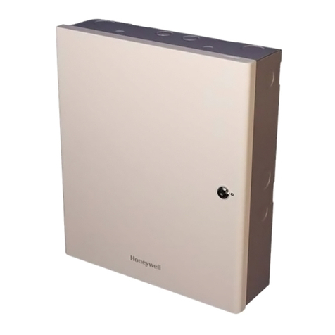
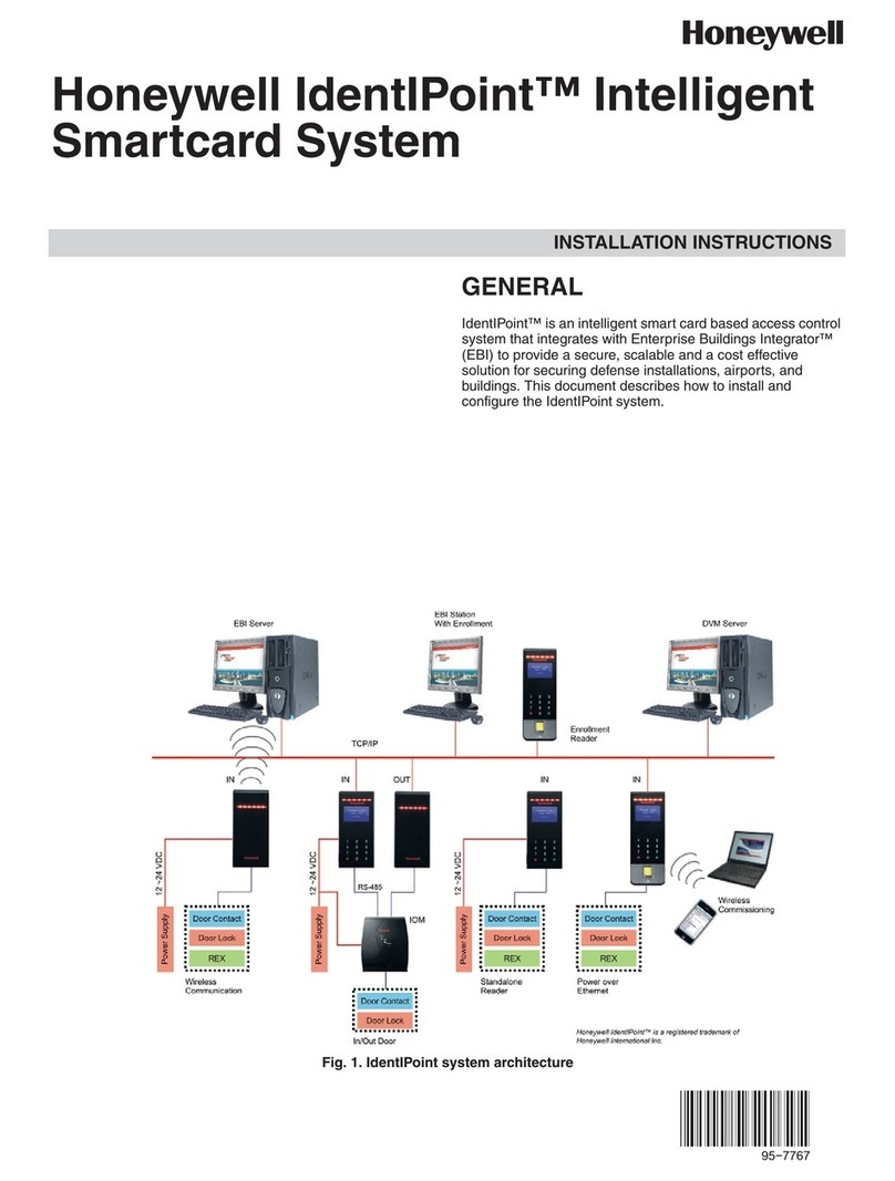
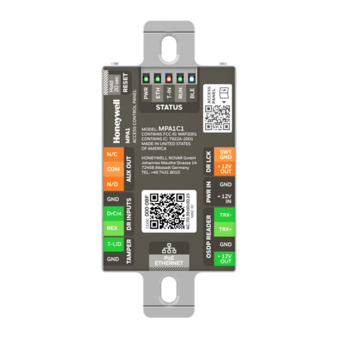
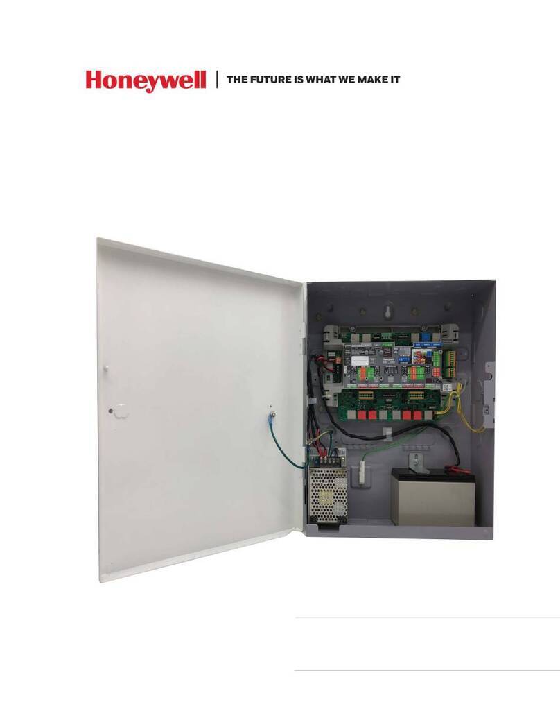
Honeywell MPA1C1 User manual

MPA1C1
Access Control Unit
Installation Guide
For MPA1C1 Controller and MPA1ENCP Plastic Enclosure
Document 800-26169
09/2020 Rev E

1
Copyright © 2020 Honeywell. All rights reserved.
All product and brand names are the service marks, trademarks, regis-
tered trademarks, or registered service marks of their respective owners.
Printed in the United States of America. Honeywell reserves the right to
change any information in this document at any time without prior
notice.
Ordering Information
Please contact your local Honeywell representative or visit us on the web
at www.honeywellaccess.com for information about ordering.
Feedback
Honeywell appreciates your comments about this manual. Please visit
us on the web at www.honeywellaccess.com to post your comments.
Digital Manuals and manuals in other languages
Honeywell provides this manual in English and other languages Online:
Get Online Document Here
The link is also found by scanning the following QR code.

2
Installing the MPA1C1 Panels
•Introduction beginning on page 3
•Panel Components and Descriptions beginning on page 5
•Download and Install App beginning on page 13
•Mounting and Installing Options beginning on page 14
•MPA1ENCP Plastic Enclosure Installation beginning on page
15
•Commission the MPA1C1 beginning on page 33
•Hardware Specifications beginning on page 39
•Maintenance beginning on page 44
•Troubleshooting beginning on page 45
•Technical Support beginning on page 49

3
Introduction
This document describes how to install the MPA1C1 access
control unit.

4
Access Control Overview
An access control system protects and preserves an enterprise’s
resources by providing authentication, authorization, and
administration services.
Authentication is a process that verifies a user’s identity. If the
user is verified, the system then either grants or denies access to
specific areas and resources.
Administration includes the creation and modification of user
accounts and access privileges.
An access control system consists of hardware and software,
usually configured in a network environment over a standard
network protocol.
Access control units, readers, door strikes, and video and other
devices, for example, are configured to control and monitor
access to a company site.

5
MPA1C1 Overview
An MPA1C1 access control unit is a full-featured single-door
web-based smart edge access control system.
The MPA1C1 panel includes a built-in web server, built-in Ether-
net, and PoE (Power over Ethernet) capability. You can manage
the access control system using either a web browser, MPC
(MAXPRO® Cloud) or WIN-PAK.
For supported configurations, see beginning on page 32 to view
illustrations of the supported MPA1C1 system configurations.
Note:
• The MPA1C1 web server/browser is intended for monitoring and
programming use only.
• MPC and WIN-PAK software are intended for monitoring and
programming use only, and have not been evaluated by UL.
Panel Components and Descriptions
Note: This device complies with part 15 of the FCC Rules. Operation is
subject to the following two conditions: (1) This device may not
cause harmful interference, and (2) this device must accept any
interference received, including interference that may cause
undesired operation.
The MPA1C1 panel consists of a web browser enabled control-
ler, and a PoE power supply. The following figures show the
MPA1C1 panel wiring and components and the typical door
configurations that the panel can be used in.
6
MPA1C1 Compact Enclosure wiring connections
Note:
• Install according to ANSI/NFPA70 National Electrical Code and local
codes.
• All wiring except for the CAT5 Cable shall be shielded wire.
• Terminal blocks are rated for 12-26 AWG wiring.
• UL Listed and suitably rated ferrule connectors have to be used in
case of braid copper wires or in case of two wires connected to one
screw terminal. The cross section of the ferrule connectors and the
wire gauges have to match.
• To fix the ferrule connectors please use a proper crimping tool.
• Canadian Electrical Code, part 1. Local Authority Having Jurisdiction.

7
MPA1C1 door with single-reader and door strike
MPA1C1 door with two-readers and door strike

8
MPA1C1 Access Control Unit
You can use the MPA1C1 panel as a standalone panel with inde-
pendent card and transaction storage or, with a host software
upgrade, as a fully monitored online access control device.
The three panel inputs are capable of four state supervision:
Normal, Alarm, Short and Cut. One input is used for door status
on each door. There is one tamper input in the MPA1C1.
All three inputs can also be used as additional inputs when not
required for their default purpose. By default non-supervised
inputs are used for Request to Exit (REX) button, Door Position
Switch (DrCnt), and Tamper (T-LID).
Note: The MPA1C1 can only connect to OSDP readers.
For MPA1C1 reader specifications, see Hardware Specifications
beginning on page 39.

9
Real-Time Clock Protection
The Panel’s Real Time Clock (RTC) is backed up using a CR1220
3V Lithium/Mangane Dioxide coin cell battery which will power
the real- time clock for the least 100 days in the absence of pri-
mary power.
Ensure the battery coin cell has been placed in the battery
holder when MPA1C1 is commissioned and when in normal
operation.
Replace the battery only with CR1220 Coin Cell type. Using
another type of battery may result in a risk of Fire Or Explosion.
Refer the Owner's Manual for Safety Instructions.
Caution: Risk of Fire, Explosion, And Burns. Do Not
Recharge, Disassemble, Heat Above 100°C, or
Incinerate.

10
Power Supply
The MPA1C1 can be powered from PoE or an external 12VDC
power supply.
Power over Ethernet
The MPA1C1 controller can be powered by Power over Ethernet (PoE -
802.3af). This PoE can supply a total system current of 1070mA
@12VDC.
However the MPA1C1 controller can consume 300mA of current. This
leaves 700mA of total current for the 12VDC external power to eg read-
ers and locks.
See Hardware Specifications beginning on page 39, for further details
on current limits using PoE.
Use of PoE and compliance with safety regulations:
• PoE can be connected if the Ethernet cable is installed only inside the
building.
• If the connected Ethernet cable is (partly) installed outside the
building, then the MPA1C1 must be powered by an external
12VDC Power supply.
The system has not been evaluated by UL when
powered by Power over Ethernet.

11
External Power Supply
The MPA1C1 can also be powered from an external 12VDC
power supply.
If an external power supply is connected and powering, the
MPA1C1 will take power from the external power supply.
An external power supply is recommended in case of controlling
heavy duty locks (such as Magnetic locks), where output current
for the lock would exceed 500mA.
Backup power
The MPA1C1 can be powered from PoE or an external power supply. The
backup power supply must be connected to the power source.
Recommended backup power source
• For ULC60839-11-1 and UL294 and CAN/ULC60839-11-1
Complaint systems, DC Power shall be provided through a UL/ULC
listed access control, or burglar alarm power supply with class 2
limited output.
The 7Ah lead-acid battery in the external power supply is not
evaluated by UL294 and CAN/ULC60839-11-1
The battery or UPS provides standby backup power, depending
upon system configuration and activity.
For MPA1C1 power consumption details, see Power
consumptions beginning on page 41
Power Source Power Backup
PoE Switch or PoE inserter UPS (Unbreakable Power Supply)
External 12V Power 7Ah sealed lead-acid battery

12
Reset button
MPA1C1 has a reset button. While MPA1C1 is powered up and
RUN LED is blinking, press the reset button for 20 seconds to
reset to factory default configurations and activate the Blue-
tooth communication for the commissioning application.

13
Download and Install App
The panel needs the Device Utility App (Bluetooth Mobile App)
to complete commissioning.
Download the application from the App Store or Play Store.
Scan this QR code for the application in the App Store.
Get Device Utility App Here
Scan this QR code for the application in the Play Store.
Get Device Utility App Here
Minimal required Mobile Operating System:
• iPhone: iOS 13 or higher
• Android: Android 6 or higher

14
Mounting and Installing Options
The MPA1C1 controller (MPA1C1) has been designed to fit in a
single gang US electrical gang box.
To mount the MPA1C1:
• Fully wire the MPA1C1. Ensure all the cables have proper
strain relief, and use the provided zip tie for additional CAT5
Cable strain relief.
• Push the MPA1C1 into the junction box with LEDs visible.
MPA1C1 in a single gang US electrical gang box
• Place the light blocking label on the back of the single gang cover
plate.
• Attach any provided cover plate.
For compliance with UL294 and CAN/ULC60839-
11-1, the MPA1C1 is intended to be installed within
the secure/protected area.

15
MPA1ENCP Plastic Enclosure Installation
If the US gang box is not available or used, a plastic enclosure
with tamper is available as MPA1ENCP.
The MPA1C1 Controller slides and snaps into the enclosure
inner base without using any tools.
Make sure that the RJ45 Connector is on the outer left side.
The below figures show how to insert the MPA1C1 controller in
the MPA1ENCP inner base.

16
Note: The MPA1C1 Controller has been installed already in the
MPA1ENCP enclosure.

17
Wiring the enclosure tamper switch
The Lid tamper switch wires connect with the T-Lid inputs as
demonstrated below.
Note: There is an additional internal accelerometer tamper
switch that will detect any movement from the wall or from
a gang box

18
Fix Wirings
The design of the base is so that the wiring can be lead neatly in
the cabinet using the openings at the edges of the inner base.
The cables can be tied down the using the cable ties at the cable
tie points.

19
Break out tabs in the cover
Cables can be lead in the side of the cover when breaking out
the break out tabs per picture below.
This manual suits for next models
1
Table of contents
Other Honeywell IP Access Controllers manuals

Honeywell
Honeywell NetAXS-123 Troubleshooting guide

Honeywell
Honeywell temaline TK C12 User manual

Honeywell
Honeywell MPA1 User manual

Honeywell
Honeywell IDENT-KEY 3 Instruction manual

Honeywell
Honeywell NetAXS-123 User manual

Honeywell
Honeywell MPA2C3 User manual

Honeywell
Honeywell MPA2 Troubleshooting guide

Honeywell
Honeywell IdentIPoint User manual

Honeywell
Honeywell OmniAssure Touch Mullion User manual

Honeywell
Honeywell VISTA CA-FP-100F User manual