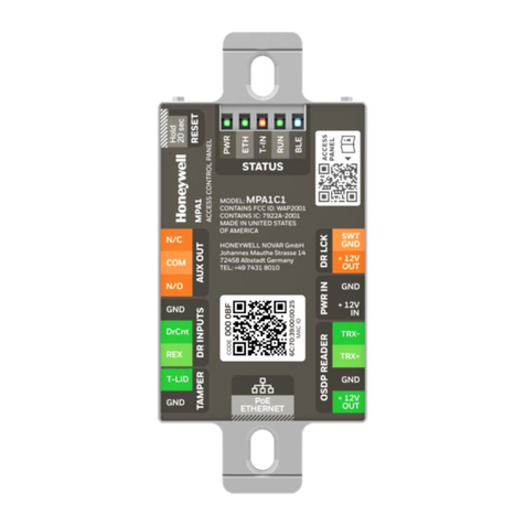
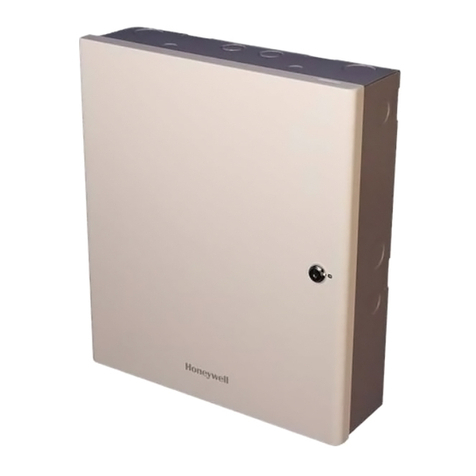
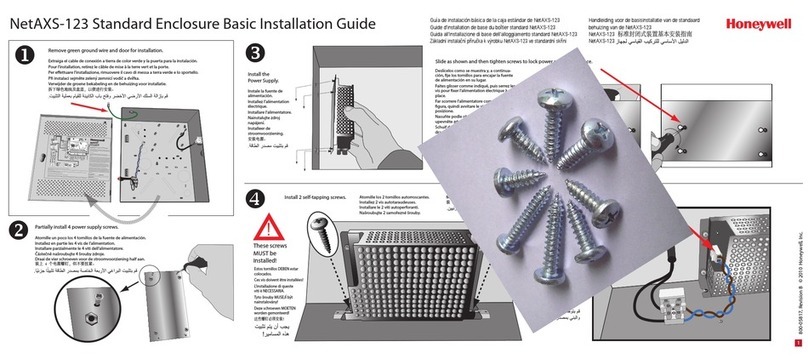
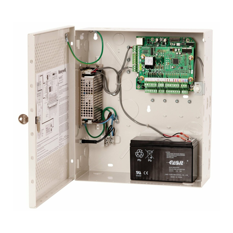
Honeywell MPA2C3 User manual

Installation Manual
MPA2C3
Access Control Unit

2 MPA2C3 Installation Guide

MPA2C3 Installation Guide 3
TABLE OF CONTENTS
Chapter 1 - Introduction............................................................................... 11
Introduction................................................................................................................................... 11
Packing List............................................................................................................................. 11
Access Control Unit Overview.......................................................................................... 16
Compliance Note .................................................................................................................. 17
Chapter 2 - Access Control Panel Overview............................................. 21
Access Control Panel Wiring and Components........................................................ 22
LEDs and Button................................................................................................................... 24
Power Supply.......................................................................................................................... 26
Supervised and Non-Supervised Input Wiring ............................................................... 27
MPA2C3 Access Control Unit .......................................................................................... 29
Real-time Clock Protection............................................................................................... 30
Chapter 3 - Wiring the Panel and Devices................................................. 27
Shutting down and Restart the Panel .......................................................................... 27
System Wiring Overview..................................................................................................... 28
Wiring the Door Peripherals ............................................................................................. 37
MPA2C3 2-door system reader configurations....................................................... 44
Wiegand mode panel setting.................................................................................................. 45
OSDP mode panel setting................................................................................................. 46
Wiring Readers....................................................................................................................... 48
Power limitations for the reader connections ........................................................... 49
External reader power......................................................................................................... 49
Wiegand Reader Wiring...................................................................................................... 52

4 MPA2C3 installation Guide
OSDP Bus termination........................................................................................................55
OSDP EOL Termination in 2 - Door Panel...................................................................56
OSDP EOL termination in 4-door panels ....................................................................58
OSDP ADDRESSING VIA PANEL .....................................................................................59
OSDP READER ADDRESS ASSIGNMENT FEATURE VIA PANEL .......................60
OSDP reader controls..........................................................................................................60
OSDP READER ADDRESS ASSIGNMENT FEATURE VIA PANEL .......................61
Address assignment procedure for OSDP readers ..................................................61
Correcting/Editing Reader Address ..............................................................................63
Option 1: Connect reader with highest address first. .............................................66
Option 2: reset all reader and reassign all one by one ...........................................67
Wiring Input/Output Devices of Doors ..............................................................................71
Red RJ45 Door terminals ...................................................................................................87
DIP Switch Settings........................................................................................................... 101
Jumper Settings.................................................................................................................. 104
Communications................................................................................................................ 107
Configuring FACP input functionality ....................................................................... 112
FACP input functionality ................................................................................................. 112
Door Access Modes ........................................................................................................... 113
Door access mode indication ........................................................................................ 114
FACP input prerequisites ................................................................................................ 117
FACP input set up procedure – FAIL-SAFE INSTALLATION ............................. 118
Connect the Fire Panel’s output wiring to the FACP input................................ 121
FACP input activation in Alarm – Notifications..................................................... 124
Chapter 4 - Mounting the Enclosure........................................................125
Metal Enclosure Installation................................................................................................ 125
Wiring the AC Power Cord............................................................................................... 126
Mounting the Enclosure ........................................................................................................ 129
Chapter 5 - System Configuration............................................................135
System Configuration....................................................................................................... 135
Ethernet – Network Dedicated to Access Control ................................................. 136
USB Connection ................................................................................................................. 137

MPA2C3 Installation Manual 5
RS-485 Loop Connection via MPA2C3......................................................................138
Ethernet Virtual Loop with All Panels on Common IP Subnet .........................139
Ethernet Virtual Loop – Network Dedicated to Access Control .......................140
Ethernet Connection with Ethernet Virtual Loop – Multiple Locations.......141
Chapter 6 - Hardware Specifications .......................................................143
Feature list MPA2C3 2-door panel..............................................................................143
Feature list MPA2C3 4-door panel..............................................................................147
Maximum Output Loading of Power Supply ...........................................................150
PoE+ Power Limitations...................................................................................................151
Battery Supply......................................................................................................................153
Cables......................................................................................................................................154
Enclosure Label and Symbols EU:EMC/CE...................................................................165
Panel Settings ............................................................................................................................167
Chapter 7 - Firmware Specification..........................................................167
Panel Settings.......................................................................................................................167
Firmware Upgrades ...........................................................................................................168
4-door License.....................................................................................................................168
Basic Standalone Operation.................................................................................................168
Door Egress (REX) / Door Lock / Door Status Operation...................................168
Chapter 8 - Maintenance............................................................................169
Chapter 9 - Troubleshooting......................................................................171
Chapter 10 - Appendix ................................................................................173
Main setting configuration under UL testing................................................................175
Primary input........................................................................................................................175
Secondary Input..................................................................................................................175
Powered Output ..................................................................................................................175
Dry contact Output ............................................................................................................176

6 MPA2C3 installation Guide

MPA2C3 Installation Guide 5
Copyright © 2022 Honeywell. All rights reserved.
All product and brand names are the service marks, trademarks, registered trade-
marks, or registered service marks of their respective owners. Honeywell reserves
the right to change any information in this document at any time without prior
notice.
Ordering Information
Please contact your local Honeywell representative or visit us on the web at https://
www.security.honeywell.de or information about ordering.
Feedback
Honeywell appreciates your comments about this manual. Please visit us on the
web athttps://www.security.honeywell.de to post your comments.
Digital Manuals and manuals in other languages
Honeywell provides this manual in English and other languages Online:
Get Online Document Here
The link is also found by scanning the following QR code.

6 MPA2C3 Installation Guide

MPA2C3 Installation Guide 7
WARNING Installation and servicing should be performed only by qualified and
experienced technicians to conform to all local codes and to maintain your war-
ranty.
Regulatory Statements
Waste Electrical and Electronic Equipment (WEEE)
Correct Disposal of this Product (applicable in the European Union and other
European countries with separate collection systems).
This product should be disposed of, at the end of its useful life, as per applicable
local laws, regulations, and procedures.
INSTALLATION
Install in accordance with the manufacturer’s instructions.
Installation and servicing should be performed only by qualified and experienced
technicians to conform to all local codes and to maintain your warranty.
POWER SOURCES - This product should be operated only from the type of power
source indicated in the guide. If you are not sure of the type of power supplied to
your facility, consult your product dealer or local power company.
MOUNTING SYSTEM - Use only with a mounting system recommended by the
manufacturer, or sold with the product.
ATTACHMENTS/ACCESSORIES - Do not use attachments/accessories not recom-
mended by the product manufacturer as they may result in the risk of fire, electric
shock, or injury to persons.
SERVICING - Do not attempt to service this unit yourself. Refer all servicing to
qualified service personnel.
REPLACEMENT PARTS - When replacement parts are required, be sure the service
technician has used replacement parts specified by the manufacturer or have the
same characteristics as the original part. Unauthorized substitutions may result in
fire, electric shock or other hazards. Using replacement parts or accessories other
than the original manufacturers may invalidate the warranty.

8 MPA2C3 Installation Guide
Warranty and Service
Subject to the terms and conditions listed on the product warranty, during the war-
ranty period Honeywell will repair or replace, at its sole option, free of charge, any
defective products returned prepaid.
Be sure to have the model number, serial number, and the nature of the problem
available for the technical service representative.
Prior authorization must be obtained for all returns, exchanges, or credits. Items
shipped to Honeywell without a clearly identified Return Merchandise Authoriza-
tion (RMA) number may be refused.
Safety Notes
Read the instructions carefully and thoroughly before installing the device and
putting it into operation.
They contain important information on installation, reprogramming and operation.
The device is a state-of-the-art product. Only use the device:
• In accordance with regulations,
• When it is has been installed and is functioning correctly,
• In accordance with technical data
The manufacturer is not responsible for damage that is caused by use not in accor-
dance with regulations.
Installation and programming as well as maintenance and repair work may only be
carried out by skilled, authorized personnel.
De-energize the entire system before soldering and connecting.
Carry out soldering work with a temperature-controlled electrically isolated solder-
ing iron.
To avoid a short circuit with battery, Use isolated tools for installation and service.
Do not use the device in a potentially explosive environment or in rooms where
metal or plastic decomposing vapours are emitted.
ATTENTION! Important security notes to dangerous voltage operation
•(Voltages >= 42,4 V peak value or >= 60 V DC, e.g. also 230 V AC).
•Work on primary voltage should only be carried out by skilled, authorized personnel.
• Only connect units as per IEC EN 62368-1 to the module.
• Appropriate overload protection must be provided in the mains circuit.
For installation an appropriate mains separator is required.
• Switch off the primary circuit before carrying out installation or maintenance
work.
• Only cables with double insulation may be used. e.g. NYM, NYM, H05VV, H05RR
or similar cables.
MPA2C3 Installation Guide 9
• Up to a current of 6A, a cable cross-section of at least 0.75 mm² must be used,
up to 10A a cable cross-section of at least 1.00 mm².
• Do not lengthen or connect the activating line in the housing without double
insulation.
• Do not store loose, unused connecting cables in the housing.
• Route the incoming cable separately through the provided recess to the
terminal.
• Minimum distances must be observed: Clearance: 4 mm, creepage distance: 5
mm.
• Strip the ends of the cores (approx. 4 mm).
• Use core end sleeves to clamp leads.
• Fix the incoming cable with the provided cable binder to the housing.
• Observe the VDE safety regulations and provisions of the local electricity
supplier.
Caution: Risk of explosion if battery is replaced by an incorrect type. Dispose of used batteries
according to caution on the battery and all local and national regulations.
Caution: Replace the DC battery if it shows any sign of corrosion or leakage or if the battery is 2
years old or older. Replacing battery must be done by skilled person.
Safety Symbol
The following symblos are used in this manual:
Read carefully more details, regarding charging and discharging of battery.
Shock Risk-Isolate before attempting access.
Protective Earth
Caution- Instruction, or Information with vital importance for the safety of person-
nel, or equipment.

10 MPA2C3 Installation Guide

CHAPTER
1
MPA2C3 Installation Guide 11
INTRODUCTION
Introduction
This document describes how to install the MPA2C3 access control unit, how to
wire the access control panel to doors, readers, downstream devices, how to con-
figure the system for different connection loops and so forth.
Note: All figures shown in this manual are for illustration purpose only. Actual products may
vary due to product enhancement.
Packing List
The MPA2C3 access control unit includes compact plastic enclosures and stan-
dard metal enclosures. The compact plastic enclosure supports the access control
panel (MPA2C3-4), and the standard metal enclosure supports the access control
panel MPA2C3) or the 4-door licensed access control panel MPA2C3). There are
multiple SKU configurations for the unit. For more information, refer to the tables
below.

12 MPA2C3 Installation Guide
Table 1-1 MPA2MPSE/MPA4MPSE Packing List
Metal Housing
(MPA2ENCME)
Enclosure
Power Supply
Battery Cable
Battery Terminal
Cable Clamp
Enclosure
x1
Battery Terminal
(for Battery)
x2

MPA2C3 Installation Guide 13
Access Control Panel
(MPA2C3 )
(MPA2C3-4)
Access Control
Panel
M5 Screw
#6 Screw
#6 Anchor
Resistor
(2K2 Ohm)
Quick Start
Guide
(800-26607-02)
Enclosure Label
Additional Accessory Convertor
Door Connection
Cable
#6 Screw
x4
2*MPA2MPSE
4*MPA4MPSE
2*MPA2MPSE
4*MPA4MPSE

14 MPA2C3 Installation Guide
Table 1-2 MPA2MPSU/MPA4MPSU Packing List
Metal Housing
MPA2ENCMU
Enclosure
Battery Cable
Battery Terminal
Cable Clamp
Access Control
Panel
(MPA2C3)
(MPA2C3-4)
Access Control
Panel
M5 Screw
#6 Screw
#6 Anchor
Resistor
(2K2 Ohm)
Quick Start
Guide
(800-26607-02)

MPA2C3 Installation Guide 15
Additional
Accessory
Battery
(MPA2BAT7)
Power Cable
(MPA2S5)
Convertor
2*MPA2MPSU
4*MPA4MPSU
2*MPA2MPSE
4*MPA4MPSE

16 MPA2C3 Installation Guide
Access Control Unit Overview
An MPA2C3 access control unit is a full-featured 2-door web-based access control
system. The panel has all needed inputs/outputs and readers/door connections to
be used as a 4-door panel (MPA2C3-4). The 4-door panel is enabled by a license.
The MPA2C3 panel includes a built-in web service by built-in Ethernet and USB
support, and PoE+ (Power over Ethernet) capability. You can manage the access
control system by using the built-in web services, MAXPRO® Cloud or WIN-PAK®
XE/SE/PE/CS. For supported configurations, see Chapter 5 to view illustrations of
the supported MPA2C3 system configurations.
Two types of enclosures, compact plastic enclosures and metal standard enclo-
sures, are designed for the access control unit. A maximum of 2 doors are sup-
ported by the compact plastic enclosure. A maximum of 2 doors or up to 4 doors
are supported by the standard metal enclosure. For the 3-door or 4-door system, a
license is required.
Note: The MPA2C3 built-in web services are intended for monitoring and programming use
only.
Note: MAXPRO® Cloud and WIN-PAK® XE/SE/PE/CS software is intended for monitoring
and programming use only and have not been evaluated by UL.
Note: To use MPA2C3 as a 4-door access control system, a license needs to be activated.
Once the license file is applied on the panel, the user can use the 4-door controller
(MPA2C3-4). Please contact Honeywell customer support in your region for 4-door
support.

MPA2C3 Installation Guide 17
Standard Metal Enclosure
The standard metal housing includes a metal enclosure and serveral accessories.
For the detailed information, see Packing List on page 11. This unit can be powered
by the power supply with a backup battery, or by PoE+.
Figure 1-1 MPA2ENCME/MPA2ENCMU Access Control Overview
Note: For MPA2MPSE and MPA4MPSE the 12 VDC Battery must be purchased separately.
Compliance Note
This device complies with Part 15 of the FCC Rules / Innovation, Science and Eco-
nomic Development Canada’s licence-exempt RSS standard(s). Operation is sub-
ject to the following two conditions: (1) this device may not cause harmful
interference, and (2) this device must accept any interference received, including
interference that may cause undesired operation.
L’émetteur/récepteur exempt de licence contenu dans le présent appareil est con-
forme aux CNR d’Innovation, Sciences et Développement économique Canada
applicables aux appareils radio exempts de licence. L’exploitation est autorisée aux
deux conditions suivantes :
(1) L’appareil ne doit pas produire de brouillage;
(2) L’appareil doit accepter tout brouillage radioélectrique subi, même si le brouil-
lage est susceptible d’en compromettre le fonctionnement.
Changes or modifications not expressly approved by the party responsible for
compliance could void the user's authority to operate the equipment.
Multiple Tie-down Points
Simple Panel Door Removal
for Easy Wall Mounting
and Cabling
Simple Panel Door Removal
for Easy Wall Mounting
and Cabling
10-19 VDC / 50 W
Primary Power Supply
12 VDC Backup Battery
Panel Door Grounding Point
Enclosure Lid Tamper
Off Wall Tamper
All-in Smart Control Panel
(MPA2C3/MP2C3-4)
Multiple Knock-out HolesMultiple Knock-out Holes
Multiple Knock-out Holes
Main Socket USA/ UL Version only
Space for

18 MPA2C3 Installation Guide
This equipment has been tested and found to comply with the limits for
a Class B digital device, pursuant to part 15 of the FCC Rules. These
limits are designed to provide reasonable protection against harmful
interference in a residential installation. This equipment generates
uses and can radiate radio frequency energy and, if not installed and
used in accordance with the instructions, may cause harmful interference
to radio communications. However, there is no guarantee that interference
will not occur in a particular installation. If this equipment does cause
harmful interference to radio or television reception, which can be
determined by turning the equipment off and on, the user is encouraged
to try to correct the interference by one or more of the followingmeasures:
—Reorient or relocate the receiving antenna.
—Increase the separation between the equipment and receiver.
—Connect the equipment into an outlet on a circuit different from that to which the
receiver is connected.
—Consult the dealer or an experienced radio/TV technician for help.
To satisfy FCC / ISED RF exposure requirements, a separation distance of 20 cm or
more should be maintained between the antenna of this device and persons during
device operation. To ensure compliance, operations at closer than this distance is
not recommended.
Les antennes installées doivent être situées de facon à ce que la population ne
puisse y être exposée à une distance de moin de 20 cm. Installer les antennes de
facon à ce
que le personnel ne puisse approcher à 20 cm ou moins de la position centrale de l’
antenne.La FCC des éltats-unis stipule que cet appareil doit être en tout temps
éloigné d’au moins 20 cm des personnes pendant son functionnement.
To obtain applicable EU Compliance Declaration of Conformities for this product,
please refer to our website http://www.security.honeywell.com/hsce/interna-
tional/index.html.
For any additional information regarding the compliance of this product to any
EU-specific requirements, please contact:
Honeywell Novar GmbH
Johannes Mauthe Strasse 14
72458 Albstadt
Phone 00497431801-0
This manual suits for next models
1
Table of contents
Other Honeywell IP Access Controllers manuals

Honeywell
Honeywell NetAXS-123 User manual

Honeywell
Honeywell Tema-Voyager Compact User manual

Honeywell
Honeywell NetAXS-123 User manual

Honeywell
Honeywell NetAXS-123 Troubleshooting guide

Honeywell
Honeywell MPA1 User manual

Honeywell
Honeywell temaline TK C12 User manual

Honeywell
Honeywell IdentIPoint User manual

Honeywell
Honeywell MPA2 User manual

Honeywell
Honeywell MPA2 Troubleshooting guide

Honeywell
Honeywell MPA1C1 User manual