manuals.online logo
Brands
  1. Home
  2. •
  3. Brands
  4. •
  5. Honeywell
  6. •
  7. Security System
  8. •
  9. Honeywell ADEMCO 745 3 Series Assembly instructions

Honeywell ADEMCO 745 3 Series Assembly instructions

N9080-1V2 3/04
ADEMCO 745x3
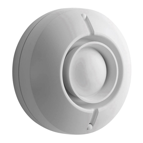
Voice Siren Driver
INSTALLATION AND SETUP GUIDE
FEATURES
• Listed for: UL 985 Household Fire, UL 1023 Household
Burglary, UL 609 Commercial Burglary.
• Generates voice output in English, Spanish, and French.
• Separate messages for FIRE and BURGLARY conditions.
• Separate siren sounds for FIRE and BURGLARY
conditions.
• Terminal strip for secure connection to control panel.
• Selectable input level (High/Low) for FIRE/BURGLARY
inputs.
• Supervision feature for speaker and speaker wiring.
• Compatible with control panels within parameters
stated.
• Sounder options for bell ringback/bell test.
• Compatible with 8 - 32 ohm speakers.
• Operates on 12 - 16V DC.
• Small compact size for easy installation using double-
sided tape provided – measures only 4” x 2-5/8” x 1-1/4”.
OUTPUT SELECTION
The voice driver can be programmed for the desired alarm
output on burglary and fire by means of jumpers JP1
through JP4, as indicated in Table 1. See Figure 1 for
location of jumpers.
Table 1. Output Selection
JUMPERS OUTPUT
JP1 JP2 JP3 JP4 FIRE BURG
– – – – ENG ENG
X – – – ENG/FREN ENG/FREN
– X – – ENG/SPAN ENG/SPAN
X X – –
ENG/SPAN/FREN
ENG/SPAN/FREN
– – X – FREN FREN
X – X – SPAN SPAN
– X X – SIREN SIREN
X X X – ENG SIREN
– – – X ENG/FREN SIREN
– – X X ENG/SPAN SIREN
– X – X
ENG/SPAN/FREN
SIREN
– X X X SIREN ENG
X – X X SIREN FREN
X X – X SIREN SPAN
X – – X SIREN ENG/SPAN/FREN
X X X X ENG ENG
X = CUT, – = INTACT
Bell Test/Ringback Options (JP5)
If jumper JP5 is kept intact, the siren driver will generate a
steady sound for bell test and bell ringback conditions.
If the jumper is cut, a warbled sound will be generated for
bell test/ringback conditions.
NOTE: If this mode is selected, a fire signal will
momentarily generate a warbled siren sound for the initial
portion of the siren sound and then revert to the normal
siren sound and voice message. Jumper JP5 shall be cut in
UL Listed systems.
Burglary Signal Polarity (JP6)
Intact = High (12V+), cut = Low (0V)
The burglary message may be activated by either a steady
logic high or steady logic low, as provided by the control
panel (refer to the control panel’s instructions).
When jumper JP6 is intact, activation is by a logic high
(12V+) at terminal 2. Cut jumper JP6 for activation by a
logic low (0V).
Note that a pulsing high or low (pulse width 0.25 to 1.75
seconds, that is provided by some panels) connected to the
Burglary/Fire input (terminal 2) will be interpreted as a
Fire condition and will produce the fire message.
Fire Signal Polarity (JP7)
Intact = High (12V+), cut = Low (0V).
As in the case of Burglary signal polarity, the fire message
may be activated by either a logic high or logic low, but at
terminal 3. When jumper JP7 is intact, activation is by a
logic high (12V+). Cut jumper JP7 for activation by a logic
low (0V).
Burglary Messages:
ENGLISH:
YOU HAVE VIOLATED THE PROTECTED AREA…THE
POLICE HAVE BEEN CALLED…LEAVE IMMEDIATELY!
SPANISH:
USTED HA VIOLADO UNA AREA PROTEGIDA…LA
POLICIA HA SIDO LLAMADA SALGA INMEDIATAMENTE!
FRENCH:
VOUS AVEZ PENETRE UN LIEU SURVEILLE…LA POLICE
A ETE AVERTI…EVAQUEZ IMMEDIATEMENT!
Burglary Alarm Sequence:
Warble Siren sound, Burglary Voice Message (repeated 3
times), 15-second Warble Siren Sound.
Sequence will repeat until the Burglary output condition is
terminated.
Fire Messages:
ENGLISH: FIRE…LEAVE IMMEDIATELY!
SPANISH: FUEGO…SALGA INMEDIATAMENTE!
FRENCH: AU FEU!…EVAQUEZ IMMEDIATEMENT!
Fire Alarm Sequence:
Steady Siren Sound, Fire Voice Message repeated 3 times
on a single language output, followed by 15 seconds of
Steady Siren Sound. Sequence will repeat until the Fire
output condition is terminated.
WIRING CONNECTIONS
Wiring connections to the terminals are as follows: Refer to
Figure 1 (and Table 2 for Honeywell products).
1 SUPV: SPEAKER/WIRING SUPERVISION (OPTIONAL).
For supervision of speaker and associated wiring, connect to
the high (+) side of a 24-hour zone that is activated by a
short. Removing the speaker or shorting either speaker
terminal to ground where operation is affected will appear
as a short on the zone. Note that in series-connected
¬19Ul
N9080-1V2 3/04
multiple speaker systems, cutting any speaker will trip the
control panel’s supervision zone. In parallel-connected
speaker systems, each branch must be cut before the control
panel’s supervision zone will trip. Note: The Supervision
option has been determined to be compatible with the
controls listed in Table 2.
2 B/F: BURGLARY/FIRE INPUT:
Connect the control panel’s Burglary (steady) Output to this
terminal. This terminal may also be used to trip the FIRE
message if the control provides a pulsing output for fire (re-
programming may be required). In this case, no connection
to terminal 3 is required.
3F: FIRE INPUT:
Connect the control panel’s output designation as the FIRE
(steady) Output to this terminal (unless this output was
connected to terminal 2).
4 SPKR & 5 SPKR: SPEAKER TERMINALS:
Connect an 8-ohm, 16-ohm, or 32-ohm 15-watt speaker to
these terminals. See Figure 3 for multiple speaker
configurations. For UL installations, the Listed Ademco
705-820, 713, or 746-32 speakers must be used.
6(+): 12VDC(+) POWER INPUT:
Connect to a 12VDC (+) source on the control.
7(-): GND(-) GROUND INPUT:
Connect to a ground point (-) on the control panel.
Speakers Specifications: Use compatible speakers above.
Sound Output: 85 dB minimum @10 ft.
Current Drain (max):
8-ohm Speaker: 1400 mA (steady siren)
12-ohm Speaker: 1050 mA (steady siren)
16-ohm Speaker: 875 mA (steady siren)
32-ohm Speaker: 500 mA (steady siren)
Important: The 745x3 must be mounted in the control
cabinet.
745x3-001-V0
SPEAKER
8
SEE
TABLE
1
JP2
JP3
JP6
JP7
JP4
JP5
JP1
BURG & FIRE
INPUT SIGNAL
INTACT = HIGH
CUT = LOW
FIRE
BURG
SPEAKER SUPERVISION
CONNECT TO (+) SIDE OF
24 - HR ZONE ON CONTROL.*
TO BURGLARY/FIRE ALARM
OUTPUT ON CONTROL.**
TO FIRE ALARM
OUTPUT ON CONTROL
*IF EOLR SUPERVISION DESIRED ON THIS ZONE,
USE APPROPRIATE EOLR IN ACCORDANCE WITH
THE CONTROL'S INSTRUCTIONS.
**IF THE ALARM OUTPUT IS
STEADY
FOR BURG AND
PULSING
FOR FIRE, NO CONNECTION IS NEEDED AT TERMINAL 3.
4365721
12VDC
GND
VOICE
SIREN
DRIVER
Figure 1. Siren Driver Board
745x3-002-V0
VOICE
SIREN
DRIVER
7( )
6( )
CONTROL
GROUND
12V ( )
POS
( )
NEG
( )
2 AMP
IN-LINE FUSE
BATT
Figure 2. Connecting Power from the System’s Battery
(Not applicable for UL installations)
745x3-003-V0
2 SPEAKERS
16 OHM
LOAD
4 SPEAKERS
8 OHM LOAD
3 SPEAKERS
12 OHM
LOAD
8
8
8
8
8
8
8
8
8
5
4
5
4
5
4
Figure 3. Typical Multiple Speaker Configurations
Table 2. Wiring Connections For Honeywell Ademco
Control Panels*
REFER TO THE INSTALLATION INSTRUCTIONS FOR THE
CONTROL PANEL THAT IS USED WITH THIS DEVICE FOR
WARRANTY INFORMATION AND LIMITATIONS OF THE
ENTIRE ALARM SYSTEM.
165 Eileen Way, Syosset, New York 11791
Copyright © 2004 Honeywell International, Inc.
www.honeywell.com/security
745x3 TERMINALS
ADEMCO
CONTROL
PANEL 1 2 3 4 5 6 7
4110
4110XM
VISTA-10P/15P/20P
VISTA-10SE/20SE
3 –
Splice to Red BATT
lead thru 2A fuse
(see Fig. 2).
For UL
Installations, use
the 32-ohm speaker
(746-32) and
connect to +12V
LUG
4
4140XM 8 – +12V LUG 15
4140XMP
4140XMPT
VISTA-40/
VISTA-50P
VISTA-128B/BP
OPTIONAL SPKR SUPERVISION
(CONNECT TO 24-HR ZONE)
4 –
SPEAKER CONNECTIONS
Splice to RED
BATT lead thru 2A
fuse
(see Fig. 2).
For UL
Installations, use
the 32-ohm speaker
(746-32) and
connect to +12V
LUG.
5
* For further information, consult the control panel’s instructions.
Note: If using the 745x3 with a control with a built-in siren
driver, consult that control’s instructions to determine the method
to disable the built-in siren driver and enable the bell output.

Other Honeywell Security System manuals

Honeywell VISTA-15P User manual

Honeywell

Honeywell VISTA-15P User manual

Honeywell OMNI-408 User manual

Honeywell

Honeywell OMNI-408 User manual

Honeywell Domonial User manual

Honeywell

Honeywell Domonial User manual

Honeywell LYNX Touch L7000 Series User manual

Honeywell

Honeywell LYNX Touch L7000 Series User manual

Honeywell HS321S User manual

Honeywell

Honeywell HS321S User manual

Honeywell Accenta Series Quick start guide

Honeywell

Honeywell Accenta Series Quick start guide

Honeywell Ademco Vista-48LA Operating instructions

Honeywell

Honeywell Ademco Vista-48LA Operating instructions

Honeywell FBII OMNI 600 User manual

Honeywell

Honeywell FBII OMNI 600 User manual

Honeywell 3516 User manual

Honeywell

Honeywell 3516 User manual

Honeywell X-618 Quick start guide

Honeywell

Honeywell X-618 Quick start guide

Honeywell L5200 Series Operating instructions

Honeywell

Honeywell L5200 Series Operating instructions

Honeywell Lynx Plus Series Assembly instructions

Honeywell

Honeywell Lynx Plus Series Assembly instructions

Honeywell Galaxy Flex V3 Series User guide

Honeywell

Honeywell Galaxy Flex V3 Series User guide

Honeywell First Alert FA168CPS User manual

Honeywell

Honeywell First Alert FA168CPS User manual

Honeywell GENT Nano panel-based Training manual

Honeywell

Honeywell GENT Nano panel-based Training manual

Honeywell VISTA-128FBPT User manual

Honeywell

Honeywell VISTA-128FBPT User manual

Honeywell 6272CV User manual

Honeywell

Honeywell 6272CV User manual

Honeywell VISTA 15P - Ademco 6 Zone Control Panel User manual

Honeywell

Honeywell VISTA 15P - Ademco 6 Zone Control Panel User manual

Honeywell 032211.17 User manual

Honeywell

Honeywell 032211.17 User manual

Honeywell Galaxy 3-48C Owner's manual

Honeywell

Honeywell Galaxy 3-48C Owner's manual

Honeywell ADEMCO VISTA-20PSIA User manual

Honeywell

Honeywell ADEMCO VISTA-20PSIA User manual

Honeywell Galaxy Dimension User manual

Honeywell

Honeywell Galaxy Dimension User manual

Honeywell Le Sucre User manual

Honeywell

Honeywell Le Sucre User manual

Honeywell VISTA-128BPEN Assembly instructions

Honeywell

Honeywell VISTA-128BPEN Assembly instructions

Popular Security System manuals by other brands

Esse-ti HELPY 2W-L300 quick guide

Esse-ti

Esse-ti HELPY 2W-L300 quick guide

Altronix OA2 Series installation guide

Altronix

Altronix OA2 Series installation guide

Target DCMA-4000-ANZ instruction manual

Target

Target DCMA-4000-ANZ instruction manual

CIK Home Security user guide

CIK

CIK Home Security user guide

IRIS Touch 4 NG Series Quick Installation & Maintenance Guide

IRIS

IRIS Touch 4 NG Series Quick Installation & Maintenance Guide

BT UC-351GP/E-UK Installation, maintenance and operation manual

BT

BT UC-351GP/E-UK Installation, maintenance and operation manual

Johnson SVD205 Instructions for use

Johnson

Johnson SVD205 Instructions for use

Night Owl C50XFR Series Quick setup guide

Night Owl

Night Owl C50XFR Series Quick setup guide

Radio Shack 49-421A owner's manual

Radio Shack

Radio Shack 49-421A owner's manual

MedicalAlert In-Home Landline user guide

MedicalAlert

MedicalAlert In-Home Landline user guide

Inter-m PE-603 Operation manual

Inter-m

Inter-m PE-603 Operation manual

OnQ Technologies 925 owner's manual

OnQ Technologies

OnQ Technologies 925 owner's manual

Bellman & Symfon Visit 868 BE1410 manual

Bellman & Symfon

Bellman & Symfon Visit 868 BE1410 manual

Mercury 350.149UK user manual

Mercury

Mercury 350.149UK user manual

Extel WESV 87101 Installation and operation manual

Extel

Extel WESV 87101 Installation and operation manual

GST GST200N manual

GST

GST GST200N manual

Chuango WS-105 user manual

Chuango

Chuango WS-105 user manual

ITI SX-IVB owner's manual

ITI

ITI SX-IVB owner's manual

manuals.online logo
manuals.online logoBrands
  • About & Mission
  • Contact us
  • Privacy Policy
  • Terms and Conditions

Copyright 2025 Manuals.Online. All Rights Reserved.