10
Operation
Stick one of IC tags provided on the grip top and such of the
soldering iron. Stick on a plastic surface and such since IC tags
stuck on metallic surfaces may not function normally.
Sticking an IC tag
A new IC tag has no ID number.
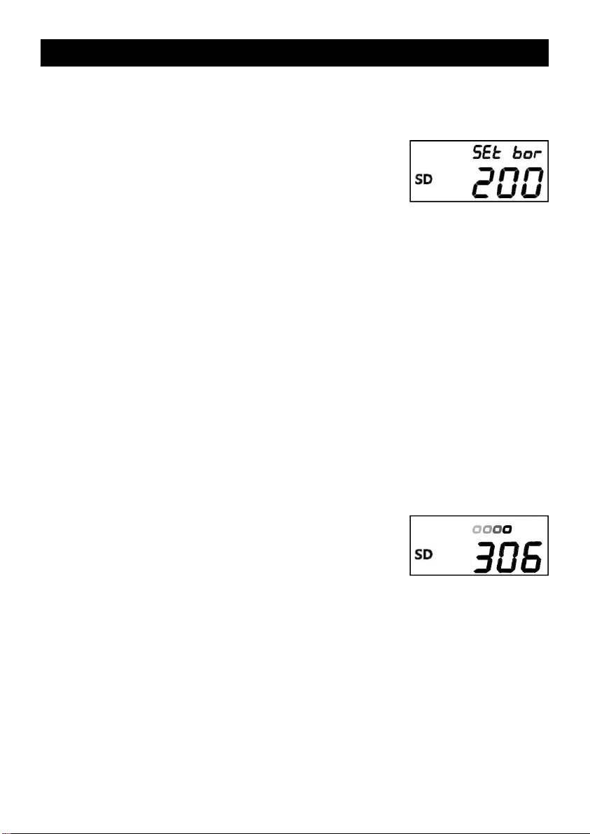
When bring close the IC tag to the
antenna part of H-769, the
recorded contents are displayed
buzzing “Pi!”
Be careful not to burn by the
soldering iron.
An H-769 can administer 99 soldering irons correspond to ID
numbers 01 to 99.
On and after the 100th soldering irons can not recorded. Those
are displayed by under bars.
*Always hold IC tags up over the antenna one by one. Holding
plural IC tags up at a time could cause confusion and
malfunction.
*5 IC tags are provided with H-769. purchase H-769-1 IC tag (5/
pack) depending on increase of soldering irons to be
administered.
*See page 17 for procedures confirming recorded IDs of
soldering irons or deleting them.
The soldering irons/IC tags recorded by other H-769 already
can not be recorded. Those data are simply displayed.
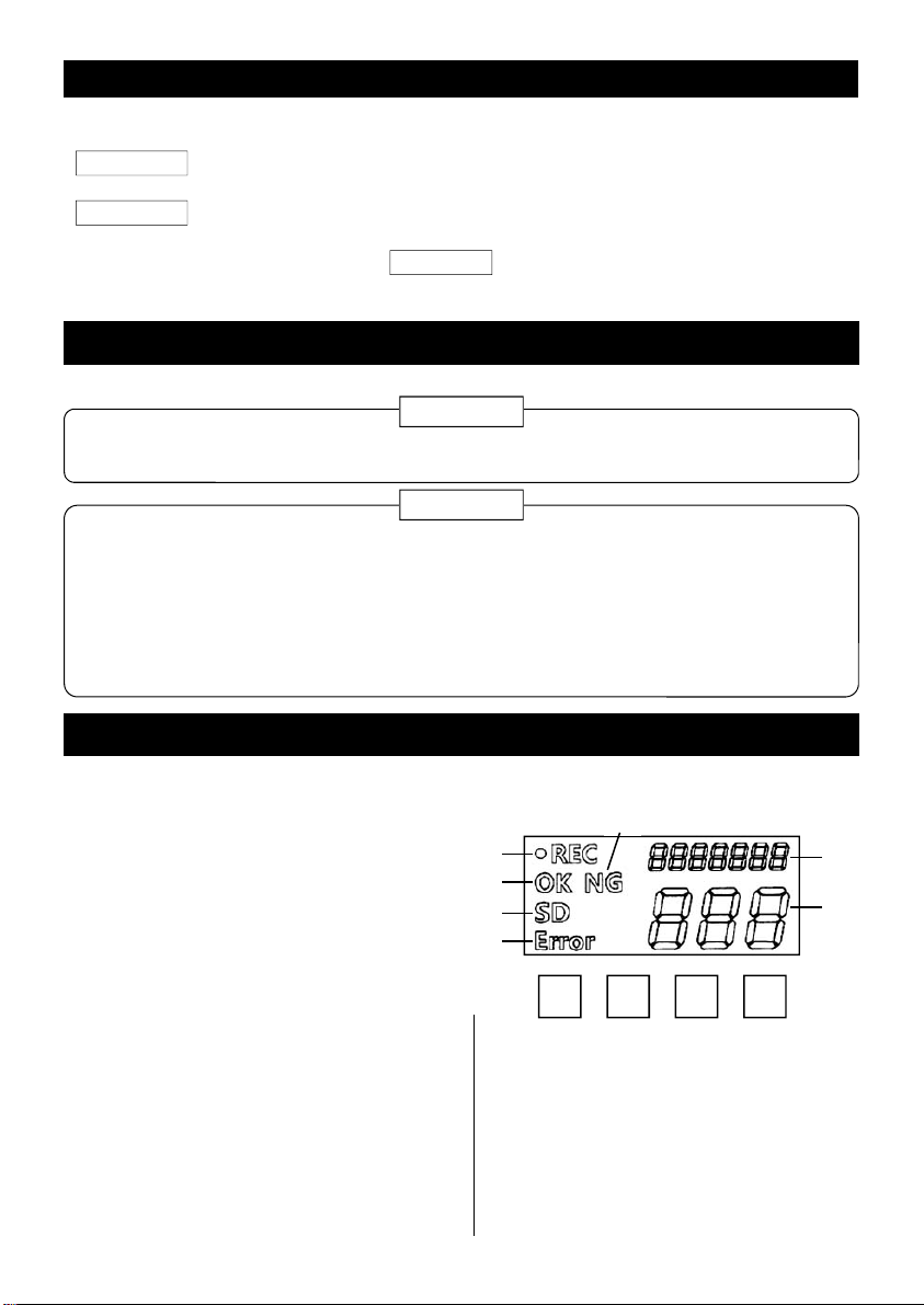
Serial number of this H-769
(seven-digit number)
ID number of soldering iron
(01 to 99)
Soldering iron discrimination function
(Preparation)
This is the function to distinguish plural soldering irons.
The ID number given to each soldering iron and measured data of which are saved in the
SD card being combined.
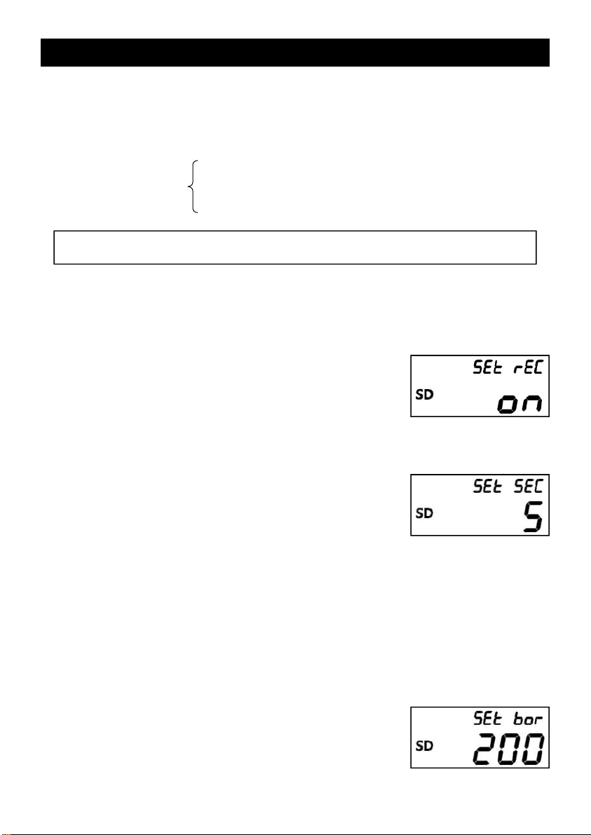
Inserting SD card When insert a SD card into the SD card slot, “SD” is displayed
on the LCD buzzing “Pi!”
*The bar will spin at the upper right corner of the LCD during
the SD card is accessing the CPU. Do not shut the power or
remove the SD card till this dynamic image goes out. This
could damage the data in the SD card.
*The soldering iron discrimination function does not work
without inserting SD cards.
Adding ID number